Table of Contents
Advertisement
Quick Links
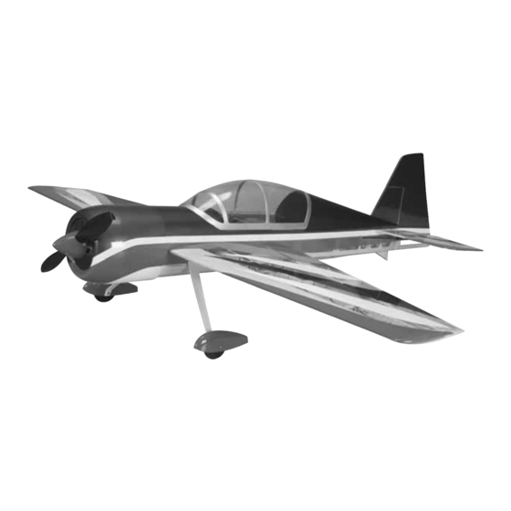
Wingspan: 41 in [1040mm]
Wing Area: 356 sq in [23dm
2
Weight: 24 – 27 oz [680 – 765g]
Wing Loading: 9.7 – 10.9 oz/sq ft [30 – 33g/dm
Length: 38 in [960mm]
Requires (not included):
Radio: 4-channel with four micro servos, two 6" [152mm] servo
extensions and one Y-harness
Motor: RimFire
™
35-30-950 out-runner (GPMG4590) or
Ammo
24-33-4040 in-runner brushless motor (GPMG5165)
™
Gear-Drive: 24mm gear-drive with 4.5:1 gear ratio
ESC: 25 amp brushless ESC
Battery: 3-cell 1250 to 2100mAh LiPo battery &
LiPo-compatible charger
Great Planes
®
Model Manufacturing Co. guarantees this kit to be free from defects in both material and workmanship at the date of
purchase. This warranty does not cover any component parts damaged by use or modification. In no case shall Great Planes' liability
exceed the original cost of the purchased kit. Further, Great Planes reserves the right to change or modify this warranty without notice.
In that Great Planes has no control over the final assembly or material used for final assembly, no liability shall be assumed nor
accepted for any damage resulting from the use by the user of the final user-assembled product. By the act of using the user-assembled
product, the user accepts all resulting liability.
If the buyer is not prepared to accept the liability associated with the use of this product, the buyer is advised to return this
kit immediately in new and unused condition to the place of purchase.
To make a warranty claim send the defective part or item to Hobby Services at the address below:
Include a letter stating your name, return shipping address, as much contact information as possible (daytime telephone number, fax
number, e-mail address), a detailed description of the problem and a photocopy of the purchase receipt. Upon receipt of the package
the problem will be evaluated as quickly as possible.
READ THROUGH THIS MANUAL BEFORE STARTING
CONSTRUCTION. IT CONTAINS IMPORTANT INSTRUCTIONS
AND WARNINGS CONCERNING THE ASSEMBLY AND
USE OF THIS MODEL.
Entire Contents © Copyright 2006
INSTRUCTION MANUAL
]
2
]
WARRANTY
Hobby Services
3002 N. Apollo Dr., Suite 1
Champaign, IL 61822 USA
™
Champaign, Illinois
(217) 398-8970, Ext 5
airsupport@greatplanes.com
GPMZ1542 for GPMA1542 V1.0
Advertisement
Table of Contents

Related Manuals for GREAT PLANES Yak 54 36 ARF


Summary of Contents for GREAT PLANES Yak 54 36 ARF
-
Page 1: Instruction Manual
Further, Great Planes reserves the right to change or modify this warranty without notice. In that Great Planes has no control over the final assembly or material used for final assembly, no liability shall be assumed nor accepted for any damage resulting from the use by the user of the final user-assembled product. -
Page 2: Table Of Contents
For the latest technical updates or manual corrections to the TABLE OF CONTENTS YAK 54 EP 3D ARF visit the Great Planes web site at www.greatplanes.com. Open the “Airplanes” link, then select the YAK 54 EP 3D ARF. If there is new technical INTRODUCTION..............2... -
Page 3: Decisions You Must Make
YAK 54 EP 3D ARF. However, the included firewall pieces how you build it; therefore, we cannot in any way are designed to work specifically with the Great Planes guarantee the performance of your completed model, and motors listed. -
Page 4: Required Adhesive & Building Supplies
(GPMP0617) instructions will make a recommendation. Note: Do not use Great Planes LiPo 1500mAh 11.1V 3S 8C Whenever just epoxy is specified you may use either • Discharge (GPMP0831). This battery pack is not capable of 30-minute (or 45-minute) epoxy or 6-minute epoxy. -
Page 5: Common Abbreviations
Description How to Purchase METRIC CONVERSIONS Missing pieces Contact Product Support Instruction manual Contact Product Support Full-size plans Not available Kit parts listed below Hobby Supplier 1" = 25.4mm (conversion factor) 1/64" .4mm 3/4" 19.0mm Replacement Parts List 1/32" .8mm 1"... -
Page 6: Kit Inspection
If any parts are missing or are not of acceptable quality, or if you need assistance with assembly, contact Product Support. When reporting defective or missing parts, use the part names exactly as they are written in the Kit Contents list. Great Planes Product Support 3002 N. Apollo Drive, Suite 1 Champaign, IL 61822 Telephone: (217) 398-8970, ext. -
Page 7: Preparations
PREPARATIONS ❏ 1. If you have not done so already, remove the major parts of the kit from the box and inspect for damage. If any parts are damaged or missing, contact Product Support at the address or telephone number listed in the “Kit Inspection”... - Page 8 ❏ 4. Attach a 6" [150mm] servo extension to each aileron servo and wrap the connection with heat-shrink tubing or transparent tape. ❏ 7. Locate two double-sided servo arms that fit the output splines of your aileron servos and four adjustable clevises. ❏...
-
Page 9: Install The Wing Panels
❏ 12. Use the position of the control horn to adjust the length of the pushrods as needed. Remove the servo arms from the aileron servos. Connect the other adjustable clevises on the aileron pushrods to the control horns and reattach the servo arms. -
Page 10: Assemble The Tail Section
ASSEMBLE THE TAIL SECTION ❏ 3. Thoroughly coat the root ribs of the wing panels and the wing pockets in the fuselage with 30-minute epoxy and slide them into place. Do not put epoxy on the interlocking spars at this time. Being sure that the wing panels are fully ❏... - Page 11 ❏ ❏ 3. The elevator halves should be positioned behind the 7. Carefully cut a slot for the elevator control horn on the horizontal stabilizer so that there is a 1/16" [1.6mm] gap underside of the left elevator half. The slot should be 1/2" between the ends of the stab and elevators.
- Page 12 with the vertical fin and remove the covering inside your marks. Reposition the stab into the fuse and stand back several feet behind the model and view it from the rear. Confirm that the stabilizer is parallel with the wing panels. If not, use tape or a weight to straighten it.
-
Page 13: Install The Tail Servos & Pushrods
INSTALL THE TAIL SERVOS & PUSHRODS ❏ 4. As you did with the ailerons, test fit the double-sided servo arms perpendicular to the servo cases. If the servo arm does not fit onto the servo spline perpendicular to the servo case, remove it from the servo and rotate it 180°. Decide which way fits best (closest to perpendicular) and cut off the arm that isn’t used. -
Page 14: Install The Landing Gear
in the servo arm using thin CA. (Do not glue the clevis to the servo arm!). Confirm that your servo arm is still perpendicular to the servo case. Install a 2mm x 4mm sheet metal screw into the clevis on the elevator control horn and carefully tighten it down. -
Page 15: Mount The Motor
Great Planes brushless C35-30-950 out-runner motor and the brushless B24-33-4040 in-runner equipped with the Great Planes 24mm gear drive. Other motors may be able to be installed; however, modification to one of the mounting box firewalls would be necessary to suit the size and mount pattern of your equipment. -
Page 16: Out-Runner Brushless Motor
longer side piece being on the left of the box). The front Out-runner Brushless Motor piece is installed in the aft slots. ❏ 2. Attach the aluminum adapter to the back of the out- runner using the screws supplied with the motor. Attach the motor to the mounting box with four 3mm x 6mm machine screws, four 3mm washers, and thread-locking compound. - Page 17 antenna in place. For a cleaner look, we ran the receiver antenna through the inside of the fuselage to the back. The antenna exits from a small hole drilled in the location shown. ❏ 2. Connect the servo leads to the receiver. If you are using a 4-channel receiver, you will also need a dual servo extension or Y-harness for the aileron servos.
- Page 18 ❏ 9. Trim the covering between the spars at the back of the battery hatch for cool air exits. ❏ 7. Install two 2.4mm x 8mm flat head self-tapping screws into the pre-drilled holes in the battery hatch blocks. Glue two magnets into the battery hatch with medium CA as shown.
-
Page 19: Final Assembly
you did with the cowl ring, apply a light skin coating of thin FINAL ASSEMBLY CA over the magnets after they have been glued into the fuselage. Let the CA cure without accelerator. ❏ 1. Prepare the inside of the cowl by lightly scuffing it with 220- grit sandpaper. -
Page 20: Apply The Decals
3. Position decal on the model where desired. Holding the decal down, use a paper towel to wipe most of the water away. Use a Great Planes AccuThrow (or a ruler) to accurately measure and set the control throw of each control surface as 4. -
Page 21: Balance The Model (C.g.)
Flying your model at these throws will provide you the battery pack installed, place the model upside-down on with the greatest chance for successful first flights. If, after a Great Planes CG Machine ™ , or lift it at the balance point you have become accustomed to the way the Yak 54 EP you marked . -
Page 22: Preflight
We use a Top Flite Precision Magnetic Prop Balancer ™ • ONLY charge through the “charge” lead. NEVER charge (TOPQ5700) in the workshop and keep a Great Planes through the “discharge” lead. Fingertip Prop Balancer (GPMQ5000) in our flight box. •... -
Page 23: Ama Safety Code (Excerpts)
• ALWAYS set charger’s output volts to match battery volts. the aircraft are allowed at or in the front of the flight line. • ALWAYS charge in a fireproof location. Intentional flying behind the flight line is prohibited. • NEVER trickle charge. •... -
Page 24: Flying
to weight ratio will allow the plane to accelerate to flying speed FLYING almost instantly. Climb to a comfortable altitude and throttle back to a lower power setting. The Yak 54 EP ARF is a great-flying model that flies Flight smoothly and predictably. -
Page 25: 3D Flying
make certain you are on the desired rates (high/low rates). right rudder) during this maneuver. Some planes will require A flight plan greatly reduces the chances of crashing your a little aileron correction to keep the wings level as well. model just because of poor planning and impulsive moves. - Page 26 The rudder is now used to turn the model. This maneuver will Vertical Hover take some practice as there are a lot of small corrections made to keep most planes in the maneuver. This is one maneuver where less control is needed. Too much elevator and the model goes into an uncontrollable stall.
- Page 27 Have a ball! But always stay in control and fly in a safe manner. GOOD LUCK AND GREAT FLYING! Make a copy of this identification tag and put it on or inside your model.
- Page 28 BUILDING NOTES Kit Purchased Date: _______________________ Date Construction Finished: _________________ Where Purchased:_________________________ Finished Weight: __________________________ Date Construction Started: __________________ Date of First Flight: ________________________ FLIGHT LOG...
Need help?
Do you have a question about the Yak 54 36 ARF and is the answer not in the manual?
Questions and answers