Table of Contents
Advertisement
Quick Links
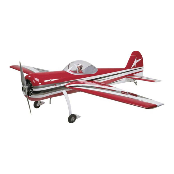
SPECIFICATIONS
Wingspan: 88 in [2235mm]
Wing Area: 1473 in
Wing Loading: 28−31 oz/ft
WARRANTY
Great Planes
®
Model Manufacturing Co. guarantees this kit to
be free from defects in both material and workmanship at the
date of purchase. This warranty does not cover any component
parts damaged by use or modification. In no case shall Great
Planes' liability exceed the original cost of the purchased kit.
Further, Great Planes reserves the right to change or modify this
warranty without notice.
In that Great Planes has no control over the final assembly or
material used for final assembly, no liability shall be assumed nor
accepted for any damage resulting from the use by the user of
the final user-assembled product. By the act of using the
user-assembled product, the user accepts all resulting liability.
If the buyer is not prepared to accept the liability associated
with the use of this product, the buyer is advised to return
READ THROUGH THIS MANUAL BEFORE STARTING CONSTRUCTION. IT CONTAINS IMPORTANT
INSTRUCTIONS AND WARNINGS CONCERNING THE ASSEMBLY AND USE OF THIS MODEL.
Entire Contents © 2010
Length: 82.5 in [2095mm]
2
2
[95 dm
]
Weight: 18−19.5 lb [8160−8840 g]
2
2
[85−95 g /dm
]
Radio: 5 channel minimum / 9 channel or greater preferred
INSTRUCTION
MANUAL
this kit immediately in new and unused condition to the
place of purchase.
To make a warranty claim send the defective part or item to
Hobby Services at the address below:
Hobby Services
3002 N. Apollo Dr. Suite 1
Champaign IL 61822 USA
Include a letter stating your name, return shipping address, as
much contact information as possible (daytime telephone
number, fax number, e-mail address), a detailed description of
the problem and a photocopy of the purchase receipt. Upon
receipt of the package the problem will be evaluated as quickly
as possible.
airsupport@greatplanes.com
Engine: 50-55cu in [3.0 – 3.4cc]
two-stroke gasoline engine
Champaign, Illinois
(217) 398-8970, Ext 5
GPMA1230 Mnl
Advertisement
Table of Contents

Related Manuals for GREAT PLANES Yak-55M Performance Series


Summary of Contents for GREAT PLANES Yak-55M Performance Series
- Page 1 3002 N. Apollo Dr. Suite 1 Champaign IL 61822 USA In that Great Planes has no control over the final assembly or material used for final assembly, no liability shall be assumed nor Include a letter stating your name, return shipping address, as...
-
Page 2: Table Of Contents
fl ying near full-scale aircraft and avoid fl ying near or over For the latest technical updates or manual corrections to the groups of people. Yak-55M visit the Great Planes web site at www.greatplanes. com. Open the “Airplanes” link, then select the Yak-55M ARF. International Miniature Aircraft Assoc. -
Page 3: Safety Precautions
SAFETY PRECAUTIONS DECISIONS YOU MUST MAKE Protect Your Model, Yourself & Others … This is a partial list of items required to fi nish the Yak-55M that Follow These Important Safety Precautions may require planning or decision making before starting to build. -
Page 4: Muffl Er Recommendations
Muffler Recommendations Optional Supplies & Tools This airplane has been designed to accommodate a wide Here is a list of optional tools mentioned in the manual that variety of muffl er confi gurations. The stock muffl er and Pitts will help you build the Yak-55M. style muffl... -
Page 5: Kit Inspection
A roll of MonoKote includes full instructions Kit Contents list. for application. Following are the colors used on this model and order numbers for six foot rolls. Great Planes Product Support 3002 N Apollo Drive, Suite 1 Ph: (217) 398-8970, ext. 5 Champaign, IL 61822... -
Page 6: Ordering Replacement Parts
List that follows. The fastest, most economical service can be provided by your hobby dealer or mail-order company. To locate a hobby dealer, visit the Great Planes web site at www.greatplanes.com. Select “Where to Buy” in the menu across the top of the page and follow the instructions provided to locate a U.S., Canadian or International dealer. - Page 7 ❏ ❏ 4. The aileron servo will require a 1" [25mm] servo arm to get the required aileron throw. We recommend that a high strength metal servo arm be used. For our model we used the aluminum Futaba arm (FUTM2120). Open up the outermost hole in the servo arm by drilling a 1/8"...
- Page 8 How to Solder 1. Use denatured alcohol or other solvent to thoroughly clean the pushrod. Roughen the end of the pushrod with coarse sandpaper where it is to be soldered. 2. Apply a few drops of soldering fl ux to the end of the pushrod, then use a soldering iron or a torch to heat it.
-
Page 9: Assemble The Fuselage
❏ 1. Slide the landing gear into the fuselage on both the left and right side of the fuselage. The straight side of the landing gear should be towards the front of the fuselage. ❏ ❏ 10. Glue a 5/16" x 1" [7.9mm x 25mm] wood dowel into the two outermost holes in the wing root. - Page 10 ❏ ❏ 2. To achieve proper elevator control you will need to use a 1-1/2" heavy duty servo arm. We used the Futaba aluminum arm (FUTM2118). Enlarge the hole that is 1-1/4" [32mm] from the center of the servo spline with a 1/8"...
- Page 11 CORRECT INCORRECT Hinge Line Hinge Line ❏ ❏ ❏ 9. Using the pushrod wire as a guide, locate the plywood 12. Locate the two carbon fi ber stab tubes. Slide the shorter plate in the elevator servo. Position the large nylon black control length tube into the forward most hole in the rear of the fuselage horn on the plate, in line with the pushrod wire.
-
Page 12: Install The Rudder
Install the Rudder Install the Rudder Servos ❏ We have designed this airplane with the option to use one servo 1. Without using any with 250 oz-in. of torque or to use two, lower strength servos glue, install four hinges in tandem. - Page 13 ❏ ❏ 3. Position the aluminum servo arm on top of the disk. Drill a 3/32" [2.4mm] hole through the aluminum arm and through the disk. Do this for all four holes. Secure the arm to the disk with four 2-56 x 1/2" [13mm] machine screws and ❏...
- Page 14 DOUBLE SERVO INSTALLATION ❏ ❏ 1. For the dual rudder servo arm installations you will need two of the aluminum servo arms included in the kit and two of the round servo disks included with your radio system. The round servo disk needs to be at least 1"...
-
Page 15: Complete The Rudder Control Installation
❏ ❏ 8. Use pliers to pull the cable from the fi rst loop to reduce the size of the second loop. Squeeze the swage with pliers ❏ and then cut off the excess wire. Do this for both wires. 2. - Page 16 you drilled. (13/64 [5.2mm] is required as a clearance hole for removing the engine. If not you will need to remove and then a 10-24 bolt. If you are mounting a different engine, be sure to reinstall the engine. check the size of the mounting bolts before drilling the holes). ❏...
-
Page 17: Install The Fuel Tank
1" [25mm] on one end of each of the tubes with 200 grit sandpaper. Insert the tubes into the hole you drilled in the fi rewall. Be sure to insert the smooth end of the tube fi rst so that the roughened end contacts the fi rewall. Apply glue to the roughened end of the tubes and then make the end of the tube fl... -
Page 18: Install The Muffler
end of all three tubes. Insert the tubes into the stopper with the metal plates, and then solder a barb onto the other end of the two short tubes. Bend the vent tube and connect the pickup and gas compatible fueling/defueling lines (not included) to the short tubes. -
Page 19: Pitts Style Muffl Er Installation
Pitts Style Muffler Installation Canister Muffler Installation ❏ 1. Remove the two covers from the bottom of the fuselage. These two covers allow you to customize the fuselage for your choice of muffl er, canister or tuned pipe. For a canister, glue the rear cover in place to the fuselage. - Page 20 ❏ 6. Test fi t the canister and holders into the opening in the fuselage. When you are satisfi ed everything fi ts well, remove the canister and remove the holders from the canister. ❏ 7. Insert the taller of the two holders into the fuselage. Glue it on the seam where the plywood meets balsa wood.
-
Page 21: Tuned Pipe Installation
Tuned Pipe Installation MOUNT THE COWLING AND DUMMY ENGINE ❏ 1. The kit includes six 5/8" x 5/8" x 3/4" [16mm x 16mm x 19mm] hardwood cowl mounting blocks. Depending on the muffl er you chose to mount, you may not choose to use all of the blocks. - Page 22 ❏ 3. Install the cowl onto the fuselage. The cowl should over lap the fi rewall approximately 1/8" [3.2mm]. Using the lines you drew on the blocks, measure forward 1" from the mark you made. Drill a 3/32" [2.4mm] hole through the cowl and the block.
-
Page 23: Install The Main & Tail Wheels
satisfi ed, permanently glue the dummy engine to the cowl. The dummy engine needs to be glued to the cowl with a mixture of 5-minute epoxy and micro balloons. The addition of the micro balloons will prevent the glue from running. ❏... -
Page 24: Complete The Radio Installation
❏ 1. Locate the three plywood parts shown. These will become the servo / battery tray. Glue two 1/4" x 1/4" x 5/8" [6mm x 6mm x 15mm] hardwood blocks to both of the plywood parts as shown. The blocks should be installed even with the corners of the part. -
Page 25: Install The Canopy, Pilot And Instrument Panel
part on top of them as shown. Drill a 1/16" [1.6mm] hole through INSTALL THE CANOPY, PILOT the holes in each corner of the top piece and into each of the AND INSTRUMENT PANEL blocks. Insert and then remove a #2 x 3/8" [9.5mm] screw into each of the holes. -
Page 26: Apply The Decals
❏ 4. Attach the canopy hatch to the top of the fuselage with four 4-40 x 3/4" [19mm] screws, #4 lock washers and #4 fl at washers. Test fi t the canopy to the top of the fuselage to determine the mounting position. ❏... -
Page 27: Get The Model Ready To Fly
GET THE MODEL READY TO FLY Proper Pushrod Hookup AVOIDING FLUTTER, MAXIMIZING Check the Control Directions SERVO OUTPUT TORQUE ❏ 1. Turn on the transmitter and receiver and center the trims. If necessary, remove the servo arms from the servos and CONTROL reposition them so they are centered. -
Page 28: Balance The Model (C.g.)
ACCEPTABLE PUSHROD HOOKUP Balance the Model (C.G.) More than any other factor, the C.G. (center of gravity/ balance point) can have the greatest effect on how a model fl ies and could determine whether or not your fi rst fl ight will be successful. -
Page 29: Balance The Model Laterally
We use a Top Flite ® Precision Magnetic Prop Balancer (TOPQ5700) in the workshop and keep a Great Planes ❏ 2. If one wing always drops when you lift the model, it means Fingertip Prop Balancer (GPMQ5000) in our fl ight box. -
Page 30: Ama Safety Code Excerpts
Make all engine adjustments from behind the rotating CHECK LIST propeller. The engine gets hot! Do not touch it during or right after During the last few moments of preparation your mind may operation. Make sure fuel lines are in good condition so be elsewhere anticipating the excitement of the fi... -
Page 31: Flying
❏ 19. Cycle your receiver battery pack (if necessary) and Make certain all pushrod linkages are secure and free make sure it is fully charged. of play. If it fl uttered once, under similar circumstances ❏ it will probably fl utter again unless the problem is fi xed. 20. -
Page 32: Flight
your glide path and airspeed. If you are going to overshoot, Flight smoothly advance the throttle (always ready on the right rudder to counteract torque) and climb out to make another attempt. For reassurance and to keep an eye on other traffi c, it is a When you’re ready to make your landing fl...
Need help?
Do you have a question about the Yak-55M Performance Series and is the answer not in the manual?
Questions and answers