Table of Contents
Advertisement
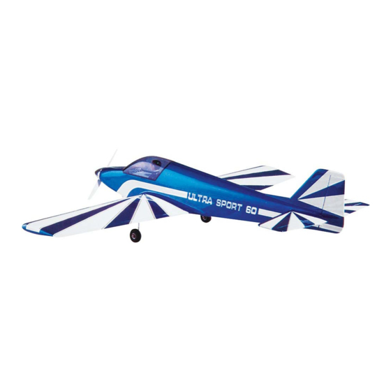
ULTRA SPORT 60
PLEASE READ THROUGH THIS INSTRUCTION BOOKLET IN ITS ENTIRETY BEFORE BEGINNING
ASSEMBLY. IT CONTAINS IMPORTANT INSTRUCTIONS AND WARNINGS CONCERNING THE ASSEMBLY
AND USE OF THIS MODEL.
WARNING! THIS IS NOT A TOY! THIS IS NOT A BEGINNER'S AIRPLANE!
This R/C kit and the model you will build is not a toy! It is capable of serious bodily harm and property
damage. IT IS YOUR RESPONSIBILITY AND YOURS ALONE to build this kit correctly, properly install
all R/C components and flying gear (engine, tank, pushrods, etc.) and to test the model and fly it only with
experienced, competent help, using common sense and in accordance with all safety standards as set down in the
Academy of Model Aeronautics Safety Code. It is suggested that you join the AMA to become properly insured
before you attempt to fly this model. IF YOU ARE JUST STARTING R/C MODELING. CONSULT YOUR
LOCAL HOBBY SHOP OR WRITE TO THE ACADEMY OF MODEL AERONAUTICS TO FIND AN
EXPERIENCED INSTRUCTOR IN YOUR AREA.
Academy of Model Aeronautics
5151 East Memorial Drive
Muncie, IN 47302-9252
(800)435-9262
INSTRUCTION BOOK
P.O. BOX 788
URBANA, ILLINOIS 61801
(217)398-8970
Advertisement
Table of Contents

Related Manuals for GREAT PLANES ULTRA SPORT 60


Summary of Contents for GREAT PLANES ULTRA SPORT 60
- Page 1 ULTRA SPORT 60 INSTRUCTION BOOK PLEASE READ THROUGH THIS INSTRUCTION BOOKLET IN ITS ENTIRETY BEFORE BEGINNING ASSEMBLY. IT CONTAINS IMPORTANT INSTRUCTIONS AND WARNINGS CONCERNING THE ASSEMBLY AND USE OF THIS MODEL. WARNING! THIS IS NOT A TOY! THIS IS NOT A BEGINNER'S AIRPLANE! This R/C kit and the model you will build is not a toy! It is capable of serious bodily harm and property damage.
-
Page 2: Table Of Contents
TABLE OF CONTENTS INTRODUCTION ... . . 3 Install Wing Fairings ... . . 30 Precautions ....3 Install Wing Fillets . -
Page 3: Introduction
INSTRUCTIONS IN BOXES LIKE THIS ARE istics of a good basic trainer such as the Great Planes PT VERY IMPORTANT AND SHOULD BE FOL- Series airplanes. On the other hand, if you have already... -
Page 4: Decisions You Must Make
DECISIONS YOU MUST MAKE NOW ENGINE AND MOUNT SELECTION NOTE: If you choose to power your Ultra Sport 60 with a 4. cycle engine, keep in mind that the RPM of your engine will be considerably less than that of a 2-cycle engine; therefore,... -
Page 5: Die Patterns
DIE DRAWINGS Use this drawing to help you identify the die-cut parts... -
Page 6: Types Of Wood
TYPES OF WOOD B A S S W O O O BALSA 3. Working on a flat surface covered with waxed paper, glue the fin front to the fin rear, then glue on the fin tip. Sand the front of the fin tip to blend with the fin, as shown on the GET READY TO BUILD plan. -
Page 7: Stabilizer And Elevator
7/64" hole in the rudder, and groove the rudder leading edge to accept the tailgear wire and the nylon tailgear bearing. 6. Sand both sides of the elevators to a taper as shown DO NOT GLUE YET! (The hole is drilled slightly oversize on the plans. -
Page 8: Install Hinges
NOTE: The following instructions explain how to build the wing on a flat surface, directly on the plans. An alternate method is to use a Great Planes Wing Jig (available from your local hobby dealer). Many expert modelers prefer to use a 1. -
Page 9: Build The Wing Panels
BUILD THE WING PANELS NOTE: If you will be installing a retractable landing gear, disregard Steps 6 and 7. NOTE: It will be helpful to build the wing on a piece of "Celotex" or other semi-soft (and flat) surface, into which 6. - Page 10 10. Place the ribs on the spar in their approximate CENTER L.E. VERTICALLY position, but do not glue. NOTE: Make sure ribs W-2, ON FRONT OF RIBS W-3 and W-4 are installed with the LG notches down, and W-l is installed with the servo opening pointing up. L.E.
- Page 11 23. Prepare the 3/32" balsa leading edge sheeting by sanding the front edge to a slight bevel so it will fit snugly against the back of the leading edge. 3/32" Balsa L.E. Sheeting Bevel this edge Using the 1/16" ply dihedral brace as a temporary spacer, glue the 3/32"...
- Page 12 NOTE: If you are installing retracts, disregard steps 26 through 29. Photo of finished wing with retract mechanism removed. NOTE: If you will be installing retracts, now is the time to glue in the 1/16" ply die-cut rib doublers to the front portion of ribs W-3 and W-4.
-
Page 13: Join Wing Panels
IMPORTANT: The shape of the leading edge will affect the way this airplane performs snap rolls and spins. A blunt, rounded leading edge will "soften" the stall, making the plane very docile when flying slowly, enabling it to flare nose-high for very slow landings;... -
Page 14: Sand "Flats" On Le And Te
File end to wedge shape pieces in place with epoxy. HINT: Use masking tape to hold these pieces to the wing TE, to aid in correct positioning. 2. Roughen the surface of the plastic bearing tubes SAND "FLATS" ON LE AND TE with 100-grit sandpaper. -
Page 15: Install Wing Tips
2. Trial fit the 4" wide fiberglass cloth in place. You 9. After the glue has set, trim the excess cloth at the can use a scissors or a paper punch to cut holes in the glass trailing edge with a sharp Xacto knife followed by a sanding cloth for the aileron torque rod horns. -
Page 16: Install Ailerons
4. Cut the right wing tip loose from the wing and use a Dremel Moto Tool to hollow out the wing tip. (This will help to compensate for the weight of the engine head and muffler). 5. Now securely glue the right wing tip in place. to make room for the torque rod bearings. -
Page 17: Install Wing Bolt Plate
Sand the wing bolt plate flush with the wing TE. FILL LANDING GEAR SLOTS 1. Temporarily install the main LG wires. 2. Check the plan for the location of the nylon landing gear straps and temporarily install them, using #2x3/8 sheet 2. -
Page 18: Fuselage Assembly
retract mechanism. Cut a clearance slot in rib W-3 for the LG FUSELAGE ASSEMBLY wire. Cut an opening in the bottom LE sheet and in rib W-2 for the wheel well. 3. lEnclose the wheel well by running vertical grain PREPARE FUSE SIDES 1/16"... -
Page 19: Assemble Lower Fuselage
6. Find the two die-cut 1/8" ply fuselage doublers and PLAN IT OUT! It is important that the fuse doubler and fuse the four die-cut 1/8" ply firewall spacers. Note that the side line up along the top edge and the front of the wing opening. - Page 20 the plan and hold it securely in place with pins, tape or weights (or you may spray it lightly with 3M "77" spray adhesive, to hold it firmly but temporarily down on the plan). 7. Trial fit (do not glue) the following parts together Fuse top, fuse sides, die-cut 1/8"...
-
Page 21: Drill Engine Mount
16. Cut pieces of 3/8" balsa triangle to fit around the aft edges of F-1, and glue them in place. DRILL ENGINE MOUNT (Great Planes MM60L mount) 1. Place the engine pointing straight ahead on the 14. Before installing the firewall (F-l), you may drill mount and mark the mounting hole locations on the mount. -
Page 22: Install Servos, Guide Tubes
Method 2: Cut threads into the holes you just drilled using a 6-32 tap and tap wrench. If you use this method you'll have to supply your own bolts (6-32 x 1" socket head cap screws) for attaching the engine to the mount. NOTE; 8-32 hardware is recommended if you are installing a 4-cycle engine. -
Page 23: Mount The Wing To The Fuse
3. Insert the die-cut 1/8" ply F-2A in place against the back of F-2 (do not glue). 4. Insert the 1/4" wing dowels into the wing so they stick out only 1/8". 5. With the fuselage upside down on a flat surface, trial fit the wing into the wing saddle. - Page 24 meter" or by measuring down to the flat surface from the center of the leading and trailing edges. The measurements should be the same (zero degrees incidence). CAUTION: If your flat surface is not level, you will get erroneous incidence readings! If you are working on a flat surface that is not level, you must set the wing incidence the same as your flat surface.
-
Page 25: Fit Fuel Tank, Fuelproofing
sand the entire fuse bottom, forward ofF-2A, in preparation 5. Now remove the engine mount and fuelproof the inside of the fuel tank compartment and the front of F-l by for installation of the chin block. brushing on a coat of polyester resin or 30-minute epoxy thinned with alcohol. - Page 26 correct angle. NOTE: The gauge is used only for setting the angle (do not glue the gauge in). 7. Glue the bottom edge of the sheeting to the top of the fuse sides. 2. Glue F-4A to the front of F-4. Glue F-5A to the front of F-5.
-
Page 27: Assemble Nose Section
NOTE: The turtle deck is designed to be as light as possible, HINT: For a super-smooth and uniform finish on your turtle deck, cut a 2-1/4" x 11" strip of 320 or 400-grit wet-or-dry while still providing sufficient durability for normal use. If your airplane will be handled by "ham-fisted"...
Need help?
Do you have a question about the ULTRA SPORT 60 and is the answer not in the manual?
Questions and answers