Table of Contents
Advertisement
Quick Links
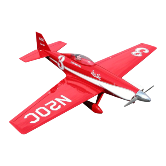
Wingspan: 63 in [1600mm]
Wing Area: 775 sq in [50 dm
Weight: 7.25 - 8.25 lb [3290 - 3740 g]
Wing Loading: 21.5 - 24.5 oz/sq ft [65 - 75 g/dm
Length: 56.5 in [1435mm]
Radio: 4-channel, 5 servos
Engine: .61cu in [10cc] two-stroke,
.91cu in [15cc] four-stroke
Great Planes
®
Model Manufacturing Co. guarantees this kit to
be free from defects in both material and workmanship at the date
of purchase. This warranty does not cover any component parts
damaged by use or modification. In no case shall Great Planes'
liability exceed the original cost of the purchased kit. Further,
Great Planes reserves the right to change or modify this warranty
without notice.
In that Great Planes has no control over the final assembly or
material used for final assembly, no liability shall be assumed nor
accepted for any damage resulting from the use by the user of the
final user-assembled product. By the act of using the user-
assembled product, the user accepts all resulting liability.
READ THIS MANUAL BEFORE STARTING
CONSTRUCTION. IT CONTAINS IMPORTANT
INSTRUCTIONS AND WARNINGS CONCERNING
THE ASSEMBLY AND USE OF THIS MODEL.
Entire Contents © Copyright 2004
INSTRUCTION MANUAL
2
]
2
]
WARRANTY
If the buyer is not prepared to accept the liability associated
with the use of this product, the buyer is advised to return
this kit immediately in new and unused condition to the place
of purchase.
To make a warranty claim, send
the defective part or item to
Hobby Services at this address.
Include a letter stating your name, return shipping address, as
much contact information as possible (daytime telephone number,
fax number, e-mail address), a detailed description of the problem
and a photocopy of the purchase receipt. Upon receipt of the
package the problem will be evaluated as quickly as possible.
Telephone: (217) 398-8970 ext. 5
airsupport@greatplanes.com
Hobby Services
3002 N. Apollo Dr. Suite 1
Champaign IL 61822
USA
Champaign, Illinois
GPMZ0294 for GPMA1320 V1.0
Advertisement
Table of Contents

Related Manuals for GREAT PLANES Little Toni ARF


Summary of Contents for GREAT PLANES Little Toni ARF
-
Page 1: Instruction Manual
READ THIS MANUAL BEFORE STARTING CONSTRUCTION. IT CONTAINS IMPORTANT INSTRUCTIONS AND WARNINGS CONCERNING Champaign, Illinois THE ASSEMBLY AND USE OF THIS MODEL. Telephone: (217) 398-8970 ext. 5 airsupport@greatplanes.com Entire Contents © Copyright 2004 GPMZ0294 for GPMA1320 V1.0... -
Page 2: Table Of Contents
Radio Equipment ......3 select the Little Toni ARF. If there is new technical Engine Recommendations . -
Page 3: Safety Precautions
In addition to joining an R/C club, we strongly recommend you PROTECT YOUR MODEL,YOURSELF join the AMA (Academy of Model Aeronautics). AMA & OTHERS...FOLLOW THESE membership is required to fly at AMA sanctioned clubs. There are over 2,500 AMA chartered clubs across the country. IMPORTANT SAFETY PRECAUTIONS Among other benefits, the AMA provides insurance to its 1. -
Page 4: Additional Items Required
Curved-tip canopy scissors for trimming plastic parts steps to get another view of the same parts. · (HCAR0667) Robart Super Stand II (ROBP1402) The Little Toni ARF is factory-covered with Top Flite ® 18" x 24" [460 x 610mm] Builder’s Cutting Mat MonoKote ®... -
Page 5: Kit Inspection
Fax: (217) 398-7721 they are written in the Kit Contents list on this page. E-mail: airsupport@greatplanes.com Parts Layout PARTS NOT PHOTOGRAPHED 5/32" x 2" Axle....2 #4 x 3/8"... -
Page 6: Ordering Replacement Parts
The stabilizer and wing incidences and engine thrust angles have been factory-built into this model. However, Replacement parts for the Great Planes Little Toni ARF are some technically-minded modelers may wish to check available using the order numbers in the Replacement Parts List these measurements anyway. -
Page 7: Preparations
PREPARATIONS 1. If you have not done so already, remove the major parts of the kit from the box and inspect for damage. If any parts are damaged or missing, contact Product Support at the address or telephone number listed in the “Kit Inspection”... -
Page 8: Install The Aileron Servos And Pushrods
Install the Aileron Servos & Pushrods 1. Installing the servos in the wing will require the use of one 6" [152mm] servo extension for each aileron. One Y-harness connector is required and is used to allow the aileron servos to plug into one slot in your receiver. You may have a computer radio that allows you to plug the servos into separate slots and mix them together through the radio transmitter. - Page 9 8. Place the cover in place on the wing. Drill a 1/16" [1.6mm] hole through each of the pre-drilled mounting holes. Remove the cover from the wing. Install and remove a #2 x 3/8" [9mm] sheet metal screw into each of the four holes.
-
Page 10: Join The Wings
Join the Wings 4. Place the plywood wing bolt mounting plate in position on the bottom of the wing, over the wing bolt holes. Using a fine tip marker, trace the outline of the plate onto the wing. Use a sharp #11 hobby knife or use the Expert Tip that follows to cut the covering from the wing along the lines you have marked. -
Page 11: Build The Fuselage
the glue to the top, bottom and both sides of the fuselage. Allow the glue to fully cure before moving. After the glue has BUILD THE FUSELAGE cured remove the wing from the fuselage. Hint: Do not use any accelerator. This will most likely cause the glue to get a white haze on the fuselage and stab. -
Page 12: Install The Landing Gear And Wheel Pants
3. File a flat spot on the end of the axle. A high speed rotary tool works well for this also. 8. Insert the rudder onto the fin, installing the hinges into the fin and inserting the tail wheel wire into the hole you applied the epoxy in. -
Page 13: Install The Engine, Fuel Tank And Throttle Servo
3. Install four 8-32 blind nuts into the backside of the firewall. We have included a 4-40 x 12" [305mm] rod threaded on one end to assist you with this process. Screw a 4-40 nut onto the threaded end of the rod. Slide a blind nut (flat side of the blind nut toward the nut) onto the rod. - Page 14 RETAINER 5. Position the engine in the mount so the distance from the 8. Locate a .074 x 36" [914mm] pushrod wire. Cut it to a front of the firewall to the front of the thrust washer measures length of 21" [533mm], cutting off the threaded end of the 5-5/16"...
-
Page 15: Install The Cowl
10. Install the throttle servo into the tray in the fuselage. Install the Cowl Drill a 1/16" [1.6mm] hole through each of the mounting holes in the servo. Install and then remove a servo mounting screw into each of the holes you have drilled. Apply a couple of drops of thin CA into the holes to harden the threads. - Page 16 7. Look into the front of the fuselage and you will see four cowl mounting blocks glued inside. The photo shows where the blocks are located. Locate these blocks, so when you mount the cowl you drill into the blocks. The easiest way to find and mark the location of the blocks is to shine a high- powered flash light inside the fuselage.
-
Page 17: Install The Radio System
10. Make any adjustment needed to align the paint lines on Install the Radio System the cowl with the fuselage. At each of the reference lines you have drawn on the fuselage, measure from the fuselage back to 1. Locate three .074" x 36" [.074" x 914mm] pushrod the cowl 1-1/2"... - Page 18 5. Install the rudder servo into the servo tray at the position shown. Mark the location for the servo mounting screws. Drill a 1/16" [1.6mm] hole through the marks, drilling through the 8. Make a bend in one of the elevator pushrod wires plywood tray.
-
Page 19: Final Touches
FINAL TOUCHES 1. We installed a ¼ scale Williams Brothers “Sportsman” 11. Install the battery and receiver as shown. Place 1/4" pilot (WBRQ2626). Because the Little Toni was such a small thick foam under the receiver and battery, holding it in place racer, the head of the pilot is all that is required. -
Page 20: Get The Model Ready To Fly
2. Be certain the model is clean and free from oily Apply the Decals fingerprints and dust. Prepare a dishpan or small bucket with a mixture of liquid dish soap and warm water—about one teaspoon of soap per gallon of water. Submerse the decal in the soap and water and peel off the paper backing. -
Page 21: Set The Control Throws
Set the Control Throws Balance the Model C.G. More than any other factor, the C.G. (balance point) can have the greatest effect on how a model flies, and may determine whether or not your first flight will be successful. If you value this model and wish to enjoy it for many flights, DO NOT OVERLOOK THIS IMPORTANT PROCEDURE. -
Page 22: Balance The Model Laterally
exhaust residue may soften the adhesive and cause the Balance the Propeller weight to fall off. Use #2 sheet metal screws, RTV silicone or epoxy to permanently hold the weight in place. 4. IMPORTANT: If you found it necessary to add any weight, recheck the C.G. -
Page 23: Engine Safety Precautions
ENGINE SAFETY PRECAUTIONS AMA SAFETY CODE (excerpts) Read and abide by the following Academy of Model Failure to follow these safety precautions may result Aeronautics Official Safety Code: in severe injury to yourself and others. GENERAL Keep all engine fuel in a safe place, away from high heat, 1. -
Page 24: Check List
13. Make sure any servo extension cords you may have Check List used do not interfere with other systems (servo arms, pushrods, etc.). During the last few moments of preparation your mind may 14. Secure the pressure tap (if used) to the muffler with be elsewhere anticipating the excitement of the first flight. -
Page 25: Takeoff
If it fluttered once, under similar circumstances it will Landing probably flutter again unless the problem is fixed. Some things which can cause flutter are; Excessive hinge gap; To initiate a landing approach, lower the throttle while on the Not mounting control horns solidly; Poor fit of clevis pin in downwind leg. - Page 26 O.S. ® .91 Surpass ™ Engine (OSMG0896) O.S. ® .61 FX Engine (OSMG0561) Practical rpm: 2000-12,000 Practical rpm: 2,000-17,000 Output: 1.6 bhp @ 11,000 rpm Output: 1.9 bhp @ 16,000 rpm Weight: 23 oz (652g) Weight: 23.6 oz (w/muffler) The FS-91 Surpass provided dependable 4-stroke power for Put the performance advantages of an O.S.
- Page 27 Photocopy or cut-out the ID tag and fill in the information needed. Place one of these in your model. We have provided a few extras. This model belongs to: This model belongs to: This model belongs to: Name Name Name Address Address Address...
Need help?
Do you have a question about the Little Toni ARF and is the answer not in the manual?
Questions and answers