Table of Contents
Advertisement
Quick Links
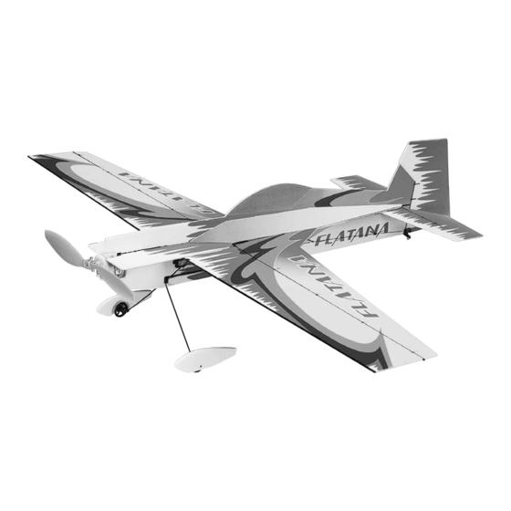
Wingspan: 36 in [915mm]
Wing Area: 241 sq in [15.5 dm
Weight: 7.5 – 9 oz [215-255 g]
Wing Loading: 5 oz/sq ft [13 – 16 g/dm
Length: 31.5 in [800mm]
Radio: 4-channel w/3 micro servos and 10-Amp ESC
Power System: Included ElectriFly
or optional direct-drive RimFire
Great Planes
®
Model Manufacturing Co. guarantees this kit to be free from defects in both material and workmanship at the date of
purchase. This warranty does not cover any component parts damaged by use or modification. In no case shall Great Planes' liability
exceed the original cost of the purchased kit. Further, Great Planes reserves the right to change or modify this warranty without notice.
In that Great Planes has no control over the final assembly or material used for final assembly, no liability shall be assumed nor
accepted for any damage resulting from the use by the user of the final user-assembled product. By the act of using the user-assembled
product, the user accepts all resulting liability.
If the buyer is not prepared to accept the liability associated with the use of this product, the buyer is advised to return this
kit immediately in new and unused condition to the place of purchase.
To make a warranty claim send the defective part or item to Hobby Services at the address below:
Include a letter stating your name, return shipping address, as much contact information as possible (daytime telephone number, fax
number, e-mail address), a detailed description of the problem and a photocopy of the purchase receipt. Upon receipt of the package
the problem will be evaluated as quickly as possible.
READ THROUGH THIS MANUAL BEFORE STARTING
CONSTRUCTION. IT CONTAINS IMPORTANT WARNINGS
AND INSTRUCTIONS CONCERNING THE ASSEMBLY
AND USE OF THIS MODEL.
© Copyright 2005
INSTRUCTION MANUAL
2
]
2
]
™
ferrite motor with gearbox,
™
Brushless motor
3002 N. Apollo Dr., Suite 1
Champaign, IL 61822 USA
WARRANTY
Hobby Services
Champaign, Illinois
(217) 398-8970, Ext 5
airsupport@greatplanes.com
GPMZ0170 for GPMA1111 V1.0
By Great Planes
Advertisement
Table of Contents

Subscribe to Our Youtube Channel
Related Manuals for GREAT PLANES FlatOut Flatana


Summary of Contents for GREAT PLANES FlatOut Flatana
-
Page 1: Instruction Manual
Further, Great Planes reserves the right to change or modify this warranty without notice. In that Great Planes has no control over the final assembly or material used for final assembly, no liability shall be assumed nor accepted for any damage resulting from the use by the user of the final user-assembled product. -
Page 2: Table Of Contents
DECISIONS YOU MUST MAKE ........3 For the latest technical updates or manual corrections to the Transmitter ..............3 FlatOut Flatana ARF visit the Great Planes web site at Servos................3 www.electrifly.com . Open the “Airplanes” link, then select the Receiver...............3 FlatOut Flatana ARF. -
Page 3: Decisions You Must Make
DECISIONS YOU MUST MAKE Low Band High Band (Channels 11-35) (Channels 36-60) In the hands of a capable pilot the FlatOut Flatana ARF is R124F Receiver FUTL0438 FUTL0439 an impressive 3D performer. But for the FlatOut Flatana Crystal... -
Page 4: Battery
(below), a speed control intended for foam-safe CA such as 1 oz. Great Planes Foam Safe Thick CA brushless motors (a brushless speed control) capable of at (GPMR6072). Regular CA is not recommended as it will least 8A continuous current such as the ElectriFly BL-8 aggressively attack the foam used in this model. -
Page 5: Kit Inspection
If any parts are missing or are not of acceptable quality, or if you need assistance with assembly, contact Product Support. When reporting defective or missing parts, use the part names exactly as they are written in the Kit Contents list. Great Planes Product Support: 3002 N. Apollo Drive, Suite 1 Champaign, IL 61822 Telephone: (217) 398-8970, ext. -
Page 6: Ordering Replacement Parts
ORDERING REPLACEMENT PARTS Replacement parts for the Great Planes FlatOut Flatana ARF are available using the order numbers in the Replacement Parts List that follows. The fastest, most economical service can be provided by your hobby dealer or mail-order company. -
Page 7: Build The Airplane
B. Coat both sides of one hinge (C2) with foam-safe CA BUILD THE AIRPLANE where it contacts the sides of the hinge slot. Rotate the hinge down into the slot. Be certain the top and bottom of the hinge remain flush with the top and bottom of the Assemble the Horizontal Tail control surface you are hinging. - Page 8 THE CONTROL SURFACES CLEVISES EASIER Note: You may want to protect your work surface from excess glue. We recommend Great Planes Plan Protector (GPMR6167) for this purpose. A. Cut several 1-1/2" [38mm] pieces of cellophane tape. Fold the last 1/4" [6mm] over to make a tab for easy removal.
-
Page 9: Assemble The Wing
Assemble the Wing ❏ ❏ 1. Cut the wing and ailerons from the foam sheet. 4. Slide four hinge retainer rings (C3) onto the wing trailing edge tube. Position the rings so that they align with the inner slots in the TE of the wing. Secure each retainer with a drop of glue on the outside of the gap. - Page 10 their foam sheets. If using the gearbox included with this kit, or any other type of “stick-mount” gearbox, cut out all four sections from the fuselage parts. If using a firewall- mounted, brushless outrunner motor, cut out only the section from the lower vertical fuselage. ❏...
- Page 11 ❏ ❏ 9. Glue the lower vertical fuselage half to the fuselage 13. Snap the rudder onto the rudder post. tube. Make sure to keep it parallel with the upper half and perpendicular to the horizontal fuselage. ❏ 14. Glue the 3 x 111mm [1/8" x 4-3/8"] strut brace tube into the fuselage.
- Page 12 wing. Two of the supports are at the leading edge (for the fuselage. Make sure that the TE of the wing is aligned with landing gear) and two are at the trailing edge (for the wing the LE, and secure the struts with a drop of glue on both struts).
-
Page 13: Finish The Landing Gear
Finish the Landing Gear ❏ 4. Snap the tailwheel (D5) into the tailwheel bracket (D4). ❏ 1. Install a 2 x 17mm [5/64" x 21/32"] axle and axle support (D1) onto each landing gear leg. Make sure that the axles are perpendicular to the centerline. ❏... - Page 14 ❏ ❏ 4. Install the servo arm on the aileron servo in the 8. Select two single-sided servo arms to fit the elevator position shown. Both arms should be offset forward by the and rudder servos you are using. Insert a Z-bend clevis into same angle.
-
Page 15: Mount The Motor & Gearbox
❏ ❏ 11. Slide two pushrod guides (E3) onto the 1 x 365mm 14. Connect all three servos to the receiver. Mount the [3/64" x 14-3/8"] elevator pushrod and slide the pushrod receiver to the bottom of the left horizontal fuselage with through the clevises on the elevator servo arm and control double-sided foam tape. - Page 16 ❏ 2. Without using any glue, slide the motor mount block over the fuselage tube. Be certain the block is in the correct position so there will be down and right thrust. Do not glue the motor mount block onto the fuselage tube. ❏...
-
Page 17: Firewall-Mounted Motor System
❏ ❏ 9. Install the “hook” side of the included hook-and-loop 3. Use a 220-grit bar sander to lightly sand the front of material to the left side of the fuselage where shown. This is the fuselage even. Be careful not to change the built-in where you will mount the battery. -
Page 18: Get The Model Ready To Fly
Set the Control Throws GET THE MODEL READY TO FLY To simplify setup, the high-rate (3D) control throws for this model are automatically set by the geometry of the included Check the Control Directions hardware. We do recommend, however, that you perform a quick check as described below to make sure the throws are set up correctly. -
Page 19: Balance The Model (C.g.)
weight on the bottom of the fuse until the model balances. Balance the Model (C.G.) Once you have determined the amount of weight required, it can be permanently attached. ❏ More than any other factor, the C.G. (balance point) can 4. -
Page 20: Range Check
5) I will not fly my model unless it is identified with my name Range Check and address or AMA number, on or in the model. Note: This does not apply to models while being flown indoors. Ground check the operational range of your radio before the first flight of the day. -
Page 21: Flying
3-point attitude (nose up at such an angle that all three wheels are level). The FlatOut Flatana ARF is a great-flying model that flies Modulate your descent with the throttle, and use a quick smoothly and predictably. - Page 22 BUILDING NOTES Kit Purchased Date: _______________________ Date Construction Finished: _________________ Where Purchased:_________________________ Finished Weight: __________________________ Date Construction Started: __________________ Date of First Flight: ________________________ FLIGHT LOG...
- Page 24 ANGLE TEMPLATES...
Need help?
Do you have a question about the FlatOut Flatana and is the answer not in the manual?
Questions and answers