Table of Contents
Advertisement
Advertisement
Table of Contents

Related Manuals for American Dynamics ADCI625-P221


Summary of Contents for American Dynamics ADCI625-P221
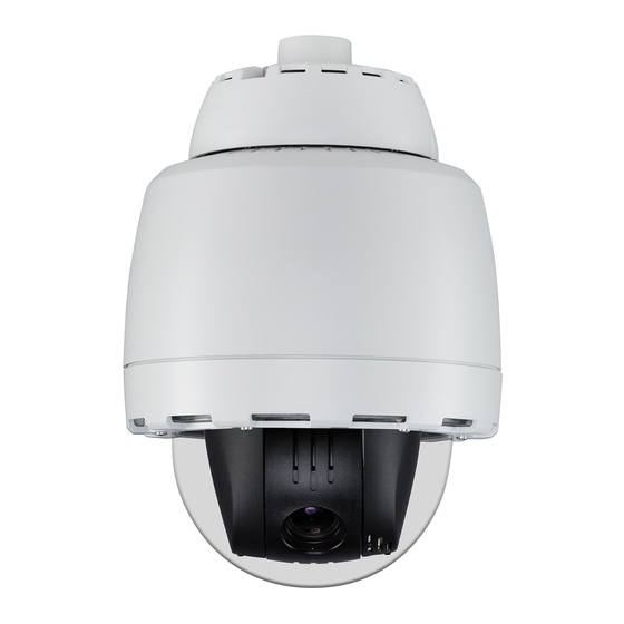
- Page 1 Configuration and User Guide Illustra 625 PTZ Camera 8200-0999-06 B0...
- Page 2 Boca Raton, FL 33487 U.S.A. Customer Service Thank you for using American Dynamics products. We support our products through an extensive worldwide network of dealers. The dealer through whom you originally purchased this product is your point of contact if you need service or support.
-
Page 3: Table Of Contents
Table of Contents Introduction Overview ..............1 Installation Camera Mounts. - Page 4 Table of Contents Controlling the Dome using Camera Controls........15 GUI Camera Controls.
- Page 5 Table of Contents Patterns..............33 Adding a Pattern.
- Page 6 Alarm Video ............66 Integration with American Dynamics Network Video Recorders....66 Integration with other Illustra API Clients .
- Page 7 Table of Contents FTP ..............83 Configuring FTP Server Settings .
- Page 8 Table of Contents Fault Details ............105 DIOM (Digital Input Output Monitor) Component .
- Page 9 Table of Contents Appendix A: User Account Access Appendix B: Site Maps Overview of the Web GUI ...........123 View Menu .
- Page 10 Table of Contents ii-viii Configuration and User Guide...
-
Page 11: Introduction
Illustra 625 PTZ, outdoor, Feature Plus, clear, non-vandal, white ADCi625-P222 Illustra 625 PTZ, outdoor, Feature Plus, clear, vandal, white ADCi625-P221 Illustra 625 PTZ, outdoor, Feature Plus, smoked, vandal, white ADCi625-P223 Illustra 625 PTZ, outdoor, Feature Plus, smoked, non-vandal, white... - Page 12 Introduction Configuration and User Guide...
-
Page 13: Installation
Refer to the Quick Reference Guide supplied with the mount for installation instructions. Please refer to the American Dynamics website or contact your American Dynamics Sales Representative for more information on the various mounts and accessories that can be used with the Illustra 625 PTZ Camera. -
Page 14: Installation Process
Installation Installation Process Configuration and User Guide... -
Page 15: Illustra Connect
Installation Illustra Connect Illustra Connect is American Dynamics camera discovery tool and is supplied with the Illustra 625 PTZ Camera on the CD. Connecting to IP cameras and configuring them can be a time-consuming and error-prone process. Typing static IP addresses, or naming cameras without seeing where they are pointed, often results in longer installations. -
Page 16: Install And Detect The Illustra 625 Ptz Dome
Installation Install and Detect the Illustra 625 PTZ Camera The following provides detailed information for installing and accessing the dome. Installation using DHCP and Illustra Connect The following provides information for installing the dome on your network using the Illustra Connect discovery tool. -
Page 17: Installing The Illustra 625 Ptz Camerausing Dhcp Server Logs
Installation Installing the Illustra 625 PTZ Camera using DHCP Server Logs Procedure 2-2 Installing the Illustra 625 PTZ Camera using DHCP Server Logs Step Action Using the Quick Start Guide install and connect the dome to the computer or network which will be used for the configuration and power on. - Page 18 Installation The dome will begin its initial boot up sequence which will take approximately 1 to 2 minutes. The dome will attempt to obtain an IP Address from the DHCP Server. When no DHCP Server is available the dome will be assigned a Static IP address of 192.168.1.168. Open Microsoft Internet Explorer and enter the URL of the dome as https://192.168.1.168.
-
Page 19: Web Configuration
Web Configuration This section details how to configure the dome using the built-in Web Configuration feature. Depending on user access you can view Live video and control the camera through PTZ controls as well as changing the settings for the camera environment. Note Adobe Reader must be installed to view the online help. -
Page 20: Log In And Log Off The Dome
Web Configuration Log in and Log Off the Dome Logging in to the Dome Use the following procedure to access the dome Web GUI. Procedure 3-1 Log in to the Dome Step Action Refer to the Installation Chapter for details on how to connect the dome to your network or computer. -
Page 21: User Accounts
Web Configuration User Accounts There are three types of user account that can be used to access the dome: • administrator • operator • user Refer to Appendix A: User Account Access for detailed information on access areas. To add a new user refer to Procedure 7-4 Add a User. Administrator Access The administrator account provides full access to the dome. -
Page 22: Accessing The Setup Menus From Full Screen Live View
Web Configuration Figure 3-1 Live Full Screen View Full Screen Live Video Setup Menus GUI Camera Controls Start/Stop Video Volume Control Accessing the Setup Menus from Full Screen Live View Setup menus within the Web GUI are restricted by user account access levels. Procedure 3-3 Access Setup Menus from Full Screen Live View Step Action... -
Page 23: Overview Of The Web Gui
Web Configuration Procedure 3-4 Display Live Video Full Screen Step Action Select Live View in the GUI banner. The live video feed will displayed full screen. Refer to Configuring the Web Video Stream to edit display settings. - End - Overview of the Web GUI Figure 3-2 The Dome Web GUI provides an overview of the Illustra 625 PTZ Web GUI. -
Page 24: Gui Icons
Web Configuration GUI Icons The following provides information on the icons used throughout the dome interface. These icons will be referenced throughout this manual: Select to start the live video Select to stop the live video pane. pane. Check box, deselected. Check box, selected. -
Page 25: Controlling The Dome Using Camera Controls
Web Configuration Procedure 3-5 Viewing Live Video via the Live Video Pane Step Action Select to start the live web video. Refer to Configuring the Web Video Stream to edit display settings. Select to stop the live web video. - End - Controlling the Dome using Camera Controls The dome may be controlled using the on-screen controls in the Live Video Pane. -
Page 26: Controlling The Camera Via Keyboard Shortcuts
Web Configuration Controlling the camera via Keyboard Shortcuts The following keyboard shortcuts can be used to control the dome: Pan Left Pan Right Tilt Up Tilt Down Zoom In Zoom Out Controlling the camera via Camera Controls The dome may be controlled using the on-screen controls in the Live Video Pane. Procedure 3-6 Controlling the camera via the Live Video Pane Step Action... -
Page 27: Zooming Using The Mouse Scroll Wheel
Web Configuration Procedure 3-7 Controlling Pan/Tilt via Click and Drag using the Live Video Pane Step Action Select to start the live web video feed. The live video pane will display the current camera view. Move the cursor to the pan and tilt quick control icon in the center of the video pane. -
Page 28: Ptz To A Selected Area Using The Mouse
Web Configuration The PTZ will adjust to display the area of interest in the center of the live video pane. Repeat step 2 to select a new area of interest. - End - PTZ to a Selected Area using the mouse Draw a rectangle on the live video pane to have the camera PTZ adjust to the selected area of interest. -
Page 29: View Menu
View Menu When the view menu is selected Figure 4-1 View Menu will be displayed. Figure 4-1 View Menu The View Menu provides access to the following dome settings and functions: • Picture Settings • Presets • Patterns • Privacy Zones •... -
Page 30: White Balance
View Menu White Balance White balance (the ability to keep whites looking white) is normally compensated for automatically via the default Auto White Balance (AWB) setting. Manual White Balance (MWB) is available when specific color temperature settings want to be set and preserved. This can be done using the red and blue slider adjustments set for optimal viewing. -
Page 31: Picture Balance
View Menu Use the slider bars to change the Red and Blue balance. The live video pane will update to display the new settings. The red and blue values range from 0% to 100%. - End - Picture Balance Adjust brightness, contrast and saturation of the image displayed in the Live Video Pane. Adjusting Picture Balance Configure brightness, contrast and saturation. -
Page 32: Focus/Iris
View Menu Procedure 4-4 Restore Picture Balance Defaults Step Action Select Picture Settings from the View menu. Select the Picture Balance tab. The Picture Balance tab displays. Select Defaults to restore the default settings. The default settings are 50%. - End - Focus/Iris When Auto Focus and Iris are enabled the camera automatically compensates for scene changes that effect focal length (focus) and light levels (iris). -
Page 33: Setting Auto Iris
View Menu Setting Auto Iris Enable or disable auto iris on the dome. Procedure 4-6 Enable/Disable the Dome Auto Iris Step Action Select Picture Settings from the View menu. Select the Focus/Iris tab. The Focus/Iris tab displays. Select the Auto Iris check box to enable auto iris. Deselect the Auto Iris check box to disable auto iris. -
Page 34: Ir/Daynight Mode
View Menu IR/DayNight Mode IR/DayNight Mode utilizes a series of specific camera functions to dramatically enhance low light performance. When needed one of these functions, the True TDN mechanism, removes an IR Cut Filter (IRCF) from in front of the imager allowing the camera to see in black and white (BW) and utilize additional near-infrared energy found in many lighting sources like halogen, moonlight, etc. -
Page 35: Day Night Mode
View Menu • visible - Most common, visible lighting sources. • 850nm - Ideal for 850nm IR Illuminators. • 950nm - Ideal for 950nm IR Illuminators. The default setting is ‘visible’. - End - Day Night Mode The dome provides a black-and-white (B/W) mode to improve camera performance when the light level falls below certain thresholds. -
Page 36: Automatic Gain Control (Agc)
View Menu Automatic Gain Control (AGC) Amplifies the video signal in scenes when there is not enough light to produce full video levels. The maximum level of AGC is controlled by the Max Gain control. It is adjustable from 0dB (off) to 37dB. -
Page 37: Shutter Speed
View Menu Shutter Speed Changing the Shutter Speed Selecting a fast shutter speed will give the least amount of artifacts but reduced low light performance, a slower shutter speed will give better low light performance but more artifacts will be visible. Procedure 4-11 Configure Shutter Speed Step Action... -
Page 38: Picture Settings
View Menu Procedure 4-12 Configure Max Gain Step Action Select Picture Settings from the View menu. Select the Shutter Limit tab. The Shutter Limit tab displays. When ‘AGC on’ or ‘openshutter’ is selected from the AGC/Shutter Setting the Max gain section will be displayed. -
Page 39: Restoring Saved Picture Settings
View Menu Restoring Saved Picture Settings Restore previously saved picture settings. Procedure 4-14 Restore Saved Picture Settings Step Action Select Picture Settings from the View menu. Select the Picture Settings tab. The Picture Settings tab displays. Select Restore to restore the previously saved picture settings. - End - Restoring Factory Default Picture Settings Restore the factory default picture settings. -
Page 40: Presets
View Menu Presets A Preset is a pre-positioned camera scene that you program for cameras installed with pan/tilt and motorized lens capability. Up to 96 presets can be programmed for the dome. Adding a new Preset Create a new preset position on the dome. Procedure 4-16 Add a Preset Step Action... -
Page 41: Editing A Preset
View Menu Procedure 4-17 View a Preset Step Action Select Presets from the View menu. The Preset tab displays. Select to start the live web video. The live video pane will display the current camera view. Select to activate the corresponding preset. The live video pane will update to display the selected preset.The preset will display until interrupted by a camera command, pattern, scan or alarm. -
Page 42: Deleting A Preset
View Menu • White Balance • Picture Balance • Wide Dynamic Range (WDR) • IR/DayNight • Shutter Limit Select Add to save the updated preset. You will be prompted to confirm the update. Select OK to save the changes. Select Cancel. - End - Deleting a Preset Delete an existing preset position from the dome. -
Page 43: Patterns
View Menu Patterns A pattern is a series of pan, tilt, zoom and focus movements which can be saved to the dome. A maximum of 17 patterns can be programmed for the dome with an unlimited duration. Note The Illustra 625 PTZ provides Apple Peel, which is a predefined pattern stored on the camera by default that covers the entire viewing area. -
Page 44: Running A Pattern
View Menu Select Cancel. - End - Running a Pattern Activate an existing pattern. Procedure 4-21 Run a Pattern Step Action Select Patterns from the View menu. The Patterns tab displays. Select to start the live web video feed. The live video pane will display the current camera view. Select to activate the corresponding pattern. -
Page 45: Repeating A Pattern
View Menu Select Cancel. - End - Repeating a Pattern Use this procedure to have a pattern repeat until interrupted by a new command. Procedure 4-23 Enable/Disable Repeat a Pattern Step Action Select Pattern from the View menu. The Patterns tab displays. Select the Repeat tab. -
Page 46: Privacy Zones
View Menu Privacy Zones Privacy Zones are “masked” sections of the dome’s viewing area. These masks prevent operators of the surveillance system who do not have access to the dome password from viewing these designated zones. Each zone has four sides, and the zones may overlap to form irregular shapes. The Privacy Zones move in relation to the dome pan/tilt position. -
Page 47: Enabling Or Disabling A Privacy Zone
View Menu Select Cancel. Note When a new privacy zone is created it is automatically enabled, refer to Procedure 4-25 Enable/Disable a Privacy Zone to modify this setting. - End - Enabling or Disabling a Privacy Zone Select a privacy zone to hide or display on the dome. Procedure 4-25 Enable/Disable a Privacy Zone Step Action... - Page 48 View Menu Select the corresponding Delete check box to mark the privacy zone for deletion. Note More than one privacy zone can be deleted at a time. The Select All check box can also be used. Select Delete to delete the selected privacy zones. You will be prompted to confirm the deletion.
-
Page 49: Scans
View Menu Scans A scan allows you to program left and right scan limits to automate surveillance activities. Once these scan limits are programmed you can choose to run a smooth scan, stepped scan, or random scan. When active, the scan repeats until interrupted by a camera command, preset, pattern or alarm. -
Page 50: Activating A Scan
View Menu The scan limits will default to Left: 0 and Right: 359. - End - Activating a Scan Activate a scan on the dome, this will run using the scan limits saved in Setting Scan Limits. Procedure 4-29 Activate a Scan Step Action Refer to Setting Scan Limits before activating a scan. -
Page 51: Programs Menu
Programs Menu When the view menu is selected Figure 5-1 Programs Menu will be displayed. Figure 5-1 Programs Menu The Programs Menu provides access to the following dome settings and functions: • Sequences • Alarms • Scheduled Tasks • Areas 5-41... -
Page 52: Sequences
Programs Menu Sequences A Sequence is a sequential display of multiple camera Presets. Sequences provide a methodical and effective way to monitor multiple areas of interest by switching to different Presets automatically. Sequences are created by identifying Preset views to include in the Sequence and specifying a dwell time that controls how long each Preset remains on-screen before switching to another Preset. -
Page 53: Editing A Sequence
Programs Menu Procedure 5-2 Activate a Sequence Step Action Select Sequences from the Programs menu. The Sequences tab displays. Select to start the live web video feed. The live video pane will display the current camera view. Select to activate the corresponding sequence. The live video pane will update to display the selected sequence.The sequence will run continuously until interrupted by a camera command, pattern, preset, scan or alarm. -
Page 54: Deleting A Sequence
Programs Menu Deleting a Sequence Delete an existing sequence. Procedure 5-4 Delete a Sequence Step Action Select Sequences from the Programs menu. The Sequences tab displays. Select to delete the corresponding sequence. You will be prompted to confirm the deletion. Select OK to confirm the deletion. -
Page 55: Alarms
Programs Menu Alarms If using a Illustra 625 PTZ Feature Plus camera it will be possible to configure and trigger alarms. The dome can be commanded to carry out a specified operation when a alarm is triggered. Note Scheduled tasks, return to home, alarms and manual camera control will always begin when they are selected or scheduled to start. -
Page 56: Creating An Alarm
Programs Menu • Send an AVI video file to a pre-configured external FTP server. The video file will contain pre and post alarm video buffer and audio if enabled and supported, as outlined above. Note An active internal alarm only resets when the input state changes to “normal.” A manual reset is not available. -
Page 57: Enabling Or Disabling An Alarm
Programs Menu Select the FTP check box to send a video file to the details configured in Procedure 7-9 Configure FTP Server Settings. Note AVI clips can only be sent via FTP if a microSD card has been installed and FTP has been selected. -
Page 58: Enable Or Disable Alarm Output
Programs Menu Enable or Disable Alarm Output Alarm Output allows the alarm to activate a digital output as an action. For example, this digital output could be linked to an electrical device, i.e. a security light or siren. Procedure 5-7 Enable/Disable Alarm Output Step Action Select Alarm from the Programs menu. -
Page 59: Clearing Alarm Output Logs
Programs Menu Step Action Select Current Faults from the Information menu. The Current Faults tab displays with a list of current faults found on the dome. Alarms will be listed under the Component heading of DIOM. - End - Clearing Alarm Output Logs When an alarm is triggered it registers on the dome in the Current Faults table. -
Page 60: Inserting The Microsd Card
Programs Menu Inserting the MicroSD Card When inserting a MicroSD card it is essential that the camera is rebooted. If at any stage you need to insert a MicroSD card into the camera one of the following two procedures should be used: •... - Page 61 Programs Menu • Unmount the MicroSD Card for Removal - Use this procedure when you are unable to access the power supply to the camera. Note If the Illustra 625 PTZ Camera is being used with the Outdoor Housing Assembly or Indoor Housing Assembly, refer to the Quick Reference Guide supplied with the product for details on how to remove the housing assembly and gain access to the camera.
- Page 62 Programs Menu Remove the MicroSD card from the camera. Note AVI clips will not be available on the camera until the MicroSD card has been inserted and the camera rebooted. - End - 5-52 Configuration and User Guide...
-
Page 63: Scheduled Tasks
Programs Menu Scheduled Tasks Schedule tasks to include specific situations or events; you can set up a regular schedule or a custom schedule. Schedules could be set for the dome to perform a task, Monday to Friday with a different task for weekend or holiday operation. Note Scheduled tasks, alarms and manual camera control will always begin when they are selected or scheduled to start. -
Page 64: Editing A Scheduled Task
Programs Menu Select the Scheduled Tasks tab to display a list of tasks currently set on the dome. - End - Editing a Scheduled Task Edit the details for an existing scheduled task. Procedure 5-15 Edit a Scheduled Task Step Action Select Scheduled Tasks from the Programs menu. - Page 65 Programs Menu Select Delete to delete the selected scheduled tasks. You will be prompted to confirm the deletion. Select OK to confirm the deletion. Select Cancel. - End - 5-55...
-
Page 66: Areas
Programs Menu Areas Areas allow sections within the field of view to be labeled. These labels may then be turned on within the Overlay Settings option. Areas may not overlap. The zoom level affects the size areas may appear. You may program up to 16 areas on the dome. Programming an Area Set an area on the dome. -
Page 67: Deleting An Area
Programs Menu Procedure 5-18 Editing Areas Step Action Select Areas from the Programs menu. The Areas tab displays. Select to edit the corresponding area. Changes can be made to the following: • Name • Left boundary • Right boundary Select Add to save the changes to the area. Select Cancel. - Page 68 Programs Menu 5-58 Configuration and User Guide...
-
Page 69: Camera Configuration Menu
Camera Configuration Menu When the Camera Configuration menu is selected Figure 6-1 Camera Configuration Menu will be displayed. Figure 6-1 Camera Configuration Menu The Camera Configuration Menu provides access to the following dome settings and functions: • Pan/Tilt/Zoom (PTZ) • On Screen Display (OSD) •... -
Page 70: Ptz
Camera Configuration Menu The PTZ function allows you to adjust Automatic Flip, Freeze Frame, Return Settings and Set North. Adjusting Automatic Flip Use the automatic (proportional) “flip” feature when you need to track someone who walks directly under the dome and continues on the other side. You start the flip by moving the tilt control to its lower limit and holding for a brief period. -
Page 71: Return Settings
Camera Configuration Menu The default setting is ‘Disabled’. - End - Return Settings When calling a Preset, the dome adopts the settings uniquely created for that Preset. When an operator moves the dome from its Preset position, the dome can return to global settings only if programmed to do so through the Return Setting page. - Page 72 Camera Configuration Menu Adjust the camera view as required to locate the north position. Refer to GUI Camera Controls to make the necessary adjustments. Select Set North to save the current view as the north position. - End - 6-62 Configuration and User Guide...
-
Page 73: On-Screen Display (Osd)
Camera Configuration Menu On-Screen Display (OSD) Within OSD you can set the display options for camera name, status, settings names, time/direction indicators and text attributes. Displaying the Camera Name The camera name will be shown on the on-screen display (OSD) if the option is enabled. Procedure 6-5 Display or Hide the Camera Name Step Action... -
Page 74: Displaying Dome Names
Camera Configuration Menu Displaying Dome Names You can choose to display the area, preset, pattern and alarm names on the on screen display when they are active. Procedure 6-7 Display or Hide the Dome Names Step Action Select OSD from the Camera Configuration menu. Select the Dome Names tab. -
Page 75: Configuring Text Attributes
Camera Configuration Menu The default setting for all functions is ‘Disabled’. - End - Configuring Text Attributes Choose whether to display text as translucent (slightly clear) or solid. If on-screen text obscures the video being displayed, enable translucent names. Character outlines and translucent names may be used together to best suit your video environment. -
Page 76: Video
It is possible to use either Stream 1 or Stream 2 for the on-board recording of alarm video. Integration with American Dynamics Network Video Recorders Stream 1 and Stream 2 can be configured via the Web GUI, as detailed here or via the Network Video Recorder interface. -
Page 77: Configuring The Web Video Stream
Camera Configuration Menu Resolution Recommended Maximum Quality 1280x720 1280x720 Configuring the Web Video Stream Adjust the settings for video displayed on the live video pane and video used for alarms. Procedure 6-10 Configure the Video Stream settings Step Action Select Video from the Camera Configuration menu. The Stream 1 tab displays. -
Page 78: Select The Alarm Video Stream
Camera Configuration Menu • VBR (Variable Bit Rate) • CBR (Constant Bit Rate) The default setting is ‘VBR’. If VBR has been selected, VBR Quality will be enabled. Select the required VBR Quality from the drop-down menu. •Highest •High •Medium •Low •Lowest... - Page 79 Camera Configuration Menu The selected stream will be used for video generated from an alarm. - End - 6-69...
-
Page 80: Audio
Camera Configuration Menu Audio Allows you to configure the audio input, output, upload audio and stored audio clips. Note Audio is only available on the Illustra 625 PTZ Feature Plus Model. Configuring Audio Input Configure the audio input settings. Procedure 6-12 Configure Audio Input Step Action Select Audio from the Camera Configuration menu. -
Page 81: Configuring Stored Audio
Camera Configuration Menu Select the Output Enable check box to enable the audio output settings. Audio output settings will only be available is audio output is selected. Deselect the Output Enable check box to disable audio input settings. The default setting is ‘Disabled’. If Output Enable has been enabled, use the slider bar to select the Output Volume. -
Page 82: Deleting A Stored Audio File
Camera Configuration Menu Procedure 6-15 Upload a Audio File Step Action Select Audio from the Camera Configuration menu. Select the Upload Audio tab. The Upload Audio tab displays. Select Browse. The Choose file dialog will be displayed. Navigate to the location where the audio file has been saved. Select the audio file then select the Open button. - Page 83 Camera Configuration Menu Deselect the corresponding Delete check box to keep the audio file. Note Select the Select All check box to mark all audio files for deletion. Select Delete to delete the selected audio files. You will be prompted to confirm the deletion. Select OK to confirm the deletion.
-
Page 84: Home
Camera Configuration Menu Home The home position is a preset, pattern or scan/sequence that automatically runs after a designated period of dome inactivity. Use this option if you want to keep a specific area under surveillance when the dome is not moving. Setting a Home Position Use a home position on the dome. -
Page 85: Networking Menu
Networking Menu When the Networking menu is selected Figure 7-1 Networking Menu will be displayed. Figure 7-1 Networking Menu The Networking Menu provides access to the following dome settings and functions: • TCP/IP • Date & Time • User Accounts •... -
Page 86: Tcp/Ip
Networking Menu TCP/IP Configure the IPv4 and IPv6 settings on the dome. IPv4 Set IPv4 settings for the dome. Procedure 7-1 Configure the IPv4 Settings Step Action Select TCP/IP from the Networking menu. The IPv4 tab displays. Select the Enable DHCP check box to enable DHCP and disable manual settings entry. Deselect to disable DHCP and allow manual settings entry. - Page 87 Networking Menu The default setting is ‘enabled’. If IPv6 is enabled the Link Local and DHCP address will be displayed if available. - End - 7-77...
-
Page 88: Date Time
Networking Menu Date Time Set the date and time format. Setting Date Time Change the date and time settings on the dome. Procedure 7-3 Configuring the Date and Time Step Action Select Date Time from the Networking menu. The Date Time tab displays. Select the Time 24-hour check box to enable the 24-hour clock. -
Page 89: Users
Networking Menu Users In this section you are able to add and delete user accounts. There are three levels of access: admin, operator and user. Refer to Appendix A: User Account Access for details on the access rights of each account. Add User Add a new user account to allow access to the dome. -
Page 90: Delete A User Account
Networking Menu The Change Password tab displays. Select the user account from the Name drop-down menu. Enter the current password for the user account in the Current Password text box. Enter the new password for the user account in the New Password text box. The password is case sensitive and can contain alphanumeric characters with a length of between 4 and 32 characters. -
Page 91: Smtp
Networking Menu SMTP Configure the SMTP settings to allow e-mail alerts to be sent from the dome when an alarm is triggered. Configure SMTP SMTP settings must be configured to enable email alerts when using alarms. Procedure 7-7 Configure SMTP Settings Step Action Select SMTP from the Networking menu. - Page 92 Networking Menu Procedure 7-8 Test the SMTP Settings Step Action Select SMTP from the Networking menu. The SMTP tab displays. Select Test. A sample email will be sent to the specified email address to confirm that SMTP settings are correct. The dome will display a message confirming that the transfer was either successful or failed.
-
Page 93: Ftp
Networking Menu Configure the FTP settings for the FTP server. Configuring FTP Server Settings FTP must be configured to enable FTP alerts when using alarms. Procedure 7-9 Configure FTP Server Settings Step Action Select FTP from the Networking menu. The FTP tab displays. Enter the IP address of the FTP Server in the FTP Server text box. - Page 94 Networking Menu The FTP tab displays. Select Test. A sample text file will be sent to the specified FTP destination to confirm that FTP settings are correct. - End - 7-84 Configuration and User Guide...
-
Page 95: Firewall
Networking Menu Firewall Configure the Basic Filtering and Address Filtering for the Firewall. Basic Filtering Enable or disable basic filtering for the dome this includes, ICMP Blocking, RP Filtering, SYN Cookie Verification. Procedure 7-11 Enable/Disable Basic Filtering Step Action Select Firewall from the Networking menu. The Basic Filtering tab displays. -
Page 96: Editing An Address Filter
Networking Menu Deselect the Address Filtering check box to disable address filtering. The default setting is ‘Disabled’. If address filtering has been enabled: Enter an IP or MAC Address in the IP or MAC Address text box in the following format xxx.xxx.xxx.xxx. - Page 97 Networking Menu Procedure 7-14 Delete an Address Filter Step Action Select Firewall from the Networking menu. Select the Address Filtering tab. The Address Filtering tab displays. Select to delete the corresponding address filter. Select Apply to confirm the deletion. - End - 7-87...
-
Page 98: Maintenance
Networking Menu Maintenance Backup, restore, upgrade the firmware, perform a reboot or return to factory defaults from this section. Backup/Restore Backup camera data and restore from a previously saved data file. Save Camera Data The configuration settings of the dome can be saved to a data file. The data file can be saved to a specified location and used to restore the dome configuration. -
Page 99: Upgrade Camera Firmware
All existing camera settings are maintained when the firmware is upgraded. Caution You should only use firmware that has been provided by American Dynamics. Using any other firmware may cause a malfunction and damage the dome. Procedure 7-17 Upgrade Camera Firmware... -
Page 100: Upload A Https Certificate
Networking Menu Select Cancel. When the dome is restarted it checks its functionality by performing a homing routine during which the camera pans and then either goes to the start point of the ‘apple peel’ pattern or if powered up once before, to the last position in memory. Once the camera stops, it is online and ready to be accessed and controlled. -
Page 101: Rebooting The Dome
Networking Menu Procedure 7-19 Delete a HTTPS Certificate Step Action Select Maintenance from the Networking menu. Select the HTTPS Certificate tab. The HTTPS Certificate tab displays. Select Delete. The camera will display a “Restarting HTTPS Service” page with a progress bar showing the deletion progress. -
Page 102: Reset The Dome To Factory Default Settings
Networking Menu Reset the Dome to Factory Default Settings Restore the settings on the dome to factory default. Note Network settings, presets, patterns and sequences can be retained if required. Procedure 7-21 Resetting the dome Step Action Select Maintenance from the Networking menu. Select the Reset tab. -
Page 103: Physical Reboot/Reset Of The Dome
Networking Menu Physical Reboot/Reset of the Dome It is possible for perform a physical reboot or reset to factory defaults using the reset/reboot switch located on the dome, refer to Figure 7-2 Reset/Reboot Switch on the Dome. Note To perform a physical reboot or reset, access is required to the dome itself. If the dome is being used in an Outdoor Housing or with the Indoor Housing Assembly, refer to the quick start guides supplied with the products for details on how to remove the bubble and gain access to the dome. -
Page 104: Resetting The Dome To Factory Default Settings Using The Reset/Reboot Switch
Networking Menu Resetting the Dome to Factory Default Settings using the Reset/Reboot Switch The reset/reboot switch can be used to restore the dome to the factory default settings. Note It is not possible to retain network settings, presets, patterns or sequences when using this procedure. -
Page 105: Advanced Settings
Networking Menu Advanced Settings Configure the camera name, bandwidth throttling, session timeout and remote access on the dome. Camera Name The camera name will be displayed on the GUI banner and the on-screen display for the dome. Procedure 7-24 Edit the Camera Name Step Action Select Advanced Settings from the Networking menu. -
Page 106: Remote Access
Remote Access SSH Enable Enables Secure Shell access into the dome, if remote access is permitted by the camera network. This will also enable American Dynamics Level 3 Technical Support to diagnose any problems on the dome. Note t is recommended to keep SSH Enable disabled. This function should only be enabled this when it is requested by American Dynamics Level 3 Technical Support. -
Page 107: Onvif User Authentication
Networking Menu Procedure 7-27 Enable/Disable ONVIF Discovery Mode Step Action Select Advanced Settings from the Networking menu. Select the Remote Access tab. The Remote Access tab displays. Select the ONVIF Discovery Mode check box to enable ONVIF Discovery Mode. Deselect ONVIF Discovery Mode check box to disable ONVIF Discovery Mode. The default setting is ‘Enabled’. - Page 108 Networking Menu Procedure 7-29 Configure Dynamic DNS Step Action Select Advanced Settings from the Networking menu. Select the Dynamic DNS tab. The Dynamic DNS tab displays. Select the Service Enable check box to enable Dynamic DNS. Deselect Service Enable check box to disable Dynamic DNS. The default setting is ‘Disabled’.
-
Page 109: Information
Information When the Information menu is selected Figure 8-1 Information Menu will be displayed. Figure 8-1 Information Menu The Information Menu provides access to the following dome information: • Model • Statistics • Environmental • Logs • Current Faults 8-99... -
Page 110: Model
Information Model Model Information When Model is selected information will be displayed on the following: • Camera Name • Model • Product Code • Manufacturing Date • Serial Number • MAC Address • Firmware Version • Hardware Version Procedure 8-1 Display Model Information Step Action Select Model from the Information menu. -
Page 111: Statistics
Information Statistics General Information When General Information is selected information will be displayed on the following: • Operating Time (days-hrs:mins) • Uptime (days-hrs:mins) • User Resets • Power Resets • Total ROM (MByte) • Total RAM (MByte) • Free RAM (MByte) Procedure 8-2 Display General Information Step Action... -
Page 112: Environmental
Information Environmental Environmental Information When Environmental is selected information will be displayed on the following: • Internal Temperature • Blower • Heater • Firmware Version Procedure 8-4 Display General Information Step Action Select Environmental from the Information menu. The Environmental tab displays. - End - 8-102 Configuration and User Guide... -
Page 113: Logs
Select Refresh to refresh the log for the most up-to-date information. - End - Boot Log The Boot log is a log of the Linux operating system boot processes and will only be useful to American Dynamics support engineers who require additional information on the device. 8-103... - Page 114 Information Procedure 8-7 Display Boot Log Step Action Select Logs from the Information menu. Select the Boot Log tab. The Boot Log tab displays. Select Refresh to refresh the log for the most up-to-date information. - End - Procedure 8-8 Boot Log Filter Step Action Select Logs from the Information menu.
-
Page 115: Current Faults
Information Current Faults Current Faults When Current Faults is selected information will be displayed on the following: • # - details the fault index. • Fault - a description of the fault. • Date created - the time and date when the fault occurred. •... - Page 116 Information • TemperatureTooHigh (Warning) - this fault is raised when the internal temperature of the enclosure is equal to or exceeds the value MAX_TEMPERATURE held in ENVM.conf. Once an alarm is generated and the temperature drops to a level 1 degree below the MAX_TEMPERATURE value the fault is then automatically cleared.
-
Page 117: Viewing Alarm Output
Information Viewing Alarm Output Procedure 8-11 View Alarm Output Step Action Select Current Faults from the Information menu. The Current Faults tab displays. Select the Alarm Output tab. The Alarm Output tab displays. - End - Clearing an Alarm Output Clear an alarm output from the dome if it has been triggered. - Page 118 Information 8-108 Configuration and User Guide...
-
Page 119: Technical Specifications
Technical Specifications This section provides information on the technical, environmental and operating specifications for the i625PTZ dome. Basic Summary of Features • Mega pixel HD 1080p Resolution 30fps, 20X Optical zoom • Progressive scan with square pixels • Camera set-up •... -
Page 120: Technical Details
Technical Specifications Specification Detail Focal Length 4.7mm~94mm (wide~telephoto) Zoom and Pan Accuracy +/- 0. 5° Preset access Time Less than 1 second to position. Full zoom position in < 4 seconds. Focus on saved presets is < 1 second. Areas Privacy Zones Alarm Inputs Auxiliary Output... -
Page 121: Video Compression
Technical Specifications Video Compression Category Details Codec Streams 2 any codec, resolution quality/bit rate settings IP Video Streams 4 maximum including codec sharing duplicate streams Resolutions (1920 x 1080) 1080p (1600 x 900) HD+ (1280 x 720) 720p (1024 x 576) PAL+ (960 x 540) qHD (800 x 450) (640 x 360) nHD... -
Page 122: Base Protocol And Underlying Layers
Technical Specifications Category Details Data Transmission HTTP - RFC2616 FTP - RFC959 Network Address Configuration DHCP - RFC2131 Zeroconf - RFC3927 Static IP address Network Name Resolution DNS - RFC5395 DDNS - RFC 2136 Time Synchronization NTP - RFC1305 IETF NTP Working Group i minute poll rate E-mail SMTP - RFC5321... -
Page 123: Network Address Configuration
SMTP server. Remote Shell Access For security reason, remote shell access is limited exclusively to American Dynamics Level 3 Technical Support. This function is not available to the end-user. t is recommended to keep SSH Enable disabled. This function should only be enabled this when it is requested by American Dynamics Level 3 Technical Support. -
Page 124: Onvif Video And Control Interface
Technical Specifications ONVIF Video and Control Interface The primary video and control interface to the dome is the Open Network Video Interface Forum global standard for the interface of network video products. This uses SOAP over HTTP. The dome provides ONVIF for integration to internal and external systems. Interface Technical Specifications Category Details... -
Page 125: Onvif Functions Not Supported
Technical Specifications • Reboot • Get/set/remove scope (assigns ID data) • Fault codes Security Configure Video and Audio • Video Source • Audio Source • Snapshot JPEG PTZ Functions • Get PTZ Configurations • Get PTZ Configuration Options • Set PTZ Configuration •... -
Page 126: Microsd Card
Technical Specifications microSD Card External access is provided for a microSD for video alarm storage and audio output pre-recorded clips. The maximum size of microSD card that can be used with the dome is 32GB. Refer to the Quick Reference Guide provided with the dome for information on how to remove and install the microSD Card. -
Page 127: Surge Protection
Technical Specifications Category Details Connector Pluggable Euro-style pin 3.5 terminal block connector Design Tolerance Input minimum:19 VAC RMS without dropout Input Maximum:Voltage >35 VAC RMS may damage equipment Line Frequency:47-63 Hz Allowable drop out:30 ms Surge Protection The following applies: Category Details Power Line... - Page 128 Technical Specifications 9-118 Configuration and User Guide...
-
Page 129: Appendix A: User Account Access
Appendix A: User Account Access Camera Menu Function Admin Operator User View Picture Settings White Balance Picture Balance Focus/Iris IR/DayNight Shutter Limit Picture Settings Presets Presets List View Edit Delete Patterns Patterns List View Edit Delete Record Repeat Privacy Zones Privacy Zones List Enable/... - Page 130 Appendix A: User Account Access Camera Menu Function Admin Operator User Edit List Edit List Edit List Edit List Edit Scheduled Tasks Scheduled Tasks List Edit Delete Add Task Area Areas List Edit Delete Camera Configuration Flip Freeze Frame Return Settings Set North Name Status...
- Page 131 Appendix A: User Account Access Camera Menu Function Admin Operator User Edit IPv6 List Edit Date Time Date Time List Edit Users Users List Delete Add User Change Password SMTP SMTP List Edit Test List Edit Test Firewall Basic Filtering List Edit Address Filtering...
- Page 132 Appendix A: User Account Access 10-122 Configuration and User Guide...
-
Page 133: Appendix B: Site Maps
Appendix B: Site Maps Overview of the Web GUI 11-123... -
Page 134: View Menu
Appendix B: Site Maps View Menu 11-124 Configuration and User Guide... -
Page 135: Programs Menu
Appendix B: Site Maps Programs Menu 11-125... -
Page 136: Camera Configuration
Appendix B: Site Maps Camera Configuration 11-126 Configuration and User Guide... -
Page 137: Networking
Appendix B: Site Maps Networking 11-127... -
Page 138: Information
Appendix B: Site Maps Information 11-128 Configuration and User Guide... -
Page 139: Appendix C: Using Vlc Player To View Rtsp Streaming
Appendix C: Using VLC Player to View RTSP Streaming Note This appendix is provided for user instruction only. American Dynamics will not support or be responsible for any error caused during the use of VLC software. Viewing RTSP Stream via VLC Player You can use VLC Player to view live video and audio in real time from the dome. -
Page 140: Retrieving The Rtsp Address From The Dome
Appendix C: Using VLC Player to View RTSP Streaming Retrieving the RTSP Address from the Dome Use this procedure if you are unsure which codec settings are being utilized by the dome. Procedure 12-2 Retrieve RTSP Address from the Dome Step Action Open Microsoft Internet Explorer. -
Page 141: Configuration Options For Rtsp Video Streams
Appendix C: Using VLC Player to View RTSP Streaming Configuration Options for RTSP Video Streams The following provides examples on how to configure the RTSP Video Stream: Video using a MJPEG codec • rtsp://<ip address>/Video?Codec=MJPEG Video at 640x360 using a MJPEG codec @30 FPS with No Audio •... - Page 142 Appendix C: Using VLC Player to View RTSP Streaming 12-132 Configuration and User Guide...
Need help?
Do you have a question about the ADCI625-P221 and is the answer not in the manual?
Questions and answers