Table of Contents
Advertisement
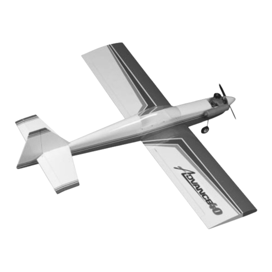
INSTRUCTION MANUAL
Specifications
Wingspan:
Fuselage Length:
Wing Area:
. . . . . . . . . . . . . . . . . . . . . . . . . . . . . .
Flying Weight (Approx.):
Recommended Engines:
WE GET PEOPLE FLYING
• Quick assembly
• Modular construction allows for easily replaced parts if crash damaged
• Pre-covered and trimmed in genuine UltraCote
• All balsa plywood craftsmanship constructed
60
. . . . . . . . . . . . . . . . . . . . . . . . . . . . . . . . . . . . . .
50
. . . . . . . . . . . . . . . . . . . . . . . . . . . . . . .
664 sq. in.
5
1
/
–6
1
/
lbs.
. . . . . . . . .
2
4
. . . . . . . . . . . . . . . . . . . . . . . . . . . . . . . .
TM
TM
''
1524mm
. . . . . . . . . . . . . . .
''
1270mm
. . . . . . . . . . . . . . .
4284 sq cm
. . . . . . . . . . .
2495–2835 grams
. .
.40–.48 2-stroke
V1.1
®
Advertisement
Table of Contents

Related Manuals for Hangar 9 Advance 40


Summary of Contents for Hangar 9 Advance 40
- Page 1 WE GET PEOPLE FLYING INSTRUCTION MANUAL V1.1 • Quick assembly • Modular construction allows for easily replaced parts if crash damaged ® • Pre-covered and trimmed in genuine UltraCote • All balsa plywood craftsmanship constructed Specifications ′′ Wingspan: 1524mm ....
-
Page 2: Table Of Contents
Balancing the Advance 40 ........ -
Page 3: Introduction
The epoxy is used to join the main wing panels. For newer flyers, the Advance 40 is the perfect follow-up to the Easy 2. More experienced flyers will find the Advance 40 to be a quick way to get in the air fast with a high-quality, all-wood UltraCote-covered airplane that even the most discriminating pilot would be proud to show off. -
Page 4: Additional Parts Needed
Additional Parts Needed to Assemble the Advance 40: • Phillips screwdriver • .40–.48 2-cycle engine with muffler • .50–.56 4-cycle engine with muffler (modification to throttle pushrod and engine mount may be necessary if used) • 4-channel or greater radio system with four standard servos (JR 400 with four 507 servos recommended) •... -
Page 5: Advance 40 Parts Layout
Advance 40 Parts Layout A. Fuselage M. Rubber bands B. Left wing N. Wing brace C. Right wing O. Shock-Loc™ tray D. Screws to mount canopy P. Main landing gear E. Vertical stabilizer with rudder Q. Canopy F. Main wheels R. -
Page 6: Stage 1-Assembling The Wing
• Masking tape shortest two linkages in the kit • Wax paper (optional) • Aileron connectors (2) Note: On some Advance 40 kits, • Fuel tubing pieces (5mm long) (2) these may already be attached to the aileron torque rods. - Page 7 Stage 1—Assembling the Wing CONTINUED Step 3. Note that there is a rectangular shaped cutout on the top Step 5. IT’S IMPORTANT TO DO THIS STEP BEFORE of the left wing panel. Install the servo prepared in Step One into EPOXYING THE WING HALVES.
- Page 8 Stage 1—Assembling the Wing CONTINUED Setting the Cardboard Gauge Under Apply epoxy to the exposed area (other end) of the wing joiner. Uniformly coat both wing roots with the epoxy. If you need to, One Wing Tip mix up more of the epoxy and apply it to the wing roots. With the wing temporarily joined and not glued, lay the wing on a flat surface with the dihedral gauge placed under one wing tip.
- Page 9 Stage 1—Assembling the Wing CONTINUED Carefully slide the wing halves together. Firmly press the two Step 7. After the epoxy has sufficiently cured (about 30 minutes), halves together, allowing the excess epoxy to run out. Use remove the masking tape from the wing. Now carefully apply the rubbing alcohol and a paper towel to clean off the excess epoxy.
- Page 10 Stage 1—Assembling the Wing CONTINUED Step 9. Install the Z-bend of one of the aileron linkages into the aligned with the trailing edge of the wing surface. To adjust the outermost hole in the aileron servo arm as shown. length of the aileron linkage, simply turn the black clevis in or out until, when connected, the aileron is level with the wing.
-
Page 11: Stage 2-Installing The Radio
Stage 2—Installing the Radio Parts and Supplies Needed • Switch harness (included with radio system) • Fuselage with pushrods and tank pre-installed • Aileron extension (additional part required) • Shock-Loc radio tray with six self-tapping screws • Medium rubber bands (2) •... - Page 12 Stage 2—Installing the Radio CONTINUED Step 2. Install the servos in the fuselage as shown. Feed the servo leads in first toward the front of the airplane, then place the servo in place. Note: Servo cutouts on the servo tray are designed to accept standard size JR servos.
- Page 13 Stage 2—Installing the Radio CONTINUED Note: It’s important that the pushrods go on top of the radio Note: In general, most modelers like the “on” position tray. toward the front, though either direction is fine. Using the six self-tapping screws, fit the radio tray on top of the When aligned correctly, poke two holes in the soft balsa fuselage servos as shown in the photo below.
-
Page 14: Stage 3-Installing The Linkages
Stage 3—Installing the Linkages Parts Needed • Throttle linkage with clevis • Fuselage from Stage 2 • Steering linkage with clevis on one end and a Z-bend on • Two long pushrods (long: throttle; short: steerable the other nose wheel) •... - Page 15 Stage 3—Installing the Linkages CONTINUED Step 2. First we’ll install the elevator linkage. Take one servo Step 3. The pushrod that exits the left side of the fuselage arm and locate the split elevator pushrod which exits the left and (directly below the elevator pushrod on the left side) is the right side of the fuselage.
- Page 16 Elevator Throttle just completed the most difficult portion of assembling your Advance 40. Step 6. Turn the aircraft right side up and look into the engine compartment. The throttle pushrod has a black clevis that will attach to the throttle arm of the engine, and a “Z” bend that will...
-
Page 17: Stage 4-Installing The Tail
Stage 4—Installing the Tail Parts and Supplies Needed • Fuselage with radio gear installed from Stage 3 • Washers (2) • Horizontal stabilizer • Wing nuts (2) • Vertical fin • Threadlock (tube) • 4-40 x 3/8′′ machine screws (2) •... - Page 18 Stage 4—Installing the Tail CONTINUED Important Safety Note: The wing nuts must be tightened to the position shown below on the horizontal tail so they clear the fuselage when installed. 45° Step 2. Trial fit the tail assembly into the tail of the fuselage as shown by sliding forward the tongue of the vertical fin into the fuselage.
- Page 19 Stage 4—Installing the Tail CONTINUED Note: The rudder and elevator will be in-line with the tail Adjusting the Clevis surfaces when the length of the pushrod is adjusted Adjust the clevis so that it moves the wooden pushrod dowel correctly and servos centered. further to the front of the fuselage.
- Page 20 Stage 4—Installing the Tail CONTINUED Note: The pieces of fuel tubing (5mm long) are provided for you to put on each clevis to prevent them from accidentally coming open.
-
Page 21: Stage 5-Installing The Landing Gear
Stage 5—Installing the Landing Gear Parts Needed • Wing • Nose wheel landing assembly • Fuselage • Steering arm with screw • Main wheels 2-1/2′′ (2) • Spring • Main landing gear (2) • Collar with screw (2) • Landing gear straps (4) •... - Page 22 Stage 5—Installing the Landing Gear CONTINUED Once the main gears are mounted, you can attach the main landing gear wheel. Slide the wheel on, then one of the wheel collars. Use thread lock to secure the screw to the wheel collar. Repeat the process for the other landing gear.
-
Page 23: Stage 6-Installing The Engine
• Engine mount with mounting hardware (the mounting hardware is pre-installed on the engine mount) Fuel tubing Step 1. On the front of the Advance 40 is the pre-attached Place the engine on the engine mount and loosely clamp the engine mount (HAN40M). Unscrew the engine mounting engine in place using the provided mounting hardware. - Page 24 Stage 6—Installing the Engine CONTINUED Step 3. Install the muffler using the screws provided with the engine. Note: Some engines use Allen type hex bolts, and the hex wrenches are included with the engine. Insert the screws through the engine and mount the muffler. The muffler screws must be very snug to prevent loosening under vibration.
-
Page 25: Stage 7-Installing The Canopy
Stage 7—Installing the Canopy Parts and Supplies Needed • Canopy trim tape • Fuselage • Screws (6) • Canopy Step 2. Secure the canopy using the screws provided. When Step 1. Locate the canopy and fit it in place on the fuselage. Use installing the screws, carefully apply pressure and the screws the white trim tape to hold the canopy to the fuselage. -
Page 26: Installing The Propeller
Unchord the receiver and the antenna wire. Locate the antenna Note: You can thread the antenna through the tube, but this tube included with the Advance 40. Pull about 1′′ of antenna wire is a time consuming process that’s not necessary. -
Page 27: Installing The Wing
Installing the Wing Slide the wing into the slot at the forward part of the fuselage. It’s now time to fit the wing to the fuselage. Attach the female Insert the wing hold-down screws into the blind nuts through the connector of the aileron extension to the aileron servo plug. -
Page 28: Balancing The Advance 40
Balancing the Advance 40 Before your first flight, it’s important to check the balance of the Gently lift the Advance 40. If balanced correctly, the fuselage will Advance 40. hang level. If the nose hangs low, it will be necessary to add weight to the tail. -
Page 29: Pre-Flight Check
Experienced pilots will find the Advance 40 to be a confidence- ELEVATOR inspiring airplane. Super stable and slow flight characteristics make pinpoint landings a breeze. At full throttle with a strong .40 engine, the Advance 40 is more than capable of most sport aerobatics maneuvers. AILERON AILERON... -
Page 30: Pre-Flight At The Field
Pre-Flight at the Field Range Test Your Radio 1. Before each flying session range check your radio. This is accomplished by turning on your transmitter with the antenna collapsed. Turn on the radio in your airplane. With your airplane on the ground, you should be able to walk 30 paces away from your airplane and still have complete control of all functions. -
Page 31: Ama Safety Code
AMA Safety Code 1994 Official AMA National Model Aircraft Safety Code I will not operate models with pyrotechnics (any device that explodes, burns, or propels a projectile of any kind) including, but not limited to, Effective January 1, 1994 rockets, explosive bombs dropped from models, smoke bombs, all Model flying must be in accordance with this Code in explosive gases (such as hydrogen-filled balloons), ground mounted order for AMA liability protection to apply... -
Page 32: Glossary
Glossary Ailerons. Each side of this airplane has a hinged control Expanded Scale Voltmeter (ESV). This device is used to surface, called an aileron, located on the trailing edge of the check the voltage of the battery pack. wing. Move the left aileron up and the right aileron down, and the airplane will turn or roll to the left. - Page 33 NiCad. This abbreviation stands for Nickel Cadmium, the Switch Harness. This switch is commonly located on the chemical compound used in rechargeable batteries. fuselage and governs the on/off mechanism for the flight pace. Nitro. Short for nitromethane, a fuel additive that improves an Tachometer.
- Page 34 NOTES...
- Page 35 NOTES...
- Page 36 © Copyright 1998, Horizon Hobby Distributors, Inc.
Need help?
Do you have a question about the Advance 40 and is the answer not in the manual?
Questions and answers