Table of Contents
Advertisement
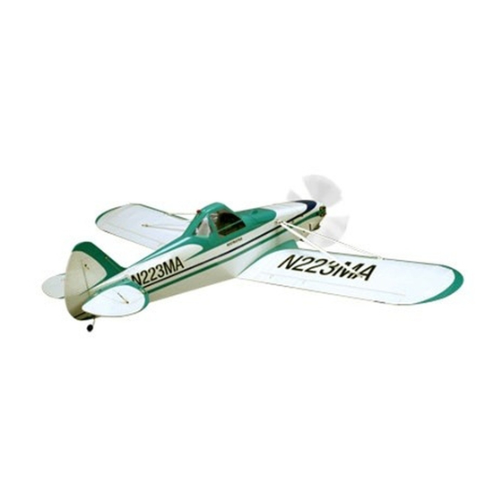
Piper Pawnee 40 ARF
Specifications
Wingspan ........................................80 in (2032mm)
Wing Area ..........................942 sq in (60.77 sq dm)
Length .......................................55.8 in (1417.3mm)
Weight .......................................... 8–9 lb (3.6–4 kg)
www.modellmarkt24.ch
www.modellmarkt24.ch
ASSEMBLY MANUAL
Engine ..................................... .56–.82 Four-Stroke
....................................... .40–.52 Two-Stroke
...........................................Power 46 Electric
Radio..............5-Channel w/7 Servos (6 for electric)
Advertisement
Table of Contents

Related Manuals for Hangar 9 Piper Pawnee 40 ARF


Summary of Contents for Hangar 9 Piper Pawnee 40 ARF
- Page 1 Piper Pawnee 40 ARF ASSEMBLY MANUAL Specifications Wingspan ........80 in (2032mm) Engine ........56–.82 Four-Stroke Wing Area ......942 sq in (60.77 sq dm) ........40–.52 Two-Stroke Length ........55.8 in (1417.3mm) ...........Power 46 Electric Weight .......... 8–9 lb (3.6–4 kg) Radio....5-Channel w/7 Servos (6 for electric) www.modellmarkt24.ch...
-
Page 2: Table Of Contents
Table of Contents Using the Manual ..............3 Required Tools and Adhesives . -
Page 3: Using The Manual
Using the Manual This manual is divided into sections to help make assembly easier to understand, and to provide breaks between each major section. In addition, check boxes have been placed next to each step to keep track of each step completed. Steps with a single box ( ) are performed once, while steps with two boxes ( ) indicate that the step will require... -
Page 4: Radio And Power Systems Requirements
Radio and Power Systems Requirements • 5-channel radio system (minimum) w/receiver • Large Servo Arm (JSP98060) (for use on flap servos) • 700mAh Ni-Cd 4-cell (JSP91010) • JR Standard Switch (JSP98010) or JR Chargeswitch (JRPA004) • DS821 Digital Sport Servo (JRPS821) (7) or equivalent (6 when building electric version) Recommended Servo Extensions 5-channel Radio System Aileron... -
Page 5: Recommended Setup-2-Stroke Glow
Recommended Setup–2-Stroke Glow • Evolution .52NX with Muffler (EVOE0520) ® • Evolution Propeller 11 x 5 (EVO11050) to 11 x 6 (EVO11060) Evolution .52NX EVOE0520 Recommended Setup–4-Stroke Glow • Saito ™ .82 AAC w/Muffler (SAIE082A or SAIE082AGK) • Evolution Propeller 13 x 8 (EVO13080) or 14 x 6 (EVO14060) Saito .82 AAC SAIE082A Recommended Setup–Electric... -
Page 6: Warranty Period
Warranty Period Exclusive Warranty- Horizon Hobby, Inc., (Horizon) warranties that the Products purchased (the "Product") will be free from defects in materials and workmanship at the date of purchase by the Purchaser. Limited Warranty (a) This warranty is limited to the original Purchaser ("Purchaser") and is not transferable. REPAIR OR REPLACEMENT AS PROVIDED UNDER THIS WARRANTY IS THE EXCLUSIVE REMEDY OF THE PURCHASER. -
Page 7: Questions, Assistance, And Repairs
Questions, Assistance, and Repairs Your local hobby store and/or place of purchase cannot provide warranty support or repair. Once assembly, setup or use of the Product has been started, you must contact Horizon directly. This will enable Horizon to better answer your questions and service you in the event that you may need any assistance. -
Page 8: Safety, Precautions, And Warnings
Safety, Precautions, and Warnings This model is controlled by a radio signal that is subject to interference from many sources outside your control. This interference can cause momentary loss of control so it is advisable to always keep a safe distance in all directions around your model, as this margin will help to avoid collisions or injury. -
Page 9: Contents Of Kit
Contents of Kit Large Replacement Parts A. HAN4031 Fuselage w/Hatch B. HAN4032 Right Wing C. HAN4033 Left Wing D. HAN4034 Horizontal Stab and Elevator E. HAN4035 Wing Struts F. HAN4036 Rudder G. HAN4037 Landing Gear H. HAN4038 Wheels I. HAN4039 Cowl J. -
Page 10: Section 1: Landing Gear And Rudder Installation
Section 1: Landing Gear and Rudder Installation o Required Parts Step 3 • Wheel assembly (2) • Landing gear Slide the inner wheel hub onto the landing gear. The wheel • Landing gear strap (4) • Tail gear assembly collar is then installed by tightening the setscrew onto the •... - Page 11 Section 1: Landing Gear and Rudder Installation o o Step 5 Step 6 Slide the outer wheel hub back into the wheel. Slide the Reinstall the four sheet metal screws to secure the inner supplied hex wrench into the screw hole in the outer and outer wheel hubs in the wheel.
- Page 12 Section 1: Landing Gear and Rudder Installation Step 9 Step 11 Attach the landing gear to the fuselage using four landing Apply a small amount of petroleum jelly to the top and gear straps and eight 3mm x 10mm sheet metal screws bottom of the tail gear bushing.
- Page 13 Section 1: Landing Gear and Rudder Installation Step 13 Step 15 Use a pin drill and 1/16-inch (1.5mm) drill bit to drill Slide each of the hinges into the rudder until the T-pin is a hole in the center of each hinge slot in the fin and resting on the hinge line of the rudder.
- Page 14 Section 1: Landing Gear and Rudder Installation Step 17 Step 19 As you slide the rudder onto the tail gear wire, slide the Remove the T-pins from the hinges. Apply thin CA to hinges for the rudder into the slots in the fin. The rudder both sides of the three hinges.
- Page 15 Section 1: Landing Gear and Rudder Installation Step 21 Step 22 Move the rudder right and left a number of times to Secure the tail wheel using two 1/16-inch wheel collars condition the hinges. and two setscrews. Tighten the setscrews using the supplied hex wrench.
-
Page 16: Section 2: Aileron And Flap Servo Installation
Section 2: Aileron and Flap Servo Installation ooo Required Parts Step 2 • Snap link (4) • Nylon clevis (4) Position the servo onto the servo cover. The servo horn • Clevis retainer (4) will be centered and in line with the outer edge of the •... - Page 17 Section 2: Aileron and Flap Servo Installation ooo ooo Step 4 Step 6 Lightly sand the servo mounting blocks on the edge where Transfer the locations for the servo mounting screws onto they will be glued to the servo cover. This will allow the the servo mounting blocks using a pencil.
- Page 18 Section 2: Aileron and Flap Servo Installation ooo Step 8 Step 10a (aileron servos only) Apply 2–3 drops of thin CA into each of the holes to Remove the supplied servo arm from the aileron servo. harden the surrounding wood. This will make the screws After centering the servo, attach a standard double arm more secure and prevent them from vibrating loose.
- Page 19 Section 2: Aileron and Flap Servo Installation ooo ooo Step 11 Step 13 Pass the servo extension through the wing and into the Use a pin drill and 5/64-inch (2mm) drill bit to enlarge bay for the flap servo. Use four #2 x 3/8-inch sheet metal the outermost hole in the servo arm to accept the screws to attach the servo cover to the wing.
- Page 20 Section 2: Aileron and Flap Servo Installation ooo ooo Step 15 Step 17 Secure the pushrod wire using one of the snap links Turn on the radio system and plug the aileron servo into provided with your Piper Pawnee 40. the receiver.
-
Page 21: Section 3: Wing Attachment
Section 3: Wing Attachment Required Parts Step 2 • Wing strut (front) (right and left) Thread a strut end onto each of the struts. • Wing strut (rear) (right and left) • 3mm nut (4) • Strut end (4) •... - Page 22 Section 3: Wing Attachment o Step 4 Step 6 Attach the fuselage strut brackets using four Slide the wing tubes into the fuselage. Guide the servo 4-40 x 1/2-inch socket head screws and four #4 washers. leads for the aileron and flap servos into the opening in The bracket will angle down and point toward the wing the fuselage while positioning the wing.
- Page 23 Section 3: Wing Attachment o o Step 8 Step 10 Attach the wing struts to the wing strut brackets using Align the holes at the ends of the struts with the holes 4-40 x 1/2-inch socket head screws and 4-40 lock nuts. in the fuselage bracket.
- Page 24 Section 3: Wing Attachment o o Step 11 Step 12 Attach the struts to the fuselage strut brackets using two Once the length of the struts has been set, make sure to strut attachment pins and two retainer pin clips. use threadlock on the nuts and strut ends to prevent them from vibrating loose.
-
Page 25: Section 4: Stabilizer/Elevator Installation
Section 4: Stabilizer/Elevator Installation Required Parts Step 2 • Stabilizer/elevator (right and left) Attach one half of the stabilizer using two 4-40 x 1/2-inch • 4-40 x 1/2-inch socket head screws (10) socket head screws and two #4 washers. Leave the screws •... - Page 26 Section 4: Stabilizer/Elevator Installation Step 4 Step 6 Attach the tail rigging with the long and medium tabs to Attach the tabs to the top and bottom of the stabilizer the bottom of the fuselage using two #2 x 1/2-inch sheet using four 4-40 x 1/2-inch socket head screws and four metal screws.
- Page 27 Section 4: Stabilizer/Elevator Installation Step 7 Step 9 Connect the rigging to the tabs on the stabilizer. Once all the cables have been attached, go back and tighten the bolts holding the tabs at the stabilizer. Do not crush the wood of the stabilizer by over-tightening the screws.
-
Page 28: Section 5: Radio Installation
Section 5: Radio Installation o Required Parts Step 2 • Fuselage assembly • Servo w/hardware (2) Drill four holes for the servo mounting screws using a • Receiver • Receiver battery pin drill and 1/16-inch (1.5mm) drill bit. • Switch harness •... - Page 29 Section 5: Radio Installation o Step 4 Step 6 Use the screws supplied with the servo and a #1 Phillips Wrap the receiver battery in foam and secure it to the screwdriver to secure the servo to the radio tray. radio tray using the supplied hook and loop strap.
- Page 30 Section 5: Radio Installation o o Step 8 Step 10 Slide the 32 -inch (825mm) pushrod into the pushrod Secure the pushrod wire using one of the snap links tube for the rudder. It is easiest to start by inserting the provided with your Piper Pawnee 40.
- Page 31 Section 5: Radio Installation Step 12 Step 14 Slide the two 5/32-inch wheel collars onto the 32-inch Thread a clevis on the remaining 31 -inch (794mm) (813mm) elevator pushrod. Secure the collars near the pushrod. Slide the pushrod into the pushrod tube from bend using a 3mm x 8mm machine screw and #2 Phillips outside the fuselage and attach the clevis to the center screwdriver.
-
Page 32: Section 6: 2-Stroke Engine Installation
Section 6: 2-Stroke Engine Installation Required Parts Step 2 • Engine mount • 8-32 lock nut (4) Temporarily install the rear 8-32 x 1-inch machine screws • Clevis • Clevis retainer and 8-32 lock nuts to attach the mounting plates to the •... - Page 33 Section 6: 2-Stroke Engine Installation Step 4 Step 6 Use a pencil to mark the location of the throttle pushrod Roughen the outside of the 11 -inch (300mm) throttle tube on the firewall. pushrod tube using sandpaper. Slide the tube into the hole, leaving around 1-inch (25mm) of the tube forward of the firewall.
- Page 34 Section 6: 2-Stroke Engine Installation Step 8 Step 10 Slide a clevis retainer onto a clevis, then thread the clevis Attach the muffler to your engine following the instructions onto the 17 -inch (450mm) throttle pushrod. provided with your particular engine. ...
- Page 35 Section 6: 2-Stroke Engine Installation Step 12 Step 14 Slide the tank into the fuselage, making sure the vent Connect the lines from the fuel tank to the engine and line faces toward the top of the fuselage. muffler.
-
Page 36: Section 7: 4-Stroke Installation
Section 7: 4-Stroke Installation Required Parts Step 2 • Engine mount • 8-32 lock nut (4) Temporarily install the rear 8-32 x 1-inch machine screws • Engine mount plate (2) • Fuel tank and 8-32 lock nuts to attach the mounting plates to the •... - Page 37 Section 7: 4-Stroke Installation Step 4 Step 6 Slide the engine between the mount and mounting plates. Remove the engine from the engine mount. Use a drill Install the remaining 8-32 x 1-inch machine screws and and 11/64-inch (4.5mm) drill bit to drill the hole for the 8-32 lock nuts at the front of the mounting plates.
- Page 38 Section 7: 4-Stroke Installation Step 8 Step 10 Attach the Z-bend to the carburetor by inserting the Use side cutters to trim the pushrod tube as shown. Z-bend in the outer hole of the carburetor arm as shown. ...
- Page 39 Section 7: 4-Stroke Installation Step 12 Step 14 Attach the muffler to your engine following the instructions Slide the tank into the fuselage, making sure the vent line provided with your particular engine. faces toward the top of the fuselage. ...
- Page 40 Section 7: 4-Stroke Installation Step 16 Connect the lines from the fuel tank to the engine and muffler. We used a fuel dot to allow fueling the tank from outside the cowling. www.modellmarkt24.ch www.modellmarkt24.ch...
-
Page 41: Section 8: Throttle Servo Installation
Section 8: Throttle Servo Installation Required Parts Step 3 • Fuselage assembly • Servo Use a felt-tipped pen to mark the pushrod where it crosses • Snap link the outer hole on the servo horn. • Plywood pushrod standoff Required Tools and Adhesives •... - Page 42 Section 8: Throttle Servo Installation Step 5 Step 7 Use a pin drill and a 5/64-inch (2mm) drill bit to Slide the plywood pushrod standoff so it can be glued to enlarge the outer hole in the servo arm. Slide the the side of the fuselage using medium CA as shown.
-
Page 43: Section 9: Electric Motor Installation
Section 9: Electric Motor Installation Required Parts Step 2 • Fuselage assembly • Motor w/hardware Use a hobby knife and a covering iron to open the cooling • Electronic speed control • Hook and loop strap air exit in the bottom of the fuselage. Cutting the covering •... - Page 44 Section 9: Electric Motor Installation Step 4 Step 6 Attach the X-mount to the motor using the screws Secure the speed controller to the bottom of the fuselage provided with the motor. using hook and loop tape as shown. Secure the wires between the motor and speed control so they do not interfere with the operation of the motor.
-
Page 45: Section 10: Cowling And Canopy Installation
Section 10: Cowling and Canopy Installation Required Parts Step 2 • Fuselage assembly • Cowling Secure the cowling to the fuselage using the screws • 1/4-inch (4mm) tubing (4) • #4 washer (4) prepared in the previous step. • Spinner w/hardware •... - Page 46 Section 10: Cowling and Canopy Installation Step 4 Step 5 Use the following images as a guide for cutting the Use the following images as a guide for cutting the cowling for a 4-stroke engine. Make sure to make cutouts cowling for a 2-stroke engine.
-
Page 47: Section 11: Recommended Center Of Gravity (Cg)
Section 10: Cowling and Canopy Installation Step 6 Step 7 Use medium CA to glue the pilot seat in the cockpit. Note Use canopy glue to secure the canopy to the fuselage. Use that the seat does fit slightly forward of the rear of the low-tack tape to hold the canopy in position until the glue cockpit as shown. -
Page 48: Section 12: Control Throws
Section 12: Control Throws The amount of control throw should be adjusted as closely Flap (Mid Position) as possible using mechanical means, rather than making 7/8-inch down large changes electronically at the radio. By moving 22mm down the position of the clevis at the control horn toward the 25 degrees down outermost hole, you will decrease the amount of control Flap (Full Flap) -
Page 49: Section 13: Pre-Flight
Section 13: Pre-Flight Charge both the transmitter and receiver pack for your Check all the control horns, servo horns and clevises to airplane. Use the recommended charger supplied with make sure they are secure and in good condition. Replace your particular radio system, following the instructions any items that would be considered questionable. -
Page 50: 2008 Official Ama National Model Aircraft Safety Code
2008 Official AMA National Model Aircraft Safety Code GENERAL 8. I will not operate model aircraft carrying pyrotechnic devices which explode burn, or propel a projectile 1. A model aircraft shall be defined as a non-human- of any kind. Exceptions include Free Flight fuses or carrying device capable of sustained flight in the devices that burn producing smoke and are securely atmosphere. -
Page 51: National Model Aircraft Safety Code
2008 Official AMA National Model Aircraft Safety Code Radio Control 7. With the exception of events flown under official AMA rules, no powered model may be flown outdoors closer 1. All model flying shall be conducted in a manner to than 25 feet to any individual, except for the pilot and avoid over flight of unprotected people. - Page 52 © 2008 Horizon Hobby, Inc. 4105 Fieldstone Road Champaign, Illinois 61822 (877) 504-0233 horizonhobby.com 12402 www.modellmarkt24.ch www.modellmarkt24.ch...
Need help?
Do you have a question about the Piper Pawnee 40 ARF and is the answer not in the manual?
Questions and answers