
Subscribe to Our Youtube Channel
Related Manuals for Phoenix Model Extra 300 S


Summary of Contents for Phoenix Model Extra 300 S
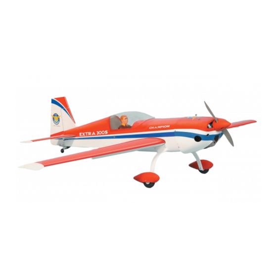
- Page 1 I n s t r u c t i o n M a n u a l Wingspan : 1900 mm (74.8 inch) Length 1720 mm (67.7 inch) Weight : 5100g - 5600g Engine : 160 two stroke Radio : 6 channel/ 5 high torque servo standard servo...
-
Page 2: Kit Contents
Instruction Manual YAK 54 KIT CONTENTS: We have organized the parts as they come out of the box for better identification during assembly. We recommend that you regroup the parts in the same manner. This will ensure you have all of parts required before you begin assembly. KIT CONTENTS MAIN GEAR ASSEMBLY RUDDER CONTROL SYSTEM... -
Page 3: Tools And Supplies Needed
Instruction Manual EXTRA 300S • Do not start the engine if people are near. Do not TOOLS AND SUPPLIES NEEDED stand in line with the side of the propeller. • Make engine adjustments from behind the propeller • 2 bender plier •... - Page 4 Instruction Manual EXTRA 300S 4. Test fit the ailerons to the wing with the hinges. If the hinges don’t remain centered, stick a pin through the middle of the hinge to hold it in position. TEMPORARY PIN TO KEEP HINGE CENTERED Remove the covering...
-
Page 5: Installing The Control Horns
Instruction Manual EXTRA 300S 6. Temporarily position the aileron servo into the 2. Drill through the mark you made with a (3mm) servo bay. Drill a 1.6mm hole through the four drill bit. Hard the hole with thin CA. Install the mounting holes of the servo, drilling through the control horn. -
Page 6: Installing The Horizontal Stabilizer
Instruction Manual EXTRA 300S 2. Make the same way for the plastic linkball to the INSTALLING THE HORIZONTAL STABILIZER other side of the pushrod wire. 1. Using a modeling knife, cut away the covering from the fuselage for the stabilizer and remove it. Adjust the linkages 3. -
Page 7: Installing The Rudder
Instruction Manual EXTRA 300S 5. Remove the stabilizer. Using the lines you just mounting platform sides in the fuselage. Insert drew as a guide, carefully remove the covering the stabilizer in place and re-align. Double from between them using a modeling knife. check all of your measurements one more time before the epoxy cures. -
Page 8: Installing The Tail Wheel
Instruction Manual EXTRA 300S 2. Set the tail wheel assembly in place on the plywood plate. 3. Drill 2,6mm pilot holes through the plywood plate. 4. Secure the tail wheel bracket in place using two 3mm x 12mm screw. 5. Align the tail wheel wire so that the wire is parallel with the bottom of the rudder. -
Page 9: Installing The Wheel Pants
Instruction Manual EXTRA 300S 16 mm flat washer INSTALLING THE WHEEL PANTS 1. Locate the wheel pants from the hardware bag. Mark the locations of the mounting axles onto the wheel pants. The locations of the two mounting holes are the middle of the wheel opening, on right side, left side and 10mm from the bottom of the wheel pant. -
Page 10: Installing The Engine
Instruction Manual EXTRA 300S 3. Carefully bend the second nylon tube up at a 45 INSTALLING THE ENGINE degree angle (using a cigarette lighter). This This manual, we used the OS 160 - two stroke tube will be the vent tube to the muffler. 1. -
Page 11: Installing The Throttle Servo
Instruction Manual EXTRA 300S CA glue 3. The elevator has a block wood plate for mounting the control horn. One elevator control INSTALLING THE THROTTLE SERVO horn in positioned on each elevator. Using a ruler and a pen, locate and mark the location of 1. -
Page 12: Installing The Rudder Linkages
Instruction Manual EXTRA 300S The elevator linkages are assembled as shown below 3. The control horn should be mounted on the right side of the rudder at the leading edge, in line with the rudder pushrod. 22mm 22mm 95mm Control horn INSTALLING THE RUDDER LINKAGES Repeat these step as installing the aileron linkages (Page 4 and page 5). -
Page 13: Installing The Throttle
Instruction Manual EXTRA 300S INSTALLING THE THROTTLE opening. Hold the cowl firmly in place using several pieces of masking tape. 1. Install one adjustable metal connector through the third hole out from the center of one servo arm, 4. While holding the cowl firmly in position, drill enlarge the hole in the servo arm using a 2mm drill four 1,6mm pilot holes through both the cowl bit to accommodate the servo connector. -
Page 14: Installing The Switch
Instruction Manual EXTRA 300S INSTALLING THE SWITCH INSTALLING and secure the wing 1. Glue the plastic part to the wing joiner. 1. The switch should be mounted on the fuselage side, opposite the muffler, close enough to the receiver so the lead will reach. Use the face plate of the switch cut out and locate the mounting holes. -
Page 15: Control Throws
Instruction Manual EXTRA 300S BALANCING CONTROL THROWS 1. It is critical that your airplane be balanced 1. We highly recommend setting up a plane using correctly. Improper balance will cause your the control throws listed. plane to lose control and crash. 2. - Page 16 I/C FLIGHT WARNINGS Always operate in open areas, away Keep all onlookers (especially small from factories, hospitals, schools, THE PROPELLER IS DANGEROUS children and animals) well back from buildings and houses etc. NEVER fly Keep fingers, clothing (ties, shirt the area of operation. This is a flying your aircraft close to people or built sleeves, scarves) or any other loose aircraft, which will cause serious...
- Page 17 I/C FLIGHT GUIDELINES Operate the control sticks on the When ready to fly, first extend the transmitter and check that the control transmitter aerial. surfaces move freely and in the ALWAYS land the model INTO the CORRECT directions. wind, this ensures that the model lands at the slowest possible speed.
Need help?
Do you have a question about the Extra 300 S and is the answer not in the manual?
Questions and answers