Table of Contents
Advertisement
Quick Links
Download this manual
See also:
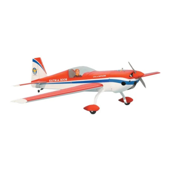
Instruction Manual
SPECIFICATION
- Wingspan: 1472mm (57.9 in)
- Length: 1335mm (52.5 in)
- Flying weight: 2800-3000 gr
- Wing area: 38.5 dm2
- Wing loading: 76g/dm2
- Wing type: Naca airfoils
- Covering type: Genuine ORACOVER®
- Gear type: Aluminum Hi-grade for main gear
and spring wire for tail gear (included)
- Spinner size: Plastic 58mm (included)
- Radio: 4 channel minimum (not included)
- Servo: 5 standard servo: 2 aileron; 1 elevator;
1 rudder; 1 throttle (not included)
- Recommended receiver battery:
4.8-6V / 800-1200mAh NiMH (not included)
- Servo mount: 21mm x 42 mm
- Propeller: suit with your engine
Instruction Manual
- Engine: .46-.55 / 2-stroke or .52/4-stroke
glow engine (not included)
- Motor: brushless outrunner 1000-1400 W,
480 KV (not included)
- Gravity CG: 85-90 mm (3.3-3.5 in) Back from
the leading edge of the wing, at the fuselage
- Control throw Ailerons: Low: 8mm up/down,
10% expo; High: 10mm up/down, 10% expo
- Control throw Elevators: Low: 8mm up/down,
12% expo; High: 10mm up/down, 12% expo
- Control throw Rudder: Low: 25mm right/left,
15% expo; High: 40mm right/left, 15% expo
- Experience level: Intermediate
- Plane type: Scale Aerobatic
RECOMMENDED MOTOR AND BATTERY SET UP
- Motor: RIMFIRE .46-.55 (not included)
- Lipo cell: 6 cells / 4000 – 5500mAh (not included)
- Esc: 50-80A (not included)
Advertisement
Table of Contents

Subscribe to Our Youtube Channel
Related Manuals for Phoenix Model Extra 300S


Summary of Contents for Phoenix Model Extra 300S
-
Page 1: Instruction Manual
Instruction Manual SPECIFICATION - Engine: .46-.55 / 2-stroke or .52/4-stroke - Wingspan: 1472mm (57.9 in) glow engine (not included) - Length: 1335mm (52.5 in) - Motor: brushless outrunner 1000-1400 W, - Flying weight: 2800-3000 gr 480 KV (not included) - Wing area: 38.5 dm2 - Gravity CG: 85-90 mm (3.3-3.5 in) Back from - Wing loading: 76g/dm2 the leading edge of the wing, at the fuselage... -
Page 2: Tools And Supplies Needed
This will assure proper assembly. The TEMPORARY PIN EXTRA 300S .46-.55 SCALE 1:5 ARF is hand made TO KEEP HINGE from natural materials, every plane is unique and minor adjustments may have to be made. -
Page 3: Installing The Aileron Servos
INSTALLING THE AILERON SERVOS 5. Place the aileron servo tray / hatch into the servo box on the bottom of the wing and drill 1. Install the rubber grommets and brass eyelets 1,6mm pilot holes through the tray and the onto the aileron servo. -
Page 4: Installing The Aileron Linkages
3. Repeat step # 1 - # 2 to install the control horn on the opposite aileron. RIGHT WRONG INSTALLING THE AILERON LINKAGES 8. Insert the 90 degree bend down through the 1. Working with the aileron linkage for now, thread hole in the servo arm. -
Page 5: Vertical Stabilizer Installation
Plastic screw 6. After the epoxy has fully cured, remove the 3. Attach the wing to the fuselage as picture. masking tape or T-pins used to hold the stabilizer in place and carefully inspect the glue 4. Test the position of the elevator and adjust it as joints. - Page 6 paper towel and rubbing alcohol and hold the stabilizer in place with T-pins or masking tape. Allow the epoxy to fully cure before proceeding. Glue with epoxy 3. Now, remove the vertical stabilizer and using a modeling knife, carefully cut just inside the marked lines and remove the film on both sides of the vertical stabilizer.
-
Page 7: Assemble And Install The Landing Gear
assemble and install the landing gear 1. Slide a landing gear fairing onto each landing gear leg as shown. Hold the gear legs up to the fuselage in position to confirm that you have the fairings on correctly before continuing. Fairing 16mm flat washer 2. -
Page 8: Installing The Engine
ENGINE INSTALLATION INSTALLING THE THROTTLE PUSHROD HOUSING 1. Install the engine mount into the fire wall using 16mm 4mm x 20mm screw. 2. Place the engine into the engine mount and align it properly with the front of the cowling. The distance from the firewall to the front of the 60mm engine thrust washer should 110mm. -
Page 9: Installing The Stopper Assembly
5. Test fit the stopper assembly into the tank. It may be necessary to remove some of the flashing around the tank opening using a Battery modeling knife. If flashing is present, make sure none of it falls into the tank. 6. -
Page 10: Installing The Elevator Pushrod
To carburator To muffler Control horn elevator To vent Tube SERVO INSTALLATION INSTALLING THE FUSELAGE SERVOS 1. Install the rubber grommets and brass collets into the elevator, rudder and throttle servos. Test fit the servos into the servo tray. Trim the tray if necessary to fit your servos 2. -
Page 11: Installing The Rudder Pushrod
7. Attach clevis to the third hole in the control horn. Install a silicone tube on the clevis. 8. Locate one nylon servo arm, and using wire cutters, remove all but one of the arms using a 2mm drill bit, enlarge the third hole out from the center to accommodate the rudder pushrod wire. -
Page 12: Installing The Throttle
INSTALLING THE THROTTLE 3. Slide the cowl back into place. Align the front of the cowl with the crankshaft of the engine. The 1. Install one adjustable metal connector through front of the cowl should be positioned so the the third hole out from the center of one servo crankshaft is in the middle of the precut arm, enlarge the hole in the servo arm using a opening. -
Page 13: Open And Close The Canopy
FINAL ASSEMBLY OPEN AND CLOSE THE CANOPY INSTALLING THE SPINNER Install the spinner back-plate, propeller and spinner cone. The spinner cone is held in place using two 3mm x 15mm wood screws. The propeller should not touch any part of the spinner cone. - Page 14 LATERAL BALANCE After you have balanced a plane on the C.G. You should laterally balance it. Doing this will help the airplane track straighter. 5. Turn the airplane upside down. Attach one loop of heavy string to the engine crankshaft and one to the tail wheel wire.
-
Page 15: Metric Conversions
I/C FLIGHT WARNINGS Metric Conversions Inches x 25.4 = mm (conversion factor) 1/64" .4 mm 3/16" 4.8 mm 1" 25.4 mm 21" = 533.4 mm 1/32" .8 mm 1/4" 6.4 mm 2" = 50.8 mm 24" = 609.6 mm 1/16" 1.6 mm 3/8"... - Page 16 I/C FLIGHT GUIDELINES 2-View Drawing Use this two- view drawing to design your trim scheme for your Extra 300S Made in Vietnam...
Need help?
Do you have a question about the Extra 300S and is the answer not in the manual?
Questions and answers
Hi what's the height of firewall until the top of ?