Table of Contents
Advertisement
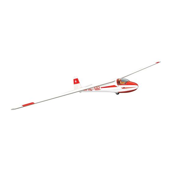
SPECIFICATION
- Wingspan: 6000mm (236.2 in)
- Length: 2873mm (113.1 in)
- Flying weight: 14-18 kg
- Wing area: 219.4 dm2
- Wing loading: 64g/dm2
- Wing type: HQ airfoils
- Covering type: Genuine ORACOVER®
- Radio: 6 channel minimum (not included)
- Servo: 6 standard hi-torque servo: 2 aileron;
2 elevator; 1 rudder (not included)
- Recommended receiver battery:
6.0V 2400/2600mAh NiMH (2) (not included)
- Servo mount: 21mm x 42 mm
- Flap: 2 electric flaps 440mm (not included)
- Propeller: suit with your engine
- Motor: brushless outrunner 2600-3000 W,
149 KV (not included)
Instruction Manual
- Gravity CG: 150 mm (5.9 in) Back from the
leading edge of the wing, at the fuselage
- Control throw Ailerons: Low: 15mm up/down,
10% expo; High: 20mm up/down, 10% expo
- Control throw Elevators: Low: 15mm up/down,
12% expo; High: 20mm up/down, 12% expo
- Control throw Rudder: Low: 45mm right/left,
15% expo; High: 70mm right/left, 15% expo
- Experience level: Intermediate
- Plane type: Giant Scale Sailplane
RECOMMENDED MOTOR AND BATTERY SET UP
- Motor: hacker brushless a60-18l kv149 (not included)
- Propeller: hacker 20x13 foilding (not included)
- Lipo cell: 12 cells / 5000 – 6000mAh (not included)
- Esc: 120-160A / HV (not included)
Advertisement
Table of Contents

Related Manuals for Phoenix Model Ka-8b ELECTRIC 6000


Summary of Contents for Phoenix Model Ka-8b ELECTRIC 6000
-
Page 1: Instruction Manual
Instruction Manual SPECIFICATION - Wingspan: 6000mm (236.2 in) - Gravity CG: 150 mm (5.9 in) Back from the - Length: 2873mm (113.1 in) leading edge of the wing, at the fuselage - Flying weight: 14-18 kg - Control throw Ailerons: Low: 15mm up/down, - Wing area: 219.4 dm2 10% expo;... -
Page 2: Tools And Supplies Needed
This will assure proper assembly. The TEMPORARY PIN Ka-8b ELECTRIC 6000 ARF 1/2.5 SCALE is hand TO KEEP HINGE made from natural materials, every plane is unique CENTERED and minor adjustments may have to be made. -
Page 3: Installing The Aileron Servos
Instruction Manual INSTALLING THE AILERON SERVOS 5. Place the aileron servo tray / hatch into the servo box on the bottom of the wing and drill 1. Install the rubber grommets and brass eyelets 1,6mm pilot holes through the tray and the onto the aileron servo. -
Page 4: Installing The Aileron Linkages
Instruction Manual 2. Repeat step # 1 - # 2 to install the control horn on the opposite aileron. INSTALLING THE AILERON LINKAGES The aileron linkages are assembled as shown below. 22mm 22mm 90mm Screw Flat washer Aluminum link ball Plastic link ball Servo arm Flat washer... - Page 5 Instruction Manual 2. Install the air brake into the bay. 3. Secure the screw. Screw here WING TIP INSTALLING THE elevator servos Remove the covering. WING TIP joining the wing halves Remove the covering 1. Slide two carbon tube the wing. Carbon dihedral brace 2.
-
Page 6: Installing The Horizontal Stabilizer
Instruction Manual INSTALLING THE HORIZONTAL STABILIZER 1. Remove the covering. Control horn Remove the covering elevator INSTALLING THE ELEVATOR LINKAGES The elevator linkages are assembled as shown below 22mm 22mm 110mm 2. Secure the horizontal onto the fuselage. Repeat these step as installing the aileron linkages. -
Page 7: Installing The Rudder
Instruction Manual INSTALLING THE RUDDER 1. Repeat step #1 - #2 from installing the aileron to install the rudder. 5. Secure the vertical stabilizer into the fuselage. 2. Remove the covering from the fuselage. 3. Insert the vertical stabilizer into the fuselage. INSTALLING THE rudder SERVOS Repeat these step from installing the aileron linkages to install the rudder linkages. -
Page 8: Installing The Wing
Instruction Manual 3. Glue the wooden plate to the fuselage. 22mm 22mm 185mm C.A Glue 4. Attach the fuselage to the fuselage. Dihedral brace INSTALLING THE main landing gear 1. The full set wheel. Screw INSTALLING THE WING 2. Secure the collars. 1. -
Page 9: Installing The Receiver And Battery
Instruction Manual 2. Secure the wing with 6 nylon screw. Glue the plastic cover to the fuselage. C.A Glue 3. Secure the wing. Glue the plastic cover to the fuselage. C.A Glue Screw INSTALLING THE RECEIVER AND BATTERY installing the towing line 1. -
Page 10: Installing The Motor
Instruction Manual - Secure the engine mount. Screw Remove the covering for axles and for the air cooling the esc and motor. INSTALLING THE MOTOR - In this case, your plane can fly by themself - Do not need towed by another plane. SET UP ELECTRIC SYSTEM RECOMMANDED Motor : Hacker A60-18L KV149... -
Page 11: Control Throws
Instruction Manual BALANCING 1. It is critical that your airplane be balanced correctly. Improper balance will cause your plane to lose control and crash. CONTROL THROWS THE CENTER OF GRAVITY IS LOCATED 1. We highly recommend setting up a plane using 150mm BACK FROM THE LEADING EDGE the control throws listed. - Page 12 I/C FLIGHT GUIDELINES Operate the control sticks on the When ready to fly, first extend the transmitter and check that the control transmitter aerial. surfaces move freely and in the ALWAYS land the model INTO the CORRECT directions. wind, this ensures that the model lands at the slowest possible speed.
Need help?
Do you have a question about the Ka-8b ELECTRIC 6000 and is the answer not in the manual?
Questions and answers