
Related Manuals for Phoenix Model EXTRA 300S


Summary of Contents for Phoenix Model EXTRA 300S
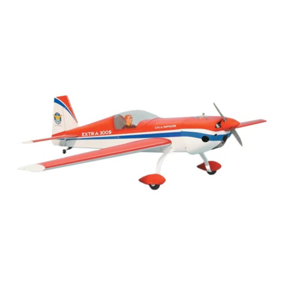
- Page 1 I n s t r u c t i o n M a n u a l Wingspan : mm (74.21 inch) 1885 Length mm (66.14 inch) 1680 Weight : 5000gr - 5400gr Engine : 160 two stroke / 33cc DLE Gas Radio : 6 channel/ 5 high torque servo standard servo...
-
Page 3: Kit Contents
Instruction Manual EXTRA 300S KIT CONTENTS: We have organized the parts as they come out of the box for better identification during assembly. We recommend that you regroup the parts in the same manner. This will ensure you have all of parts required before you begin assembly. -
Page 4: Safety Precaution
1. Please trial fit all the parts. Make sure you have the correct parts and that they fit and are aligned properly before gluing! This will assure proper assembly. The EXTRA 300S is hand made from INSTALLING THE AILERONS natural materials, every plane is unique and minor adjustments may have to be made. -
Page 5: Installing The Control Horns
Instruction Manual EXTRA 300S INSTALL THE AILERONS SERVOS & PUSHRODS 1. Install the servo in the wing require the use of one 305mm servo extension for each aileron servo. One Y-harness connector is required and is used to allow the aileron servo to plug into one slot in your receiver. -
Page 6: Installing The Aileron Linkages
Instruction Manual EXTRA 300S 2. Secure the control horn into the aileron. 1. Locate the pushrod wire. Slide a silicon clevis retainer onto a clevis. Screw a M3 nut and a threaded metal clevis onto the threaded end of the wire. Tighten the nut against the clevis and... -
Page 7: Installing The Horizontal Stabilizer
Instruction Manual EXTRA 300S 2. Remove the covering from the stabilizer. When cutting through the covering to remove it, cut with only enough pressure to only cut through the covering it's self. Cutting into the balsa structure may weaken it. This could lead to possible failure during flight. -
Page 8: Installing The Rudder
Instruction Manual EXTRA 300S INSTALLING THE RUDDER 5. When you are sure that everything is aligned correctly, mix up a generous amount of 30 minute epoxy. Apply a thin layer to the bottom Repeat step 1 - step 2 from the installing aileron and to the top of the stabilizer mounting area for the installing rudder. -
Page 9: Installing The Tail Wheel
Instruction Manual EXTRA 300S INSTALLING THE TAIL WHEEL 5. Connect the spring. 1. The tail wheel set. INSTALLING THE MAIN LANDING GEAR 2. Remove the covering. 1. Nuts have been installed at the factory. 2. Install main landing gear into the fuselage using (4) 4mm x 20mm socket head screws and flat washers provided in the kit. -
Page 10: Installing The Wheel Pants
Instruction Manual EXTRA 300S INSTALLING THE WHEEL PANTS 3. Now, remove the engine. Using a 5mm drill bit, drill holes through the firewall and the forward bulkhead at the marks made. 4. Slide the pushrod housing through the hole in the firewall, through the hole in the forward bulkhead, and into the servo compartment. -
Page 11: Installing The Stopper Assembly
Instruction Manual EXTRA 300S This manual, we used the DLE 30CC 7. Using a modeling knife, cut 3 lengths of fuel line 150mm long. Connect 2 lines to the 2 vent tubes and 1 line to the fuel pickup tube in the stopper. -
Page 12: Installing The Elevator Servo
Instruction Manual EXTRA 300S . Repeat these step as installing the aileron INSTALLING THE ELEVATOR SERVO linkages (Page 4 and page 5). 1. Remove the covering from both size of the fuselage. 2. Install two servo to the fuselage as shown. -
Page 13: Installing The Rudder Linkages
Instruction Manual EXTRA 300S INSTALLING THE RUDDER LINKAGES The rudder is controlled by two metal cables. Install the rudder linkages and cables as below. Aluminum ball Crimp Cable 1. Use a hobby knife to remove the covering from the openings for the rudder control cables. -
Page 14: Mounting The Cowl
Instruction Manual EXTRA 300S MOUNTING THE COWL 1. Remove the muffler and needle valve assembly from the engine. Slide the fiberglass cowl over the engine. 2. Measure and mark the locations to be cut out for engine head clearance, needle valve, muffler. -
Page 15: Final Assembly
Instruction Manual EXTRA 300S FINAL ASSEMBLY Receiver INSTALLING THE SPINNER Install the spinner back-plate, propeller and spinner cone. The spinner cone is held in place using two 3mm x 20mm wood screws. The propeller should not touch any part of the Zip tie spinner cone. -
Page 16: Lateral Balance
With the wings level, The EXTRA 300S will perform 3-D aerobatics carefully lift the airplane by the string. This may easily if you use the largest engines require two people to make it easier. - Page 17 I/C FLIGHT WARNINGS Always operate in open areas, away Keep all onlookers (especially small from factories, hospitals, schools, THE PROPELLER IS DANGEROUS children and animals) well back from buildings and houses etc. NEVER fly Keep fingers, clothing (ties, shirt the area of operation. This is a flying your aircraft close to people or built sleeves, scarves) or any other loose aircraft, which will cause serious...
- Page 18 I/C FLIGHT GUIDELINES Operate the control sticks on the When ready to fly, first extend the transmitter and check that the control transmitter aerial. surfaces move freely and in the ALWAYS land the model INTO the CORRECT directions. wind, this ensures that the model lands at the slowest possible speed.
Need help?
Do you have a question about the EXTRA 300S and is the answer not in the manual?
Questions and answers