
Related Manuals for Phoenix Model EDGE 540


Summary of Contents for Phoenix Model EDGE 540
-
Page 1: Instruction Manual
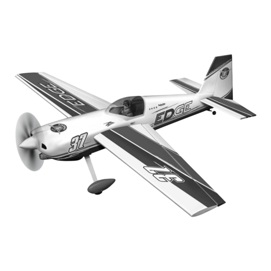
Instruction Manual Wingspan : 1400mm (55.12 in) Length : 1370mm (53.94 in) Weight : 2600gr - 2800gr Radio : 4 channel / 5 servo Engine : 46-52 / 2 stroke_52-71 / 4 stroke... -
Page 3: Kit Contents
KIT CONTENTS: We have organized the parts as they come out of the box for better identification during assembly. We recommend that you regroup the parts in the same manner. This will ensure you have all of parts required before you begin assembly. KIT CONTENTS MOTOR MOUNT ASSEMBLY MAIN GEAR ASSEMBLY... -
Page 4: Tools And Supplies Needed
This will assure proper assembly. The EDGE 540 is hand made from natural materials, every plane is unique and minor adjustments may have to be made. However, you should find the fit superior and assembly simple. -
Page 5: Installing The Aileron Linkages
7. Using pliers, carefully make a 90 degree bend down at the mark made. Cut off the excess wire, leaving about 4mm beyond the bend. Silicone Tube 8. Insert the 90 degree bend down through the hole in the servo arm. Install one nylon snap keeper over the wire to secure it to the arm. -
Page 6: Vertical Stabilizer Installation
5. Remove the stabilizer. Using the lines you just 2. Draw a center line onto the horizontal stabilizer. drew as a guide, carefully remove the covering from between them using a modeling knife. Draw a center line When cutting through the covering to remove it, cut with only enough pressure to only cut through the covering it's self. -
Page 7: Tail Wheel Installation
stabilizer mounting area. Apply epoxy to the lower rudder hinge. Set the stabilizer in place and re-align. Double check all of your Remove measurements once more before the epoxy the covering cures. Remove any excess epoxy using a paper towel and rubbing alcohol and hold the stabilizer in place with T-pins or masking tape. -
Page 8: Installing The Engine
2. Using a 5mm drill bit, carefully drill two pilot After installing the wheel pant, apply a small holes through the wheel pant at the TWO drop of thin C/A to the bottom nut. marks you made. 9. Repeat step # 1-8 to install the second wheel pant assembly. -
Page 9: Installing The Stopper Assembly
5. Test fit the stopper assembly into the tank. It may be necessary to remove some of the flashing around the tank opening using a modeling knife. If flashing is present, make sure none of it falls into the tank. 6. -
Page 10: Installing The Elevator Pushrod
SERVO INSTALLATION 10. Be sure both elevator halves are flat. Center both elevator halves and hold them in place INSTALLING THE FUSELAGE SERVOS using a couple of pieces of masking tape. 11. Connect two elevator purshord to the metal 1. Install the rubber grommets and brass collets domino connector and secure it. -
Page 11: Installing The Rudder Pushrod
INSTALLING THE RUDDER PUSHROD 1. Locate the pushrod exit slot on the left of the fuselage. 2. Carefully cut away the covering material from the slot. 3. Working from inside the fuselage, slide the threaded end of the remaining pushrod down the inside of the fuselage until the pushrod reaches the exit slot. -
Page 12: Installing The Receiver And Battery
FINAL ASSEMBLY 2. Measure and mark the locations to be cut out for engine head clearance, needle valve, INSTALLING THE SPINNER muffler. Remove the cowl and make these cutouts using a rotary tool with a cutting disc and a rotary sanding drum attachment. Install the spinner back-plate, propeller and spinner cone. -
Page 13: Control Throws
BALANCING CONTROL THROWS 1. We highly recommend setting up a plane using 1. It is critical that your airplane be balanced the control throws listed. correctly. Improper balance will cause your plane to lose control and crash. 2. The control throws should be measured at the widest point of each control surface. - Page 14 I/C FLIGHT WARNINGS Always operate in open areas, away Keep all onlookers (especially small from factories, hospitals, schools, THE PROPELLER IS DANGEROUS children and animals) well back from buildings and houses etc. NEVER fly Keep fingers, clothing (ties, shirt the area of operation. This is a flying your aircraft close to people or built sleeves, scarves) or any other loose aircraft, which will cause serious...
- Page 15 I/C FLIGHT GUIDELINES Operate the control sticks on the When ready to fly, first extend the transmitter and check that the control transmitter aerial. surfaces move freely and in the ALWAYS land the model INTO the CORRECT directions. wind, this ensures that the model lands at the slowest possible speed.
Need help?
Do you have a question about the EDGE 540 and is the answer not in the manual?
Questions and answers