
Related Manuals for AXIOMTEK SBC87842


Summary of Contents for AXIOMTEK SBC87842
- Page 1 SBC87842 ® ® Intel Atom E3827 and Celeron N2807 Processor Single Board Computer User’s Manual...
- Page 2 Axiomtek does not make any commitment to update the information in this manual. Axiomtek reserves the right to change or revise this document and/or product at any time without notice. No part of this document may be reproduced, stored in a retrieval system, or transmitted, in any form or by any means, electronic, mechanical, photocopying, recording, or otherwise, without the prior written permission of Axiomtek Co., Ltd.
-
Page 3: Esd Precautions
Wear a wrist-grounding strap, available from most electronic component stores, when handling boards and components. Trademarks Acknowledgments Axiomtek is a trademark of Axiomtek Co., Ltd. AMI is a trademark of American Megatrend Inc. IBM, PC/AT, PS/2, VGA are trademarks of International Business Machines Corporation. -
Page 4: Table Of Contents
Table of Contents Disclaimers ..................... ii ESD Precautions ................... iii Chapter 1 Introduction ..........1 Features ....................1 Specifications ..................2 Utilities Supported ................3 Chapter 2 Board and Pin Assignments ....5 Board Dimensions and Fixing Holes ..........5 Board Layout .................. - Page 5 Starting ....................27 Navigation Keys ................27 Main Menu ..................28 Advanced Menu ................. 29 Chipset Menu ..................40 Security Menu ..................42 Boot Menu ..................43 Save & Exit Menu ................45 Appendix A Watchdog Timer ........47 About Watchdog Timer ..............47 How to Use Watchdog Timer ............
- Page 6 This page is intentionally left blank.
-
Page 7: Chapter 1 Introduction
SBC87842 Single Board Computer Chapter 1 Introduction ® ® The SBC87842, a single board computer, supports Intel Atom E3827 and Celeron N2807 processors. The board delivers outstanding system performance through high-bandwidth interfaces, multiple I/O functions for interactive applications and various embedded computing solutions. -
Page 8: Specifications
SBC87842 Single Board Computer Specifications ® Intel Atom dual core E3827 1.75GHz. ® ® Intel Celeron dual core N2807 1.58GHz. Thermal Solution Passive. An optional heatspreader. Operating Temperature C~70 C~-80 C (Optional). -
Page 9: Utilities Supported
SBC87842 Single Board Computer Dimensions 143.05mm(W) x 104.65mm(D). All specifications and images are subject to change without notice. Note Utilities Supported Chipset and graphics driver Ethernet driver AHCI driver Trusted Execution Engine Sideband Fabric Device... - Page 10 SBC87842 Single Board Computer This page is intentionally left blank. Introduction...
-
Page 11: Board And Pin Assignments
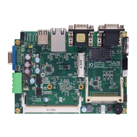
SBC87842 Single Board Computer Chapter 2 Board and Pin Assignments Board Dimensions and Fixing Holes Top View Board and Pin Assignments... - Page 12 SBC87842 Single Board Computer Bottom View Side View Board and Pin Assignments...
-
Page 13: Board Layout
SBC87842 Single Board Computer Board Layout Top View Side View Board and Pin Assignments... -
Page 14: Jumper Settings
And remove jumper clip from 2 jumper pins to open. The following illustration shows how to set up jumper. Before applying power to SBC87842, please make sure all of the jumpers are in factory default position. Below you can find a summary table of all jumpers and onboard default settings. -
Page 15: Connectors And Leds
SBC87842 Single Board Computer Connectors and LEDs Signals go to other parts of the system through connectors. Loose or improper connection might cause problems, please make sure all connectors are properly and firmly connected. Here is a summary table which shows all connectors and LEDs on the hardware. -
Page 16: Front Panel Connector (Cn1)
SBC87842 Single Board Computer 2.4.1 Front Panel Connector (CN1) Signal HDDLED+ +3.3V HDDLED- +3.3V HW RST+ HW RST- PWRSW+ PWRSW- HDD Activity LED This connection is linked to hard drive activity LED on the control panel. LED flashes when HDD is being accessed. Pin 1 and 3 connect the hard disk drive to the front panel HDD LED, pin 3 is assigned as cathode(-) and pin 1 is assigned as anode(+). -
Page 17: Full-Size Pci-Express Mini Card And Msata Connector (Cn6)
SBC87842 Single Board Computer 2.4.4 Full-size PCI-Express Mini Card and mSATA Connector (CN6) The CN6 is a full-size PCI-Express Mini Card connector applying to either PCI-Express or USB 2.0 with mSATA support. It also complies with PCI-Express Mini Card Spec. -
Page 18: Vga Connector (Cn7)
SBC87842 Single Board Computer 2.4.5 VGA Connector (CN7) This is a 15-pin D-Sub connector which is commonly used for VGA display. This VGA interface configuration can be configured via software utility. Signal Signal Green Blue N.C. DETECT N.C. DDC DATA... -
Page 19: Com1~Com4 Connectors (Cn11~Cn12)
SBC87842 Single Board Computer 2.4.8 COM1~COM4 Connectors (CN11~CN12) The board comes with four standard DB-9 connectors on the rear I/O for RS-232/422/485 interfaces. If you need these COM ports to support RS-422 or RS-485, please refer to BIOS setting in section 4.4. -
Page 20: Compactflash™ Socket (Cf1)
SBC87842 Single Board Computer 2.4.11 CompactFlash™ Socket (CF1) The board is equipped with a CompactFlash disk type-II socket to support an IDE interface CompactFlash disk card with DMA mode supported. The socket is especially designed to avoid incorrect installation. When installing or removing the CompactFlash disk card, please make sure the system power is off. -
Page 21: Usb Connector (Usb1)
SBC87842 Single Board Computer 2.4.12 USB Connector (USB1) This is a Universal Serial Bus (compliant with USB 2.0 (480Mbps)) connector on the rear I/O. It is commonly used for installing USB peripherals such as keyboard, mouse, scanner, etc. Signal Signal... - Page 22 SBC87842 Single Board Computer This page is intentionally left blank. Board and Pin Assignments...
-
Page 23: Chapter 3 Hardware Description
Make sure all correct settings are arranged for your installed microprocessor to prevent the CPU from damages. BIOS The SBC87842 uses AMI Plug and Play BIOS with a single 64Mbit SPI Flash. System Memory The SBC87842 supports one 204-pin DDR3L SO-DIMM socket for maximum memory capacity up to 8GB DDR3L SDRAMs. -
Page 24: I/O Port Address Map
SBC87842 Single Board Computer I/O Port Address Map The I/O port address mapping list is shown as follows: Hardware Description... - Page 25 SBC87842 Single Board Computer Hardware Description...
-
Page 26: Interrupt Controller (Irq) Map
SBC87842 Single Board Computer Interrupt Controller (IRQ) Map The interrupt controller (IRQ) mapping list is shown as follows: Hardware Description... - Page 27 SBC87842 Single Board Computer Hardware Description...
- Page 28 SBC87842 Single Board Computer Hardware Description...
- Page 29 SBC87842 Single Board Computer Hardware Description...
- Page 30 SBC87842 Single Board Computer Hardware Description...
-
Page 31: Memory Map
SBC87842 Single Board Computer Memory Map The memory mapping list is shown as follows: Hardware Description... - Page 32 SBC87842 Single Board Computer This page is intentionally left blank. Hardware Description...
-
Page 33: Ami Bios Setup Utility
SBC87842 Single Board Computer Chapter 4 AMI BIOS Setup Utility The AMI UEFI BIOS provides users with a built-in setup program to modify basic system configuration. All configured parameters are stored in a flash chip to save the setup information whenever the power is turned off. -
Page 34: Main Menu
SBC87842 Single Board Computer Hot Keys Description Left/Right The Left and Right <Arrow> keys allow you to select a setup screen. The Up and Down <Arrow> keys allow you to select a setup screen or Up/Down sub-screen. The Plus and Minus <Arrow> keys allow you to change the field value of a +... -
Page 35: Advanced Menu
SBC87842 Single Board Computer BIOS Information Display the auto-detected BIOS information. System Date/Time Use this option to change the system time and date. Highlight System Time or System Date using the <Arrow> keys. Enter new values through the keyboard. Press the <Tab> key or the <Arrow>... - Page 36 SBC87842 Single Board Computer ACPI Settings ACPI Sleep State When the suspend button is pressed, the Advanced Configuration and Power Interface (ACPI) sleep state is S3 (Suspend to RAM). AMI BIOS Setup Utility...
- Page 37 SBC87842 Single Board Computer Serial Port You can use this screen to select options for the Serial Port Configuration, and change the value of the selected option. A description of the selected item appears on the right side of the screen.
- Page 38 SBC87842 Single Board Computer Serial Port 1 (COM1) Serial Port Enable or disable serial port 1. The optimal setting for base I/O address is 3F8h and for interrupt request address is IRQ4. COM Port Type These are settings for RS-232/422/485 mode. The default setting for all serial ports is RS-232.
- Page 39 SBC87842 Single Board Computer Hardware Monitor This screen monitors hardware health status. This screen displays the temperature of system and CPU and system voltages (VCORE, VBAT, +5.0V, VSB3 and VCC3V). AMI BIOS Setup Utility...
- Page 40 SBC87842 Single Board Computer RTC Wake Settings This screen allows user to enable system to wake from S5 using RTC alarm. Wake system from S5 Enable or disable system wake on alarm event. The default is Disabled. It allows you to wake up the system in a certain time.
- Page 41 SBC87842 Single Board Computer Serial Port Console Redirection You can use this screen to select options for Serial Port Console Redirection, and change the value of the selected option. A description of the selected item appears on the right side of the screen.
- Page 42 SBC87842 Single Board Computer You can use this screen to further change parameters for console redirection settings. AMI BIOS Setup Utility...
- Page 43 SBC87842 Single Board Computer CPU Configuration This screen shows the CPU information, and you can change the value of the selected option. Socket 0 CPU Information This item is for CPU information. Socket 0 CPU Information AMI BIOS Setup Utility...
- Page 44 SBC87842 Single Board Computer IDE Configuration In this configuration menu, you can see the currently installed hardware in the SATA ports. During system boot up, the BIOS automatically detects the presence of SATA devices. CF/mSATA Select CompactFlash or mSATA support.
- Page 45 SBC87842 Single Board Computer USB Configuration USB Devices Display all detected USB devices. AMI BIOS Setup Utility...
-
Page 46: Chipset Menu
SBC87842 Single Board Computer Chipset Menu The Chipset menu allows users to change the advanced chipset settings. You can select any of the items in the left frame of the screen to go to the sub menus: ► North Bridge For items marked with “”, please press <Enter>... - Page 47 SBC87842 Single Board Computer North Bridge This screen shows system memory information. AMI BIOS Setup Utility...
-
Page 48: Security Menu
SBC87842 Single Board Computer Security Menu The Security menu allows users to change the security settings for the system. Administrator Password This item indicates whether an administrator password has been set (installed or uninstalled). User Password This item indicates whether an user password has been set (installed or uninstalled). -
Page 49: Boot Menu
SBC87842 Single Board Computer Boot Menu The Boot menu allows users to change boot options of the system. Setup Prompt Timeout Number of seconds to wait for setup activation key. 65535(0xFFFF) means indefinite waiting. Legacy PXE OpROM Control the execution of UEFI and legacy Preboot eXecution Environment (PXE) OpROM. - Page 50 SBC87842 Single Board Computer Boot Option Priorities [Boot Option #1, …] These are settings for boot priority. Specify the boot device priority sequence from the available devices. Hard Drive BBS Priorities Set the order of hard drive boot. This option appears only if at least one device of this group is detected.
-
Page 51: Save & Exit Menu
SBC87842 Single Board Computer Save & Exit Menu The Save & Exit menu allows users to load your system configuration with optimal or fail-safe default values. Save Changes and Reset When you have completed the system configuration changes, select this option to leave Setup and reboot the computer so the new system configuration parameters can take effect. - Page 52 SBC87842 Single Board Computer This page is intentionally left blank. AMI BIOS Setup Utility...
-
Page 53: Appendix A Watchdog Timer
SBC87842 Single Board Computer Appendix A Watchdog Timer A.1 About Watchdog Timer After the system stops working for a while, it can be auto-reset by the watchdog timer. The integrated watchdog timer can be set up in the system reset mode by program. - Page 54 SBC87842 Single Board Computer This page is intentionally left blank. Watchdog Timer...
-
Page 55: Appendix B Heatspreader (Optional)
Before installing the heatspreader to the board, please apply thermal grease on the CPU die. This board has six assembly holes for installing heatspreader plate. Use the six screws to secure the heatspreader plate to the SBC87842. Be careful not to over-tighten the screws.
Need help?
Do you have a question about the SBC87842 and is the answer not in the manual?
Questions and answers