
Subscribe to Our Youtube Channel
Related Manuals for AXIOMTEK SBC81202VG


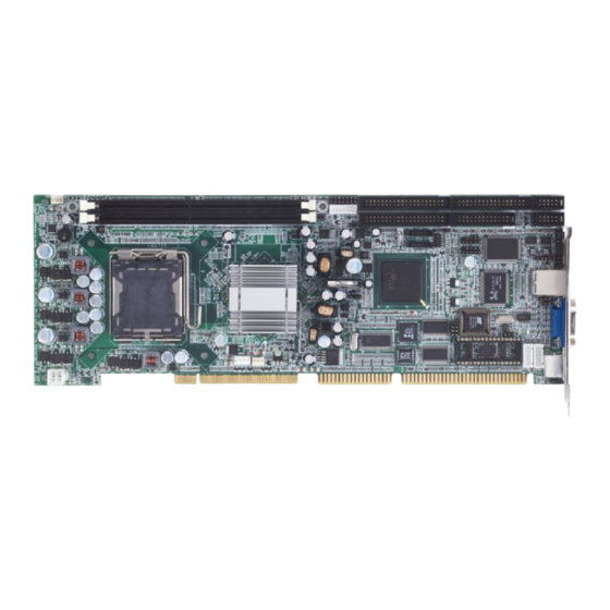
Summary of Contents for AXIOMTEK SBC81202VG
- Page 1 SBC81202VG ® Intel PentiumD/Pentium4/Celeron D PICMG 1.0 Single Board Computer User’s Manual...
-
Page 2: Disclaimers
Disclaimers The information in this manual has been carefully checked and is believed to be accurate. AXIOMTEK Co., Ltd. assumes no responsibility for any infringements of patents or other rights of third parties which may result from its use. AXIOMTEK assumes no responsibility for any inaccuracies that may be contained in this document. -
Page 3: Esd Precautions
Wear a wrist-grounding strap, available from most electronic component stores, when handling boards and components. Trademarks Acknowledgments AXIOMTEK is a trademark of AXIOMTEK Co., Ltd. IBM is a registered trademark of International Business Machines Corporation. MS-DOS, and Windows 2000 are trademarks of Microsoft Corporation. -
Page 4: Table Of Contents
T a b l e o f C o n t e n t s Disclaimers ............ii ESD Precautions ........... iii Chapter 1 Introduction ............1 General Description ........1 Specifications ..........2 Utilities Supported ......... 3 Board Dimensions ......... 4 Chapter 2 Jumpers and Connectors ........ - Page 5 IrDA Connector..........24 4.10 5VSB Power Connector Connector ....25 4.11 ATX12V Power Connector: CN25 ....25 Chapter 5 Installing VGA driver ......... 27 Introduction ..........27 Driver Disks’ Contents ......... 27 Windows 2000 VGA Driver Installation ..27 Windows XP VGA Driver Installation .... 29 Chapter 6 Installing LAN Driver........
-
Page 7: Chapter 1 Introduction
SBC81202VG LGA775 SBC User Manual Chapter 1 Introduction General Description The SBC81202VG PICMG 1.0 Single Board Computer delivers new features for interactive application and many other embedded computing solutions requiring higher performance.it support two 184-pin DDR DIMM sockets and support the maximum memory capacity could up to 2GB .VGA function with Intel®... -
Page 8: Specifications
SBC81202VG LGA775 SBC User Manual Specifications ® Processor: Intel Pentium D/Pentium4/Celeron ® North Bridge: Intel 82865G ® South Bridge: Intel 82801EB(ICH5) CPU Socket: LGA775 : 533/800 Mhz L2 Cache: Integrated in CPU Pentium D = 2M x 2/Pentium 4 = 1M or 2M/Celeron D = 256K or 512K BIOS: Phoenix AwardBIOS Rev.6.00... -
Page 9: Utilities Supported
SBC81202VG LGA775 SBC User Manual Hardware Monitoring: Winbond W83627HG-AW detection of CPU temperature, System temperature, Power failure and Fan speed. Watchdog Timer: Software programmable time interval and hardware reset only. 255 level, 1~255 seconds Dimensions:338 mmx122mm(6 Layer) NOTE: Specifications are subject to change without notice. -
Page 10: Board Dimensions
SBC81202VG LGA775 SBC User Manual Board Dimensions Introduction... -
Page 11: Chapter 2 Jumpers And Connectors
SBC81202VG LGA775 SBC User Manual Chapter 2 Jumpers and Connectors Board Layout Jumpers and Connectors... -
Page 12: Jumper Settings
SBC81202VG LGA775 SBC User Manual Jumper Settings Fllowed as below detailed description for Jumper setting and installed the SBC81202 on your application Jumper Description RS232 Setting Clear CMOS Setting Disk On Chip Setting Watchdog Trigger Mode External Keyboard Wake up... -
Page 13: Clear Cmos Setting: Jp5
SBC81202VG LGA775 SBC User Manual 2.2.1 COM2 RS232 Settings: JP1, JP2,JP4 COM2 RS-232 Short 3-5,4-6 Short 3-5,4-6 Short 1-2,7-8 (Default) 2.2.2 Clear CMOS Setting: JP5 Options Settings Normal 1-2(Default) Clear CMOS Jumpers and Connectors... -
Page 14: Disk On Chip Setting: Jp6
SBC81202VG LGA775 SBC User Manual 2.2.3 Disk on Chip Setting: JP6 Options Settings D0000-D1FFF Short 1-2(Default) D2000-D3FFF D4000-D5FFF D6000-D7FFF 2.2.4 Watchdog Tigger Mode: JP7 Options Settings RESET Disabled Open (Default) 2.2.5 External KB Wake up: JP8 Options Settings Normal 1-2(Default) -
Page 15: Connectors
SBC81202VG LGA775 SBC User Manual 2.3 Connectors The connectors allow the CPU card to connect with other parts of the system. Some problems encountered by your system may be a result from loose or improper connections. Ensure that all connectors are in place and firmly attached. -
Page 16: Chapter 3 Installation
SBC81202VG LGA775 SBC User Manual Chapter 3 Installation Before installing the processor, Please pay moe attention on Intel website and obtained more information http://www.intel.com. 3.1 CPU Installation LGA775 processor socket come with a lever to protect the processor.Please pay more attention as below.Follow the pictures and place the processor into CPU socket. - Page 17 SBC81202VG LGA775 SBC User Manual Installation...
- Page 18 SBC81202VG LGA775 SBC User Manual Installation...
- Page 19 SBC81202VG LGA775 SBC User Manual Installation...
- Page 20 SBC81202VG LGA775 SBC User Manual Installation...
- Page 21 SBC81202VG LGA775 SBC User Manual Installation...
- Page 22 SBC81202VG LGA775 SBC User Manual Installation...
-
Page 23: Installing Atx Power Upply
SBC81202VG LGA775 SBC User Manual Installing ATX Power Supply System power is provided to the SBC81202 Single Board Computer by CN25 3.3 Installing the Memory SBC81202 support DDR memory and support the maximum memory capacity could up to 2GB.If you want to know what is difference between DDR and DDR2.See below... -
Page 24: Chapter 4 Hardware Description
SBC81202VG LGA775 SBC User Manual Chapter 4 Hardware Description This chapter provided detailed information for all of hardware features for SBC81202 all-in-one LGA775 CPU card. 4.1 General Output Connector:CN3 Power LED Defined by Pins 1, 3, 5, 7 connects the system power LED indicator to its respective switch on the case. - Page 25 SBC81202VG LGA775 SBC User Manual Power Botton This 2-pin connector was designed at Pin9/10 4.2 Enhane IDE interface connecotor-CN4 and CN8 SBC81202 provided two IDE Port and support the maximum IDE devices could up to four IDE devices. Description Description...
-
Page 26: Enhane Ide Interface Connecotor-Cn4/Cn8
SBC81202VG LGA775 SBC User Manual 4.3 Display interface-CN19 The GMCH provides interfaces to a progressive scan analog monitor and DVO can drive a variety of DVOdevices• The GMCH has an integrated 350 MHz RAMDAC that can directly drive a progressive scananalog monitor up to a resolution of 2048x1536 at 75 Hz. -
Page 27: Parallel Port Interface:cn9
SBC81202VG LGA775 SBC User Manual Description Description Description Reduce write Current Index # Motor enable A # Drive Select B # Drive select A # Motor enable B # Direction # STEP # Write data # Write gate # Track #... -
Page 28: Serial Port Interface
SBC81202VG LGA775 SBC User Manual Strobe # Auto Form Feed # Data 0 Error # Data 1 Initialize # Data 2 Printer Select In # Data 3 Data 4 Data 5 Data 6 Data 7 Acknowledge # Busy Paper Empty #... -
Page 29: Keyboard And Ps/2 Mouse Connectors
SBC81202VG LGA775 SBC User Manual (DTR) Ring Indicator(RI) Keyboard and PS/2 Mouse Connectors SBC81202 provides a keyboard (CN21) and Mouse (CN20) interface with two 5-pin connectors. Clock Data No Connection Power Mini-Din Connecter Hardware Description... -
Page 30: Usb Connector
SBC81202VG LGA775 SBCUser Manual 4.10 USB Connector The Universal Serial Bus (USB) connector was used for the USB interface. CN12/CN14 is the 9-pin USB connector on the SBC81202. Power AGND Power 4.11 IrDA Connector CN15 is a 5-pin IrDA connector for wireless communication. -
Page 31: 5Vsb Power Connector Connector
SBC81202VG LGA775 SBC User Manual 4.12 5VSB Power Connector Connector The interface enables and supports reliable power anagement through improved hardware and operating system coordination. The specification enables new power management technology to evolve independently in operating systems and hardware while ensuring that they continue to work together. - Page 32 SBC81202VG LGA775 SBCUser Manual 300W for a fully configured system. The system may become unstable and may experience difficulty powering up if the power supply is inadequate. Hardware Description...
-
Page 33: Chapter 5 Installing Vga Driver
SBC81202VG LGA775 SBC User Manual Chapter 5 Installing VGA driver Introduction The GMCH provides interfaces to a progressive scan analog monitor. The GMCH has an integrated 350 MHz RAMDAC that can directly drive a progressive scananalog monitor up to a resolution of 2048x1536 at 75 Hz. - Page 34 SBC81202VG LGA775 SBCUser Manual To install or upgrade the Intel 865G video driver: Run SETUP.EXE from the driver directory on your drivers Follow the onscreen directions to complete installation. There may be messages about the driver not having a digital signature, select Yes to all these message boxes.
-
Page 35: Windows Xp Vga Driver Installation
SBC81202VG LGA775 SBC User Manual Windows XP VGA Driver Installation To install video support If you have installed retail Windows you need to install the video driver. The driver is contained in the \SBC81202\Drivers\VGA subdirectory on the dirvers CD. To install or upgrade the video driver: 1. -
Page 36: Chapter 6 Installing Lan Driver
SBC81202VG LGA775 SBCUser Manual Chapter 6 Installing LAN Driver Introduction SBC81202 was built-in high performance Plug and Play Ethernet interface which is fully compliant with the IEEE 802.3 standard, and consisting of the RJ-45 connector Features 10/100/1000BASE-T Triple-speed MAC PCI host interface... -
Page 37: Chapter 7 Award Bios Utility
SBC81202VG LGA775 SBC User Manual Chapter 7 Award BIOS Utility Please pay more time and check all of detailed information for BIOS settings available in the Award BIOS that comes with the SBC81202 CPU card. 7.1 BIOS Introduction The Award BIOS (Basic Input/Output System) installed in your computer system ’... - Page 38 SBC81202VG LGA775 SBC User Manual The section below the setup items of the Main Menu displays the control keys for this menu. Another section located at the bottom of the Main Menu, just below the control keys section, displays information on the currently highlighted item in the list.
-
Page 39: Standard Cmos Setup
SBC81202VG LGA775 SBC User Manual Standard CMOS Setup “ Standard CMOS Setup ” allows you to record some basic hardware configurations in your computer system and set the system clock and error handling. If the motherboard is already installed in a working system, you will not need to select this option. - Page 40 SBC81202VG LGA775 SBC User Manual Date The date format is <day>, <month>,<date>, <year>. Press <F3> to show the calendar. The day of week, from Sun to Sat, determined by the BIOS, is read only The date, from 1 to 31 (or the maximum allowed in...
- Page 41 SBC81202VG LGA775 SBC User Manual Drive A type/Drive B type The category identifies the types of floppy disk drive A or drive B installed in the computer. None No floppy drive installed 360K, 5.25 in 5.25 inch PC-type standard drive; 360Kb capacity 1.2M, 5.25 in...
-
Page 42: Advanced Bios Features
SBC81202VG LGA775 SBC User Manual Advanced BIOS Features This section allows you to configure and improve your system and allows you to set up some system features according to your preference. 7.3.1 CPU Feature Clicks the cursor to this fild and press <Enter>. The following screen Will be appeared. - Page 43 SBC81202VG LGA775 SBC User Manual The setting on the screen are for reference only. Your version may not be identical to this one. Delay prior to Thermal This filed is used to select the time that would force the CPU to a...
-
Page 44: Hard Disk Boot Priority
SBC81202VG LGA775 SBC User Manual May occur. To avoid this problem, enable this field to limit the return value to 3 or lesser than 3. 7.3.2 Hard Disk Boot Priority This field is used to select the boot sequence of the hard drives. -
Page 45: Swap Floppy Drive
SBC81202VG LGA775 SBC User Manual First/Second/Third Boot Device These items allow the selection of the 1 , and 3 devices that the system will search for during its boot-up sequence. The wide range of selection includes Floppy, LS120, ZIP100, HDD0~3, SCSI, and CDROM. - Page 46 SBC81202VG LGA775 SBC User Manual Tyematic Rate Setting Disabled Contiunally holding down a key on your keyboard will cause the BIOS to report that the key is down. Enabled The BIOS will not only report that the key is down, but...
- Page 47 SBC81202VG LGA775 SBC User Manual OS Select for DRAM >64MB This field allows you to access the memory that is over 64MB in OS/2. Small Logo(EPA) Show Enabled The EPA logo will appear during system boot up. Disabled The EPA logo will not appear during system boot-up.
-
Page 48: Advanced Chipset Features
SBC81202VG LGA775 SBC User Manual Advanced Chipset Features Since the features in this section are related to the chipset on the CPU board and are completely optimized, you are not recommended to change the default settings in this setup table unless you are well oriented with the chipset features. - Page 49 SBC81202VG LGA775 SBC User Manual Manual If you want better performance for your system other than the one “ by SPD “ select “ Manual “ then select the best option in the “ CAS Latency Time “ to “ System Memory Frequency “ fields.
- Page 50 SBC81202VG LGA775 SBC User Manual Init Display First This item allows you to decide to active whether PCI Slot or on- chip VGA first. On-Board LAN function This item allows you to Disabled or Enabled onboard LAN On-Chip VGA Setting...
-
Page 51: Integrated Peripherals
SBC81202VG LGA775 SBC User Manual Integrated Peripherals This option sets your hard disk configuration, mode and port. 7.5.1 On-Chip IDE Device Move the cursor to this field and press <Enter>. The following screen will be appeared. Award Bios Setup... - Page 52 SBC81202VG LGA775 SBC User Manual IDE HDD Block Mode Enabled The IDE HDD uses the block mode. The system BIOS will check the hard disk drive for the maximum block size the system can transfer. The block size will depend on the type of hard disk drive.
- Page 53 SBC81202VG LGA775 SBC User Manual Auto The system will detect the existing SATA and IDE drives then automatically se them To the available Master / Slave Mode. Combined Mode This option allows you to use both IDE and SATA drives; allowing a maximum od 4 drives-1 IDE Master;...
-
Page 54: Onboard Device
SBC81202VG LGA775 SBC User Manual show “ P0, P2 is Primary “; meaning SATA 1 and SATA 3 are Primary. 7.5.2 Onboard Device Move the cursor to this field and press <Enter>. The following Screen will be appeared. USB Controller... -
Page 55: Super Io Device
SBC81202VG LGA775 SBC User Manual 7.5.3 Super IO Device Move the cursor to this field and press < Enter >. The following screen will be appeared. Onboard Serial Port 1/Port 2 Select an address and corresponding interrupt for the first and second serial ports. - Page 56 SBC81202VG LGA775 SBC User Manual Mouse Click When this option is selected, click the mouse button to power on the system. Any Key Press any key to power on the system. Keyboard 98 When this option is selected, press the “...
- Page 57 SBC81202VG LGA775 SBC User Manual Onboard Parallel Port 378/IRQ7, 3BC/IRQ7, 278/IRQ5 Select the I/O address and IRQ for the onboard parallel port. Disabled Disables the onboard parallel port. Parallel Port Mode The options are SPP, EPP, ECP and ECP+EPP. These apply to a Standard specification and will depend on the type and speed of You device.
-
Page 58: Power Management Setup
SBC81202VG LGA775 SBC User Manual Power Management Setup The Power Management Setup allows you to save energy of your system effectively. It will shut down the hard disk and turn OFF video display after a period of inactivity. ACPI Function This function ahould be enabled only in operating systems that support ACPI. - Page 59 SBC81202VG LGA775 SBC User Manual Max Saving Maximum power saving time for the Suspend Mode and HDD Power Down =1 min. User Define Allows you to set the power saving time in the “ Suspend Mode “ and “ HDD Power Down “...
- Page 60 SBC81202VG LGA775 SBC User Manual Pressing the power button for more than 4 seconds forces the system to enter the Soft-Off state when the system has “hung.” The choice: Delay 4 Sec, Instant-Off. Wake-Up By PCI card If this item is enable, it allows the system to resume from a software power down or power saving mode whenever there is an Incoming call to an installed fax/modem.
-
Page 61: Pnp/Pci Configuration
SBC81202VG LGA775 SBC User Manual PNP/PCI Configuration This section describes configuring the PCI bus system. PCI, or Personal Computer Interconnect, is a system which allows I/O devices to operate at speeds nearing the speed the CPU itself uses when communicating with its own special components. - Page 62 SBC81202VG LGA775 SBC User Manual Resource controlled by The Award Plug and Play BIOS has the capacity to automatically configure all of the boot and Plug and Play compatible devices. However, this capability means absolutely nothing unless you are using a Plug and Play operating system such as Windows®98.
-
Page 63: Pc Health Status
SBC81202VG LGA775 SBC User Manual PC Health Status This option configures the PCI bus system. All PCI bus systems on the system use INT#, thus all installed PCI cards must be set to this value. Current Power Temperature. The current system power will be detected automatically. -
Page 64: Frequency/Voltage Control
SBC81202VG LGA775 SBC User Manual Show you the current system fan1 temperature. +3.3V/+5V/+12V/-12V/-5V/VBAT(V)/5VSB Show you the voltage of +3.3V/+5V/+12V/-12V/-5V. Frequency/Voltage Control CPU Clock Ratio This field is used to select the CPU’s frequency Auto Detect PCI Clk Leave this field in its default setting. Do not alter this setting unless advised by an engineer or technician. -
Page 65: Load Optimized Defaults
SBC81202VG LGA775 SBC User Manual 7.10 Load Optimized Defaults When you press <Enter> on this item you get a confirmation dialog box with a message similar to: Load Optimized Defaults (Y/N)? N Pressing “ Y ” loads the default values that are factory settings for optimal performance system operations 7.11 Supervisor/User Password Setting... -
Page 66: Exit Setting
SBC81202VG LGA775 SBC User Manual the BIOS to request a password every time your system is rebooted.This would prevent unauthorized use of your computer. You determine when the password is required within the BIOS Features Setup Menu and its Security option (see Section 3). -
Page 67: Appendix A Watchdog Timer
SBC81202VG LGA775 SBC User Manual A p p e n d i x A Watchdog Timer Please follow the below WDT process for setup the WDT function. A Watchdog Timer... -
Page 68: Appendix B Pci Irq Routing
SBC81202VG LGA775 SBC User Manual A p p e n d i x B PCI IRQ Routing PICMG PCI IRQ Routing Device Slot PCI Slot 0 BCDA PCI Slot 1 CDAB PCI Slot 2 DABC PCI Slot 3 ABCD On Board Device IRQ Routing...
Need help?
Do you have a question about the SBC81202VG and is the answer not in the manual?
Questions and answers