
Related Manuals for AXIOMTEK SBC86831 Series


Summary of Contents for AXIOMTEK SBC86831 Series
- Page 1 SBC86831 Series Intel® Core 2 Duo All-In-One Mini ITX Board with DualView display User’s Manual Introduction...
- Page 2 AXIOMTEK does not warrant or assume any legal liability or responsibility for the accuracy, completeness or usefulness of any information in this document. AXIOMTEK does not make any commitment to update the information in this manual.
- Page 3 Wear a wrist-grounding strap, available from most electronic component stores, when handling boards and components. Trademarks Acknowledgments AXIOMTEK is a trademark of AXIOMTEK Co., Ltd. ® Windows is a trademark of Microsoft Corporation. Phoenix & AWARD are trademarks of Phoenix Technology Ltd.
-
Page 4: Table Of Contents
Table of Contents Disclaimers ................. ii ESD Precautions................ iii Chapter 1 Introduction ..............1 Specifications ..............2 Utilities Supported ............4 Chapter 2 Jumpers and Connectors ..........5 Board Layout and Fixing Holes ........5 Placement................. 7 Jumper Settings..............9 2.3.1 COM1 Mode Select Jumper ........ - Page 5 2.4.16 ATX Power Connector ..........26 2.4.17 +12V ATX Power Connector ........27 2.4.18 Compact Flash Socket ......... 27 2.4.19 PCI-Express Mini Card Socket ....... 28 2.4.20 System & CPU FAN Connectors ......30 2.4.21 SMBUS Connector..........30 2.4.22 Slim PCI Slot ............30 2.4.23 PCI-Express X16 Slot ..........
- Page 6 MEMO...
-
Page 7: Chapter 1 Introduction
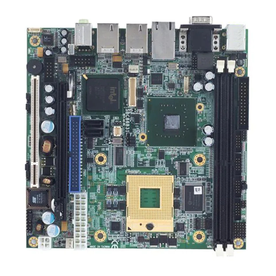
SBC86831 Series All-In-One Mini ITX Board User’s Manual C h a p t e r 1 Introduction The SBC86831, a Mini ITX board, supports Intel® Core 2 Duo, Core Duo, Core Solo and Celeron M processors with graphics, audio, and Gigabit Ethernet interfaces. -
Page 8: Specifications
SBC86831 Series All-In-One Mini ITX Board User’s Manual Specifications ® CPU: Socket M (478-pin) for Intel Core 2 Duo, Core ® Duo, Core Solo and Celeron M processors ® Chipset: Intel 945GME & ICH7M Bus Clock: 533/667MHz FSB BIOS: Phoenix-Award BIOS, Y2K compliant... - Page 9 SBC86831 Series All-In-One Mini ITX Board User’s Manual Maximum up to 224MB frame buffer sharing system memory Maximum display resolution: CRT: 2048 x1536 LVDS: 1600 X1200 (24-bit single/dual channel LVDS interface) DualView display mode: CRT: 2048 x1536 LVDS: 1600 X1200 (24-bit single/dual channel LVDS...
-
Page 10: Utilities Supported
SBC86831 Series All-In-One Mini ITX Board User’s Manual Utilities Supported Chipset Driver Ethernet Driver Graphic Drivers Audio Drivers Introduction... -
Page 11: Chapter 2 Jumpers And Connectors
SBC86831 Series All-In-One Mini ITX Board User’s Manual C h a p t e r 2 Jumpers and Connectors Board Layout and Fixing Holes Component Side Jumpers and Connectors... - Page 12 SBC86831 Series All-In-One Mini ITX Board User’s Manual Solder Side Jumpers and Connectors...
-
Page 13: Placement
SBC86831 Series All-In-One Mini ITX Board User’s Manual Placement Component Side Jumpers and Connectors... - Page 14 SBC86831 Series All-In-One Mini ITX Board User’s Manual Solder Side Jumpers and Connectors...
-
Page 15: Jumper Settings
SBC86831 Series All-In-One Mini ITX Board User’s Manual Jumper Settings Proper jumer settings configure the SBC86831 to meet your application purpose. We are herewith listing a summary table of all jumpers and default settings for onboard devices, respectively. Here is a list of jumper settings:... -
Page 16: Com1 Mode Select Jumper
SBC86831 Series All-In-One Mini ITX Board User’s Manual 2.3.1 COM1 Mode Select Jumper: JP1 These jumpers select the COM1 port’s communication mode to operate RS-232 or RS-422/485. Options Settings RS-232 Short 1-2 (Default) RS-422 Short 3-4 RS-485 Short 5-6,7-8 2.3.2... -
Page 17: Cpu Frequency Selec Jumpers
SBC86831 Series All-In-One Mini ITX Board User’s Manual COM1 (CN7) COM2 (CN2) Pin 1=12V Short 1-3 Pin 1=12V Short 1-3 Pin 1=5V Short 3-5 or 5-7 Pin 1=5V Short 3-5 or 5-7 *Pin 1=DCD Short 7-9 (Default) *Pin 1=DCD Short 7-9 (Default) -
Page 18: Lvds Voltage Selection Jumper
SBC86831 Series All-In-One Mini ITX Board User’s Manual 2.3.6 LVDS Voltage Selection Jumper: JP11 This jumper is to select the voltage for LVDS interface. JP11 Options Settings 3.3V Short 1-2 (Default) Short 2-3 2.3.7 SDVO Card Selection Jumper: JP12 This jumper makes the selection that PCI express x 16 slot enables or disables the SDVO mode. -
Page 19: Compact Flash Setting Jumper
SBC86831 Series All-In-One Mini ITX Board User’s Manual 2.3.10 Compact Flash Setting Jumper: JP16 This jumper is to select the master or slave for Compact Flash interface. JP16 Options Settings Slave Short 1-2 (Default) Master Short 2-3 This jumper is optional. It is not mounted by default design. -
Page 20: Connectors
SBC86831 Series All-In-One Mini ITX Board User’s Manual Connectors Connectors connect the board with other parts of the system. Loose or improper connection might cause problems. Make sure all connectors are properly and firmly connected. Here is a summary table shows you all connectors on the SBC86831 Series. -
Page 21: Parallel Port Or Floppy Connector
SBC86831 Series All-In-One Mini ITX Board User’s Manual Slim PCI Slot PCI1 PCI- EXPRESS X16 Slot PCIE1 2.4.1 Parallel Port or Floppy Connector: CN1 Print Port Connector [Default] This board has a multi-mode parallel port to support: 1. Standard mode: IBM PC/XT, PC/AT and PS/2™... -
Page 22: Serial Port Connectors
SBC86831 Series All-In-One Mini ITX Board User’s Manual Floppy Connector [Optional] The FDD connector is used connect the FDD cable while the other end of the cable connects to the FDD drive. The type of FDD drives supported are : 360KB, 720KB,1.2MB,1.44MB and 2.88MB. -
Page 23: Digital I/O Port (Dio) Connector
SBC86831 Series All-In-One Mini ITX Board User’s Manual 2.4.3 Digital I/O Port (DIO) Connector: CN5 The board is equipped an 8-channel digital I/O connector CN5 that meets requirements for a system customary automation control. The digital I/O can be configured to control cash drawers, sense warning signals from an Uninterrupted Power System (UPS), or perform store security control. -
Page 24: Vga & Serial Port 1 Connectors
SBC86831 Series All-In-One Mini ITX Board User’s Manual 2.4.5 VGA & Serial Port 1 Connectors: CN7A, CN7B CN7 is double deck D-Sub connector. The upper is a standard 9-pin pin DB9 connector for the Serial port 1(CN7A). CN7A is RS-232/422/485, jumper selectable with auto flow control features. -
Page 25: Lvds Backlight Connector
SBC86831 Series All-In-One Mini ITX Board User’s Manual 2.4.6 LVDS Backlight Connector: CN8 The 7-pin inverter connector on the SBC is with Hirose connector. The matching connector is strongly recommended to use Hirose DF13-7S-1.25C. Signal +12V +12V ENABLE 2.4.7 LAN*2 Connectors: CN9_A, CN9_B The board is equipped with a high performance Plug and Play Ethernet interface fully compliant with the IEEE 802.3 standard. -
Page 26: Usb*2+Iee1394A Connectors
Active LED (Yellow) 1000 (Orange) / 100 (Green) LAN 2.4.8 USB*2+IEE1394a Connectors: CN10, CN13 The SBC86831 Series have three layers USB &IEE1394a Connector (CN10, CN13) & two box-header connectors (CN17,CN19). The upper is IEE1394a connector (CN10A, CN13A).Serial interface standard set by institute of Electrical and Electronics Engineers, which has features like high speed, high bandwidth and hot plug. - Page 27 SBC86831 Series All-In-One Mini ITX Board User’s Manual Signal CN10B USB D0- USB D0+ USB D1- USB D1+ Signal CN13A +12V XTPB1N XTPB1P 1 3 5 XTPA1N XTPAP Signal CN13B USB D2- USB D2+ USB D3- USB D3+ Jumpers and Connectors...
-
Page 28: Sata Connectors
SBC86831 Series All-In-One Mini ITX Board User’s Manual 2.4.9 LVDS Flat Panel Connector: CN11 The LVDS connector on the SBC is a 40-pin connector. The matching connector is strongly recommended to use JST SHDR-40V-S-B. Signal Signal VCCM VCCM CN11 VCCM... -
Page 29: Usb Connectors
SBC86831 Series All-In-One Mini ITX Board User’s Manual 2.4.11 Audio Phone Jack Connector: CN16 After install onboard audio driver, you may connect speaker to Line Out jack, microphone to MIC in jack. CN16 Signal Ground (GND) VREFOUT Ground (GND) MIC_IN... -
Page 30: Parallel Ide Connector
SBC86831 Series All-In-One Mini ITX Board User’s Manual 2.4.13 Parallel IDE Connector: CN18 An IDE device connects to the computer via an IDE connector. One IDE connector can connect to one IDE cable, and the single IDE cable can then connect to two IDE devices. If you wish to connect two IDE devices, please set the jumper on one IDE device as Master and the other as Slave. -
Page 31: Flat Panel Bezel Connector
SBC86831 Series All-In-One Mini ITX Board User’s Manual 2.4.14 Flat Panel Bezel Connector: CN20 8 10 12 14 9 11 13 Power LED This 3-pin connector named as Pin 1 and Pin 5 connect the system power LED indicator to such a switch on the case. Pin 1 is assigned as +, and Pin 5 as -. -
Page 32: Internal Audio Connector
SBC86831 Series All-In-One Mini ITX Board User’s Manual 2.4.15 Internal Audio Connector: CN21 The SBC86831 supports internal audio interface. CN21 is a 5pin- header connector commonly used for the audio. After install onboard audio driver, you may connect speaker to Line Out jack, microphone to MIC in jack. -
Page 33: Atx Power Connector
2.4.18 Compact Flash Socket: CFS1 (Optional) The SBC86831 Series is equipped with a Compact Flash disk type-II socket on the solder side and it supports the IDE interface Compact Flash disk card with DMA mode supported. The socket itself is especially designed to prevent any incorrect installation of the Compact Flash disk card. -
Page 34: Pci-Express Mini Card Socket
SBC86831 Series All-In-One Mini ITX Board User’s Manual Signal Signal Address 10 VS1- ATASEL IORD- Address 9 IOWR- Address 8 Address 7 INTR Address 6 CSEL- Address 5 VS2- Address 4 RESET- Address 3 IORDY- Address 2 DMAREQ Address 1... - Page 35 SBC86831 Series All-In-One Mini ITX Board User’s Manual Signal Signal PCIE_WAKE- +3.3V +1.5 V PCIE_CLK- PCIE_CLK+ PCIE_RESET- PCIE_RXN +3.3V_SBY PCIE_RXP +1.5V SMB_CLK PCIE_TXN SMB_DATA PCIE_TXP USB_D- USB_D+ Jumpers and Connectors...
-
Page 36: System & Cpu Fan Connectors
2.4.20 System & CPU FAN Connectors: FAN1, FAN2 FAN1 is system fan connector, and FAN2 is CPU fan connector. Pentium microprocessors require a fan for heat dispensing. The fan connector on SBC86831 Series provides power to the fan. Signal FAN1, FAN2... - Page 37 SBC86831 Series All-In-One Mini ITX Board User’s Manual Signal Signal Signal Signal A1 TRST- +12V -12V A3 TMS A5 +5V INTA- A7 INTC- INTB- INTD- A9 N.C A10 +5V B10 REQ1- A11 N.C A12 GND B11 N.C B12 GND A13 GND...
-
Page 38: Pci-Express X16 Slot
SBC86831 Series All-In-One Mini ITX Board User’s Manual 2.4.23 PCI-Express X16 Slot: PCIE1 PCIE1 is a PCI-Express x16 graphics interface, It can support PCI- Express x16 graphics card (PCI-Express x16), and Add2 card(SDVO Bus). But it can only 2 select 1.And The Add2 card (SDVO Bus) by default design. - Page 39 SBC86831 Series All-In-One Mini ITX Board User’s Manual Signal Signal Signal Signal A23 GND A24 GND PEG_TXP2 PEG_TXN2 N.C (Default) N.C (Default) PEG_RXP2 PEG_RXN2 B25 GND B26 GND SDVO_FLD SDVO_FLDS STALL+ TALL- (Default) (Default) A27 GND A28 GND PEG_TXP3 PEG_TXN3 N.C (Default)
- Page 40 SBC86831 Series All-In-One Mini ITX Board User’s Manual Signal Signal Signal Signal PEG_RXP7 PEG_RXN7 B47 GND B48 MCH_CFG_2 N.C (Default) (Default) A49 GND A50 N.C B49 GND PEG_TXP8 N.C (Default) A51 GND PEG_RXP8 PEG_TXN8 B52 GND N.C (Default) N.C (Default)
- Page 41 SBC86831 Series All-In-One Mini ITX Board User’s Manual Signal Signal Signal Signal A75 GND PEG_RXP14 PEG_TXN14 B76 GND N.C (Default) N.C (Default) PEG_RXN1 A78 GND B77 GND PEG_TXP15 N.C (Default) (Default) A79 GND PEG_RXP15 PEG_TXN15 B80 GND N.C (Default) N.C (Default)
- Page 42 SBC86831 Series All-In-One Mini ITX Board User’s Manual MEMO Jumpers and Connectors...
-
Page 43: Chapter 3 Hardware Description
Make sure your installed microprocessor with all correct settings that prevents the CPU from damages. BIOS The SBC86831 Series uses Award Plug and Play BIOS with a single 4Mbit Flash EPROM. System Memory The SBC86831 Series industrial CPU card supports two 240-pin DDR2 DIMM sockets for a maximum memory of 3GB DDR2 SDRAMs. -
Page 44: I/O Port Address Map
SBC86831 Series All-In-One Mini ITX Board User’s Manual I/O Port Address Map The Intel® Pentium III/Celeron® M CPUs can communicate via I/O ports. There are total 1KB port addresses available for assignment to other devices via I/O expansion cards. Address... -
Page 45: Interrupt Controller
SBC86831 Series All-In-One Mini ITX Board User’s Manual Interrupt Controller The SBC86831 Series is a 100% PC compatible control board. It consists of 16 interrupt request lines, and four out of them can be programmable. The mapping list of the 16 interrupt request lines is shown as the following table. - Page 46 SBC86831 Series All-In-One Mini ITX Board User’s Manual MEMO Hardware Description...
-
Page 47: Chapter 4 Award Bios Utility
SBC86831 Series All-In-One Mini ITX Board User’s Manual C h a p t e r 4 Award BIOS Utility The Phoenix-Award BIOS provides users with a built-in Setup program to modify basic system configuration. All configured parameters are stored in a battery-backed-up RAM (CMOS RAM) to save the Setup information whenever the power is turned off. -
Page 48: Control Keys
SBC86831 Series All-In-One Mini ITX Board User’s Manual Control Keys Move cursor to the previous item Up arrow Move cursor to the next item Down arrow Move cursor to the item on the left hand Left arrow Move to the item in the right hand... -
Page 49: The Main Menu
SBC86831 Series All-In-One Mini ITX Board User’s Manual The Main Menu Once you enter the Award BIOS CMOS Setup Utility, the Main Menu appears on the screen. In the Main Menu, there are several Setup functions and a couple of Exit options for your selection. Use arrow keys to select the Setup Page you intend to configure then press <Enter>... -
Page 50: Standard Cmos Setup Menu
SBC86831 Series All-In-One Mini ITX Board User’s Manual Standard CMOS Setup Menu The Standard CMOS Setup Menu displays basic information about your system. Use arrow keys to highlight each item, and use <PgUp> or <PgDn> key to select the value you want in each item. - Page 51 SBC86831 Series All-In-One Mini ITX Board User’s Manual IDE Primary Master/Primary Slave These items identify the types of each IDE channel installed in the computer. There are 45 predefined types (Type 1 to Type 45) and 2 user’s definable types (Type User) for Enhanced IDE BIOS.
- Page 52 SBC86831 Series All-In-One Mini ITX Board User’s Manual Halt On The system booting will halt on any errors detected. No errors (default) Whenever BIOS detects a non-fatal error, the All errors system will stop and you will be prompted. The system booting will not stop for a keyboard All, But error;...
-
Page 53: Advanced Bios Features
SBC86831 Series All-In-One Mini ITX Board User’s Manual Advanced BIOS Features This section allows you to configure and improve your system, to set up some system features according to your preference. CPU Feature Scroll to this item and press <Enter> to view the CPU Feature sub menu. - Page 54 SBC86831 Series All-In-One Mini ITX Board User’s Manual Hard Disk Boot Priority Scroll to this item and press <Enter> to view the sub menu to decide the disk boot priority. CPU L1 & L2 Cache These two options speed up memory access. However, it depends on the CPU/chipset design.
- Page 55 SBC86831 Series All-In-One Mini ITX Board User’s Manual These items let you select the 1st, 2nd, and 3rd devices that the system will search for during its boot-up sequence. The wide range of selection includes Floppy, LS120, ZIP100, HDD0~3, SCSI, and CDROM.
- Page 56 SBC86831 Series All-In-One Mini ITX Board User’s Manual Typematic Rate Setting Enabled Enable typematic rate and typematic delay programming. Disable typematic rate and typematic delay Disabled programming. The system BIOS will use default value of these 2 items, controlled by keyboard.
- Page 57 SBC86831 Series All-In-One Mini ITX Board User’s Manual just press <Enter> and it will disable the security. Once the security is disabled, the system will boot and you can enter Setup freely. APIC Mode Use this item to enable or disable APIC (Advanced Programmable Interrupt Controller) mode that provides symmetric multi- processing (SMP) for systems.
-
Page 58: Advanced Chipset Features
SBC86831 Series All-In-One Mini ITX Board User’s Manual Advanced Chipset Features This section contains completely optimized chipset’s features on the board that you are strongly recommended to leave all items on this page at their default values unless you are very familiar with the technical specifications of your system hardware. - Page 59 SBC86831 Series All-In-One Mini ITX Board User’s Manual PCI Express Root Port Func Scroll to this item and press <Enter> to view the sub menu to decide the PCI Express Port. Press <Esc> to return to the Advanced Chipset Featurs page, and press it again, return to the Main Menu page.
-
Page 60: Integrated Peripherals
SBC86831 Series All-In-One Mini ITX Board User’s Manual Integrated Peripherals This section allows you to configure your SuperIO Device, IDE Function and Onboard Device. OnChip IDE Device Scroll to this item and press <Enter> to view the sub menu OnChip IDE Device. - Page 61 SBC86831 Series All-In-One Mini ITX Board User’s Manual detection of the optimal number of block read/writes per sector the drive can support. IDE DMA transfer access Automatic data transfer between system memory and IDE device with minimum CPU intervention. This improves data throughput and frees CPU to perform other tasks.
- Page 62 SBC86831 Series All-In-One Mini ITX Board User’s Manual Onboard Device Scroll to this item and press <Enter> to view the sub menu Onboard Device. USB Controller Enable this item if you are using the USB in the system. You should disable this item if a higher-level controller is added.
- Page 63 SBC86831 Series All-In-One Mini ITX Board User’s Manual Super IO Device Scroll to this item and press <Enter> to view the sub menu Super IO Device. Onboard FDC Controller Select Enabled if your system has a floppy disk controller (FDC) installed on the system board and you wish to use it.
-
Page 64: Power Management Setup
SBC86831 Series All-In-One Mini ITX Board User’s Manual ECP mode. PWRON After PWR-Fail This item enables your computer to automatically restart or return to its operating status. Press <Esc> to return to the Integrated Peripherals page, and press it again, return to the Main Menu page. - Page 65 SBC86831 Series All-In-One Mini ITX Board User’s Manual [S1(POS)] The S1 sleep mode is a low power state. In this state, no system context is lost (CPU or chipset) and hardware maintains all system context. [S3(STR)] The S3 sleep mode is a lower power state where...
- Page 66 SBC86831 Series All-In-One Mini ITX Board User’s Manual Soft-Off by PWR-BTTN This option only works with systems using an ATX power supply. It also allows the user to define which type of soft power OFF sequence the system will follow. The default value is “Instant-Off”.
-
Page 67: 4.10 Pnp/Pci Configuration Setup
SBC86831 Series All-In-One Mini ITX Board User’s Manual 4.10 PnP/PCI Configuration Setup This section describes the configuration of PCI (Personal Computer Interconnect) bus system, which allows I/O devices to operate at speeds close to the CPU speed while communicating with other important components. -
Page 68: 4.11 Pc Health Status
SBC86831 Series All-In-One Mini ITX Board User’s Manual specification, requiring a specific interrupt (such as IRQ4 for serial port PCI/ISA PnP Devices compliant with the Plug and Play standard, whether designed for PCI or ISA bus architecture. The default value is “PCI/ISA PnP”... -
Page 69: Frequency/Voltage Control
SBC86831 Series All-In-One Mini ITX Board User’s Manual 4.12 Frequency/Voltage Control This section is to control the CPU frequency and Supply Voltage, DIMM OverVoltage and AGP voltage. Auto Detect PCI Clk The enabled item can automatically disable the clock source for a PCI slot without a module, to reduce EMI (ElectroMagnetic Interference). -
Page 70: 4.13 Load Optimized Defaults
SBC86831 Series All-In-One Mini ITX Board User’s Manual 4.13 Load Optimized Defaults This option allows you to load your system configuration with default values. These default settings are optimized to enable high performance features. To load CMOS SRAM with SETUP default values, please enter “Y”. If not, please enter “N”. -
Page 71: 4.14 Set Supervisor/User Password
SBC86831 Series All-In-One Mini ITX Board User’s Manual 4.14 Set Supervisor/User Password You can set a supervisor or user password, or both of them. The differences between them are: Supervisor password: You can enter and change the options on the setup menu. - Page 72 SBC86831 Series All-In-One Mini ITX Board User’s Manual When you select this function, the following message will appear at the center of the screen to assist you in creating a password. ENTER PASSWORD Type a maximum eight-character password, and press <Enter>. This typed password will clear previously entered password from the CMOS memory.
-
Page 73: 4.15 Save & Exit Setup
SBC86831 Series All-In-One Mini ITX Board User’s Manual 4.15 Save & Exit Setup This section allows you to determine whether or not to accept your modifications. Type “Y” to quit the setup utility and save all changes into the CMOS memory. Type “N” to bring you back to the Setup utility. -
Page 74: 4.16 Exit Without Saving
SBC86831 Series All-In-One Mini ITX Board User’s Manual 4.16 Exit Without Saving Select this option to exit the Setup utility without saving changes you have made in this session. Type “Y”, and it will quit the Setup utility without saving your modifications. Type “N” to return to the Setup utility. -
Page 75: Appendix A Watch Dog Timer
SBC86831 Series All-In-One Mini ITX Board User’s Manual A p p e n d i x A Watch Dog Timer Watchdog Timer Setting After the system stops working for a while, it can be auto-reset by the Watchdog Timer. The integrated Watchdog Timer can be set up in the system reset mode by program. - Page 76 SBC86831 Series All-In-One Mini ITX Board User’s Manual Timeout Value Range 1 to 255 Minute / Second Program Sample Watchdog Timer can be set to system reset after 5-second timeout. 2E, 87 2E, 87 2E, 07 Logical Device 8 2F, 08...
-
Page 77: Appendix B Digital I/O
SBC86831 Series All-In-One Mini ITX Board User’s Manual A p p e n d i x B Digital I/O Digital I/O Software Programming GPI program sample: O 2E 87 O 2E 87 O 2E 2A O 2F FF Setting GP10~GP17... - Page 78 SBC86831 Series All-In-One Mini ITX Board User’s Manual GPO program sample: o 2e 87 o 2e 87 o 2e 2A Setting GP10~GP17 o 2f FF o 2e 07 Select Device 7 o 2f 07 o 2e 30 o 2f 01...
Need help?
Do you have a question about the SBC86831 Series and is the answer not in the manual?
Questions and answers