
Subscribe to Our Youtube Channel
Related Manuals for AXIOMTEK SBC86832 Series


Summary of Contents for AXIOMTEK SBC86832 Series
- Page 1 SBC86832 Series ® Intel Core™ 2 Duo All-In-One Mini ITX Board With DVI-I/LCD User’s Manual...
- Page 2 AXIOMTEK does not warrant or assume any legal liability or responsibility for the accuracy, completeness or usefulness of any information in this document. AXIOMTEK does not make any commitment to update the information in this manual.
- Page 3 Wear a wrist-grounding strap, available from most electronic component stores, when handling boards and components. Trademarks Acknowledgments AXIOMTEK is a trademark of AXIOMTEK Co., Ltd. ® Windows is a trademark of Microsoft Corporation. Phoenix & AWARD are trademarks of Phoenix Technology Ltd.
-
Page 4: Table Of Contents
Table of Contents Disclaimers ................. ii ESD Precautions................ iii Chapter 1 Introduction ..............1 Specifications ..............2 Utilities Supported ............4 Chapter 2 Jumpers and Connectors ..........5 Board Layout and Fixing Holes ........5 Placement................. 7 Jumper Settings..............9 2.3.1 COM1 Mode Select Jumper........ - Page 5 2.4.17 SMBUS Connector ........... 24 2.4.18 Keyboard and PS/2 Mouse Connector ..... 24 Chapter 3 Hardware Description..........25 Microprocessors ............. 25 BIOS ................25 System Memory.............. 25 I/O Port Address Map ............. 26 Interrupt Controller............27 Chapter 4 Award BIOS Utility ............29 Entering Setup..............
- Page 6 MEMO...
-
Page 7: Chapter 1 Introduction
The built-in Watchdog Timer has enhanced the system reliability that achieves a unique feature to distinguish itself from other boards. Designed for the professional embedded developers, the Socket M embedded board SBC86832 Series is virtually ultimate one- step solution for embedded system applications. Introduction... -
Page 8: Specifications
SBC86832 Series All-In-One Mini ITX Board User’s Manual Specifications ® ™ ™ CPU: Socket M for Intel Core 2 Duo, Core Duo, ® ™ Core Solo and Celeron M processors ® System Chipset: Intel 945GME & ICH7M CPU Frequency: 533/667MHz FSB... - Page 9 SBC86832 Series All-In-One Mini ITX Board User’s Manual Watchdog Timer: 1~255 seconds; up to 255 levels Graphics: Intel® 945GME GMCH Gen 3.5 integrated graphic engine DVI-I interface for both CRT and DVI external display devices Maximum up to 224MB frame buffer sharing system...
-
Page 10: Utilities Supported
SBC86832 Series All-In-One Mini ITX Board User’s Manual Utilities Supported Chipset Driver VGA Driver Ethernet Driver Audio Driver Introduction... -
Page 11: Chapter 2 Jumpers And Connectors
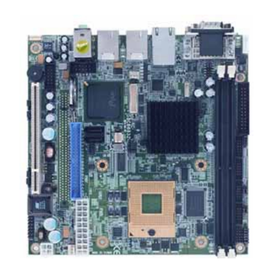
SBC86832 Series All-In-One Mini ITX Board User’s Manual C h a p t e r 2 Jumpers and Connectors Board Layout and Fixing Holes Component Side Jumpers and Connectors... - Page 12 SBC86832 Series All-In-One Mini ITX Board User’s Manual Solder Side Jumpers and Connectors...
-
Page 13: Placement
SBC86832 Series All-In-One Mini ITX Board User’s Manual Placement Component Side Jumpers and Connectors... - Page 14 SBC86832 Series All-In-One Mini ITX Board User’s Manual Solder Side Jumpers and Connectors...
-
Page 15: Jumper Settings
SBC86832 Series All-In-One Mini ITX Board User’s Manual Jumper Settings Proper jumer settings configure the SBC86832 to meet your application purpose. We are herewith listing a summary table of all jumpers and default settings for onboard devices, respectively. Here is a list of jumper settings:... -
Page 16: Com1 Mode Select Jumper
SBC86832 Series All-In-One Mini ITX Board User’s Manual Jumper Default Setting Jumper Setting JP19 USB Voltage Select Short 2-3 JP20 USB Voltage Select Short 1-2 JP21 USB Voltage Select Short 1-2 -- End of Jumper Settings Table -- 2.3.1 COM1 Mode Select Jumper: JP1 These jumpers select the COM1 port’s communication mode to... -
Page 17: Com2~Com4 Mode Select For Type Jumpers
SBC86832 Series All-In-One Mini ITX Board User’s Manual 2.3.4 COM1~COM4 Mode Select for Type Jumpers: JP4, JP5, JP6, JP7 These jumpers select the COM1, COM2, COM3, COM4 ports’ communication mode to operate RS-232 or RS-422/485. COM1 (CN7) COM2 (CN2) Pin 1=12V... -
Page 18: Lvds Voltage Selection Jumper
SBC86832 Series All-In-One Mini ITX Board User’s Manual 2.3.6 LVDS Voltage Selection Jumper: JP11 This jumper is to select the voltage for LVDS interface. JP11 Options Settings 3.3V Short 1-2 (default) Short 2-3 2.3.7 CMOS Clear Jumper: JP14 You may need to use this jumper is to clear the CMOS memory if incorrect settings in the Setup Utility. -
Page 19: Usb Power Select Jumpers
SBC86832 Series All-In-One Mini ITX Board User’s Manual 2.3.11 USB Power Select Jumpers: JP18, JP19, JP20, JP21 JP18, JP19, Options Settings JP20, JP21 5V Standby Short 1-2 Short 2-3 Connectors Connectors connect the CPU card with other parts of the system. -
Page 20: Print Port Or Floppy Connector
SBC86832 Series All-In-One Mini ITX Board User’s Manual Connectors Label ATX Power Connector ATX1 +12V Power Connector ATX2 SMBUS Connector JP13 KB/MS Connector -- End of Connectors Table -- 2.4.1 Print Port or Floppy Connector: CN1 Print Port Connector [Default] This board has a multi-mode parallel port to support: 1. -
Page 21: Com2~Com4 Port Connectors
SBC86832 Series All-In-One Mini ITX Board User’s Manual Floppy Connector [Optional] Signal Signal DRIVE0 INDEX MOTOR ON DSKCHG STEP WDATA WGATE TRK0 RDATA HDSEL DSKCHG 2.4.2 COM2~COM4 Port Connectors: CN2, CN3, CN4 Please refer to the RS-232 pin assignment as listed below:... -
Page 22: Vga & Com1 Connector
SBC86832 Series All-In-One Mini ITX Board User’s Manual Digital I/O Port connector CN5 Pin Assignment Signal Signal Ground (GND) Ground (GND) 2.4.4 VGA & COM1 Connector: CN7 VGA & COM1 connector CN7 Pin Assignment COM1 Description Data Carrier Detect (DCD) -
Page 23: Lvds Backlight Connector
SBC86832 Series All-In-One Mini ITX Board User’s Manual Signal Signal CRT-RED CRT-GREEN CRT-BLUE CRT-HSYNC VGAGND 8 C1 2.4.5 LVDS Backlight Connector: CN8 The 7-pin inverter connector on the SBC is a Hirose connector. It is strongly recommended to use the matching connector Hirose DF13- 7S-1.25C. -
Page 24: Usb*2+Ieee1394 Connectors
SBC86832 Series All-In-One Mini ITX Board User’s Manual LAN Connector Pin Assignment COM1 Description CN9_A MDI0+ MDI0- MDI1+ MDI1- MDI2+ MDI2- MDI3+ MDI3- Active LED 100 LAN LED(Green)/ 1000 LAN LED(Orange) COM1 Description CN9_B MDI0+ MDI0- MDI1+ MDI1- MDI2+ MDI2-... -
Page 25: Lvds Flat Panel Connector
SBC86832 Series All-In-One Mini ITX Board User’s Manual CN10 ,CN13 Signal USB Vcc USB - USB + USB GND 2.4.8 LVDS Flat Panel Connector: CN11 The LVDS connector on the SBC is a 40-pin connector. It is strongly recommended to use the matching connector JST SHDR-40V-S-B. -
Page 26: Sata Connectors
SBC86832 Series All-In-One Mini ITX Board User’s Manual 2.4.9 SATA Connectors: CN14, CN15 These SATA connectors are for high-speed SATA interface ports and they can be connected to hard disk devices. Signal CN14,CN15 SATA_TX+ SATA_TX- SATA_RX- SATA_RX+ 2.4.10 Audio Phone Jack Connector: CN16... -
Page 27: Parallel Ide Connector
SBC86832 Series All-In-One Mini ITX Board User’s Manual USB0 and USB1 Signal Signal CN17, CN19 Ground (GND) Ground (GND) Ground (GND) Ground (GND) 2.4.12 Parallel IDE Connector: CN18 There is a PCI bus enhanced IDE controller that supports master/slave mode and post write transaction mechanisms with 64-byte buffer and master data transaction. -
Page 28: Flat Panel Bezel Connector
SBC86832 Series All-In-One Mini ITX Board User’s Manual 2.4.13 Flat Panel Bezel Connector: CN20 Power LED This 3-pin connector named as Pin 1 and Pin 5 connect the system power LED indicator to such a switch on the case. Pin 1 is assigned as +, and Pin 5 as -. -
Page 29: Internal Audio Connector
SBC86832 Series All-In-One Mini ITX Board User’s Manual 2.4.14 Internal Audio Connector: CN21 Signal CN14, CN15 LINE_OUT_L LINE_OUT_R MIC_IN 2.4. 15 ATX Power Connector: ATX1 Connect the power cable to ATX1 for ATX power supply. Signal Signal ATX1 3.3V 3.3V 3.3V... -
Page 30: Smbus Connector
SBC86832 Series All-In-One Mini ITX Board User’s Manual 2.4.17 SMBUS Connector: JP13 Connector JP13 is for SMBUS interface support. Singnal JP13 CLOCK DATA 2.4.18 Keyboard and PS/2 Mouse Connector: KM1 The board supports a keyboard and Mouse interface. Connector KM1 is a DIN connector for PS/2 keyboard Connection VIA “Y”... -
Page 31: Chapter 3 Hardware Description
C h a p t e r 3 Hardware Description Microprocessors The SBC86832 Series supports Intel Core 2 Duo, Core Duo, Core Solo and Celeron M processors, which make your system operated under Windows 2000/XP and Linux environments. The system performance depends on the microprocessor. -
Page 32: I/O Port Address Map
SBC86832 Series All-In-One Mini ITX Board User’s Manual I/O Port Address Map The Intel® Pentium III/Celeron® M CPUs can communicate via I/O ports. There are total 1KB port addresses available for assignment to other devices via I/O expansion cards. Address... -
Page 33: Interrupt Controller
SBC86832 Series All-In-One Mini ITX Board User’s Manual Interrupt Controller The SBC86832 Series is a 100% PC compatible control board. It consists of 16 interrupt request lines, and four out of them can be programmable. The mapping list of the 16 interrupt request lines is shown as the following table. - Page 34 SBC86832 Series All-In-One Mini ITX Board User’s Manual MEMO Hardware Description...
-
Page 35: Chapter 4 Award Bios Utility
SBC86832 Series All-In-One Mini ITX Board User’s Manual C h a p t e r 4 Award BIOS Utility The Phoenix-Award BIOS provides users with a built-in Setup program to modify basic system configuration. All configured parameters are stored in a battery-backed-up RAM (CMOS RAM) to save the Setup information whenever the power is turned off. -
Page 36: Control Keys
SBC86832 Series All-In-One Mini ITX Board User’s Manual Control Keys Moves cursor to the previous item Up arrow Moves cursor to the next item Down arrow Moves cursor to the item on the left hand Left arrow Move to the item in the right hand... -
Page 37: The Main Menu
SBC86832 Series All-In-One Mini ITX Board User’s Manual The Main Menu Once you enter the Award BIOS CMOS Setup Utility, the Main Menu will appear on the screen. The Main Menu allows you to select from ten setup functions and two exit choices. Use the arrow keys to select the setup function you intend to configure then press <Enter>... -
Page 38: Standard Cmos Setup Menu
SBC86832 Series All-In-One Mini ITX Board User’s Manual Standard CMOS Setup Menu The items in Standard CMOS Setup Menu are divided into 10 categories. Each category includes no, one or more than one setup items. Use the arrow keys to highlight the item and then use the <PgUp>... - Page 39 SBC86832 Series All-In-One Mini ITX Board User’s Manual IDE Primary Master/Primary Slave The categories identify the types of one channel that have been installed in the computer. There are 45 predefined types and 2 users definable types are for Enhanced IDE BIOS. Type 1 to Type 45 is predefined.
- Page 40 SBC86832 Series All-In-One Mini ITX Board User’s Manual Halt On This field determines whether the system will halt if an error is detected during power up. The system boot will halt on any error detected. No errors (default) Whenever the BIOS detect a non-fatal error, the All errors system will stop and you will be prompted.
-
Page 41: Advanced Bios Features
SBC86832 Series All-In-One Mini ITX Board User’s Manual Advanced BIOS Features This section allows you to configure and improve your system and allows you to set up some system features according to your preference. CPU Feature Scroll to this item and press <Enter> to view the CPU Feature sub menu. - Page 42 SBC86832 Series All-In-One Mini ITX Board User’s Manual Hard Disk Boot Priority Scroll to this item and press <Enter> to view the sub menu to decide the disk boot priority. Press <Esc> to return to the Advanced BIOS Features page.
- Page 43 SBC86832 Series All-In-One Mini ITX Board User’s Manual First/Second/Third Boot Device These items allow the selection of the 1 , and 3 devices that the system will search for during its boot-up sequence. The wide range of selection includes Floppy, LS120, ZIP100, HDD0~3, SCSI, and CDROM.
- Page 44 SBC86832 Series All-In-One Mini ITX Board User’s Manual Typematic Rate Setting This determines the typematic rate of the keyboard. The default value is “Disabled”. Enable typematic rate and typematic delay Enabled programming Disable typematic rate and typematic delay Disabled programming. The system BIOS will use default value of these 2 items and the default is controlled by keyboard.
-
Page 45: Advanced Chipset Features
SBC86832 Series All-In-One Mini ITX Board User’s Manual NOTE: To disable security, select PASSWORD SETTING at Main Menu and then you will be asked to enter password. Do not type anything, just press <Enter> and it will disable security. Once the security is disabled, the system will boot and you can enter Setup freely. - Page 46 SBC86832 Series All-In-One Mini ITX Board User’s Manual to the cooling of memory. CAS Latency Time You can select CAS latency time in HCLKs 2, 3, or Auto. The board designer should set the values in this field, depending on the DRAM installed.
-
Page 47: Integrated Peripherals
SBC86832 Series All-In-One Mini ITX Board User’s Manual Integrated Peripherals This section allows you to configure your SuperIO Device, IDE Function and Onboard Device. OnChip IDE Device Scroll to this item and press <Enter> to view the sub menu OnChip IDE Device. - Page 48 SBC86832 Series All-In-One Mini ITX Board User’s Manual block read/writes per sector the drive can support. IDE DMA transfer access Automatic data transfer between system memory and IDE device with minimum CPU intervention. This improves data throughput and frees CPU to perform other tasks.
- Page 49 SBC86832 Series All-In-One Mini ITX Board User’s Manual Onboard Device Scroll to this item and press <Enter> to view the sub menu Onboard Device. USB Controller Enable this item if you are using the USB in the system. You should disable this item if a higher-level controller is added.
- Page 50 SBC86832 Series All-In-One Mini ITX Board User’s Manual Super IO Device Scroll to this item and press <Enter> to view the sub menu Super IO Device. Onboard FDC Controller Select Enabled if your system has a floppy disk controller (FDC) installed on the system board and you wish to use it.
-
Page 51: Power Management Setup
SBC86832 Series All-In-One Mini ITX Board User’s Manual ECP mode. PWRON After PWR-Fail This item enables your computer to automatically restart or return to its operating status. Press <Esc> to return to the Integrated Peripherals page. Power Management Setup The Power Management Setup allows you to save energy of your system effectively. - Page 52 SBC86832 Series All-In-One Mini ITX Board User’s Manual the information of system configuration and open applications/files is saved to main memory that remains powered while most other hardware components turn off to save energy. The information stored in memory will be used to restore the system when a “wake up”...
- Page 53 SBC86832 Series All-In-One Mini ITX Board User’s Manual This option follows the conventional manner systems perform when power is turned OFF. Instant-Off is a soft Instant-Off power OFF sequence requiring only the switching of the power supply button to OFF...
-
Page 54: Pnp/Pci Configuration Setup
SBC86832 Series All-In-One Mini ITX Board User’s Manual 4.10 PnP/PCI Configuration Setup This section describes configuring the PCI bus system. PCI, or Personal Computer Interconnect, is a system which allows I/O devices to operate at speeds nearing the speed the CPU itself uses when communicating with its own special components. -
Page 55: Pc Health Status
SBC86832 Series All-In-One Mini ITX Board User’s Manual interrupt: 1. Legacy ISA Devices compliant with the original PC AT bus specification, requiring a specific interrupt (such as IRQ4 for serial port 2. PCI/ISA PnP Devices compliant with the Plug and Play standard, whether designed for PCI or ISA bus architecture. -
Page 56: Frequency/Voltage Control
SBC86832 Series All-In-One Mini ITX Board User’s Manual 4.12 Frequency/Voltage Control This section is to control the CPU frequency and Supply Voltage, DIMM OverVoltage and AGP voltage. Auto Detect PCI Clk The enabled item can automatically disable the clock source for a PCI slot which does not have a module in it, reducing EMI (ElectroMagnetic Interference). -
Page 57: Load Optimized Defaults
SBC86832 Series All-In-One Mini ITX Board User’s Manual 4.13 Load Optimized Defaults This option allows you to load the default values to your system configuration. These default settings are optimal and enable all high performance features. To load SETUP defaults value to CMOS SRAM, enter “Y”. If not, enter “N”. -
Page 58: Set Supervisor/User Password
SBC86832 Series All-In-One Mini ITX Board User’s Manual 4.14 Set Supervisor/User Password You can set either supervisor or user password, or both of then. The differences between are: Supervisor password: can enter and change the options of the setup menus. -
Page 59: Save & Exit Setup
SBC86832 Series All-In-One Mini ITX Board User’s Manual 4.15 Save & Exit Setup This allows you to determine whether or not to accept the modifications. Typing “Y” quits the setup utility and saves all changes into the CMOS memory. Typing “N” brigs you back to Setup utility. -
Page 60: Exit Without Saving
SBC86832 Series All-In-One Mini ITX Board User’s Manual 4.16 Exit Without Saving Select this option to exit the Setup utility without saving the changes you have made in this session. Typing “Y” will quit the Setup utility without saving the modifications. Typing “N” will return you to Setup utility. - Page 61 SBC86832 Series All-In-One Mini ITX Board User’s Manual Award BIOS Utility...
-
Page 62: Appendix A
SBC86832 Series All-In-One Mini ITX Board User’s Manual A p p e n d i x A Watchdog Timer Watchdog Timer Setting After the system stops working for a while, it can be auto-reset by the Watchdog Timer. The integrated Watchdog Timer can be set up in the system reset mode by program. - Page 63 SBC86832 Series All-In-One Mini ITX Board User’s Manual ; IF to disable WDT: O 2E 30 O 2F 00 ; Can be disable at any time Timeout Value Range 1 to 255 Minute / Second Program Sample Watchdog Timer can be set to system reset after 5-second timeout.
-
Page 64: Appendix B
SBC86832 Series All-In-One Mini ITX Board User’s Manual A p p e n d i x B Digital I/O Digital I/O Software Programming GPI program sample: O 2E 87 O 2E 87 O 2E 2A Setting GP10~GP17 O 2F FF... - Page 65 SBC86832 Series All-In-One Mini ITX Board User’s Manual GPO program sample: o 2e 87 o 2e 87 o 2e 2A o 2f FF Setting GP10~GP17 o 2e 07 o 2f 07 Select Device 7 o 2e 30 o 2f 01...
Need help?
Do you have a question about the SBC86832 Series and is the answer not in the manual?
Questions and answers