Sony DCR-PC6E Service Manual
Hide thumbs
Also See for DCR-PC6E:
- Operating instructions manual (256 pages) ,
- Service manual (25 pages)
Table of Contents
Advertisement
DCR-PC6E/PC9/PC9E
SERVICE MANUAL
SERVICE MANUAL
Ver 1.0 2001. 05
Level 2
On the VC-265/265A board
This service manual provides the information that is premised the
circuit board replacement service and not intended repair inside the
VC-265/265A board.
Therefore, schematic diagram, printed wiring board, waveforms, parts
location and electrical parts list of the VC-265/265A board are not shown.
The following pages are not shown.
Printed wiring board ......................... Pages 4-15 to 4-18
Schematic diagram .......................... Pages 4-19 to 4-54
Waveforms and parts location ......... Pages 4-74 to 4-77
Electrical parts list ............................ Pages 6-13 to 6-24
Video camera
recorder
System
Video recording system
2 rotary heads
Helical scanning system
Audio recording system
Rotary heads, PCM system
Quantization: 12 bits (Fs 32 kHz,
stereo 1, stereo 2), 16 bits
(Fs 48 kHz, stereo)
Video signal
DCR-PC9:
NTSC color, EIA standards
DCR-PC6E/PC9E:
PAL colour, CCIR standards
Usable cassette
Mini DV cassette with the
mark printed
Tape speed
SP: Approx. 18.81 mm/s
LP: Approx. 12.56 mm/s
Recording/playback time
(using cassette DVM60)
SP: 1 hour
LP: 1.5 hours
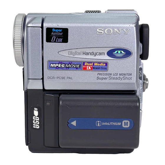
Photo : DCR-PC9E
RMT-814
SPECIFICATIONS
Fastforward/rewind time
(using cassette DVM60)
Approx. 2 min. and 30 seconds
Viewfinder
Electric viewfinder (colour)
Total dot number:
DCR-PC9/PC9E: 180 000 (800 × 225)
DCR-PC6E: 113 578 (521 × 218)
Image device
4.5 mm (1/4 type) CCD
(Charge Coupled Device)
DCR-PC9:
Approx. 680 000 pixels
(Effective: 340 000 pixels)
DCR-PC6E/PC9E:
Approx. 800 000 pixels
(Effective: 400 000 pixels)
Lens
Carl Zeiss
Combined power zoom lens
Filter diameter 30 mm. (1 3/16 in.)
10× (Optical), 120× (Digital)
Focal length
3.3 - 33 mm (5/32 - 1 5/16 in.)
When converted to a 35 mm still
camera 42 - 420 mm (1 11/16 - 16 5/
8 in.)
DIGITAL VIDEO CAMERA RECORDER
Hong Kong Model
For MECHANISM ADJUSTMENTS, refer to the
"DV MECHANICAL ADJUSTMENT MANUAL
J MECHANISM " (9-929-807-11).
NTSC model : DCR-PC9
PAL model
: DCR-PC6E/PC9E
Colour temperature
Auto, HOLD (Hold),
Indoor
(3 200K),
Outdoor (5 800K)
Minimum illumination
5 lx (lux) (F 1.7)
0 lx (lux) (in the NightShot mode)*
* Objects unable to be seen due to
the dark can be shot with infrared
lighting.
Input/Output connectors
S video input/output (DCR-PC9/
PC9E)
S video output (DCR-PC6E)
4-pin mini DIN
Luminance signal: 1 Vp-p,
75 Ω (ohms), unbalanced, sync
negative
Chrominance signal:
DCR-PC9: 0.286 Vp-p,
DCR-PC6E/PC9E: 0.3 Vp-p
75 Ω (ohms), unbalanced
Audio/Video input/output (DCR-
PC9/PC9E)
RMT-814
US Model
Canadian Model
Korea Model
DCR-PC9
AEP Model
UK Model
DCR-PC6E/PC9E
E Model
Tourist Model
DCR-PC9/PC9E
Australian Model
Chinese Model
DCR-PC9E
J MECHANISM
Audio/video output (DCR-PC6E)
AV MINI JACK, input/output auto
switch
Video signal: 1 Vp-p, 75 Ω (ohms),
unbalanced, sync negative
Audio signal: 327 mV, (at output
impedance more than 47 kΩ
(kilohms) )
Input impedance with more than
47 kΩ (kilohms)
Output impedance with less than
2.2 kΩ (kilohms)
DV input/output (DCR-PC9/PC9E)
DV output (DCR-PC6E)
4-pin connector
Headphone jack
Stereo minijack (ø 3.5 mm)
LANC
jack
Stereo mini-minijack (ø 2.5 mm)
USB jack (DCR-PC9/PC9E only)
mini-B
— Continued on next page —
Advertisement
Table of Contents

Related Manuals for Sony DCR-PC6E


Summary of Contents for Sony DCR-PC6E
- Page 1 DCR-PC9/PC9E: 180 000 (800 × 225) * Objects unable to be seen due to impedance more than 47 kΩ 2 rotary heads DCR-PC6E: 113 578 (521 × 218) the dark can be shot with infrared (kilohms) ) Helical scanning system Image device lighting.
- Page 2 MARK 0 ON THE SCHEMATIC DIAGRAMS AND IN THE PARTS CRITIQUES POUR LA SÉCURITÉ DE FONCTIONNEMENT. NE LIST ARE CRITICAL TO SAFE OPERATION. REPLACE THESE REMPLACER CES COMPOSANTS QUE PAR DES PIÈSES SONY COMPONENTS WITH SONY PARTS WHOSE PART NUMBERS DONT LES NUMÉROS SONT DONNÉS DANS CE MANUEL OU APPEAR AS SHOWN IN THIS MANUAL OR IN SUPPLEMENTS DANS LES SUPPÉMENTS PUBLIÉS PAR SONY.
- Page 3 2-pin adaptor (1) 6 “Memory Stick” (1) DCR-PC9: JE/PC9E: JE only DCR-PC9/PC9E only qf 2-pin adaptor (1) 7 A/V connecting cable (1) DCR-PC9: E,HK/PC9E: E,HK only Table for difference of functions Model DCR-PC6E DCR-PC9 DCR-PC9E Remark AEP,UK US,CND,E, AEP,UK,E,HK, Destination HK,KR,JE...
-
Page 4: Table Of Contents
Searching the boundaries of recorded tape by title BLOCK DIAGRAMS – Title search ····································································· 1-21 3-1. OVERALL BLOCK DIAGRAM (1/3)(DCR-PC6E) ······ 3-1 Searching a recording by date – Date search ······················· 1-21 3-2. OVERALL BLOCK DIAGRAM (1/3)(DCR-PC9/PC9E) · 3-3 Searching for a photo – Photo search/Photo scan ················ 1-22 3-3. - Page 5 PRINTED WIRING BOARDS AND Initializing the C, D, 8 Page Data ···································· 5-8 Modification of C, D, 8 Page Data ·································· 5-8 SCHEMATIC DIAGRAMS C Page Table ···································································· 5-8 4-1. FRAME SCHEMATIC DIAGRAM (1/2) ······················· 4-1 D Page Table ·································································· 5-10 FRAME SCHEMATIC DIAGRAM (2/2) ·······················...
- Page 6 3-2. SYSTEM CONTROL SYSTEM ADJUSTMENT ········ 5-40 Initialization of B, C, D, E, F, 7, 8 Page Data ··············· 5-40 Serial No. Input ····························································· 5-40 2-1. Company ID Input ························································· 5-40 2-2. Serial No. Input ····························································· 5-40 Touch Panel Adjustment (VC-265 board) ····················· 5-42 Battery End Check (VC-265 board) ······························...
-
Page 7: Service Note
SERVICE NOTE POWER SUPPLY DURING REPAIRS In this unit, about 10 seconds after power is supplied to the battery terminal using the regulated power supply (8.4V), the power is shut off so that the unit cannot operate. These following two methods are available to prevent this. Take note of which to use during repairs. Method 1. -
Page 8: Self-Diagnosis Function
SELF-DIAGNOSIS FUNCTION SELF-DIAGNOSIS FUNCTION SELF-DIAGNOSIS DISPLAY When problems occur while the unit is operating, the self-diagnosis When problems occur while the unit is operating, the counter of the function starts working, and displays on the viewfinder or LCD viewfinder or LCD screen consists of an alphabet and 4-digit screen what to do. -
Page 9: Self-Diagnosis Code Table
SELF-DIAGNOSIS CODE TABLE Self-diagnosis Code Block Detailed Symptom/State Correction Function Code Non-standard battery is used. Use the info LITHIUM battery. Condensation. Remove the cassette, and insert it again after one hour. Video head is dirty. Clean with the optional cleaning cassette. LOAD direction. -
Page 10: General
Connect the plug with its v mark facing the Holding Grip. Set the POWER switch to VCR (DCR- Press of the touch panel to PC9E)/PLAYER (DCR-PC6E) while rewind the tape. Inserting a cassette (p. 27) pressing the small green button. POWER... -
Page 11: Getting Started
— Getting started — Using this manual Using this manual Note on Cassette Memory The instructions in this manual are for the two Your camcorder is based on the DV format. You models listed in the table below. Before you start can only use mini DV cassettes with your reading this manual and operating your camcorder. -
Page 12: Step 1 Preparing The Power Supply
NP-FM91 any trouble occurs with this unit, disconnect the plug from a wall socket as soon as possible to cut При использовании сетевого адаптера DCR-PC6E off the power. Расположите сетевой адаптер переменного тока возле штепсельной розетки. В случае Recording with the viewfinder/ Recording with the LCD screen/ каких-либо... -
Page 13: Connecting To A Wall Socket
(прилагается) series battery packs have the mark. совместимой электронной аппаратурой. Это NP-FM50 SERIES устройство совместимо с батарейным блоком “InfoLITHIUM” is a trademark of Sony NP-FM70 “InfoLITHIUM” (cерии M). Ваша видеокамера Corporation. NP-FM90 работает только с батарейным блоком NP-FM91 “InfoLITHIUM”. На батарейных блоках... -
Page 14: Step 2 Setting The Date And Time
VCR (DCR- •Do not press the LCD screen too hard. PC9E)/PLAYER (DCR-PC6E) (in the playback •Do not touch the LCD screen with wet hands. mode) while pressing the small green button. •If FN is not on the LCD screen, touch the LCD (4) Press FN. -
Page 15: Recording - Basics
— Recording – Basics — Recording a picture Recording a picture After recording Your camcorder automatically focuses for you. (1) Set the POWER switch to OFF (CHARGE). (1) Remove the lens cap and pull the lens cap (2) Close the LCD panel and set the Holding Grip string to fix it. - Page 16 The subject uses this feature to check his or her mode, press FN and select PAGE2. own image on the LCD screen while you look at In VCR (DCR-PC9E)/PLAYER (DCR-PC6E) the subject in the viewfinder. mode, press FN to display PAGE1 (p. 29).
-
Page 17: Shooting Backlit Subjects - Back Light
CAMERA mode and “0:00:00:00” the power zoom lever toward the “T” side. (hours : minutes : seconds : frames) in VCR (DCR-PC9E)/PLAYER (DCR-PC6E) mode. You When the POWER switch is set to MEMORY (DCR-PC9E only) cannot rewrite only the time code. -
Page 18: Self-Timer Recording
The self-timer recording mode is automatically cancelled when: – The self-timer recording is finished. – The POWER switch is set to OFF (CHARGE) or VCR (DCR-PC9E)/PLAYER (DCR-PC6E). When the POWER switch is set to MEMORY (DCR-PC9E only) You can also record still images on “Memory Stick”s with the self-timer. -
Page 19: Playback - Basics
(2) Press OPEN to open the LCD panel. back to the camcorder body with the LCD screen (3) Set the POWER switch to VCR (DCR-PC9E)/ facing out. PLAYER (DCR-PC6E) while pressing the small green button. (4) Press to rewind the tape. -
Page 20: Viewing The Recording On Tv
DV TV screen. You can operate the playback control (DCR-PC9E)/DV OUT (DCR-PC6E) jack. buttons in the same way as when you monitor playback pictures on the LCD screen. When... -
Page 21: Advanced Recording Operations Recording A Still Image On A Tape - Tape Photo Recording
You cannot cancel the self-timer recording using the Remote Commander. Note The self-timer recording mode is automatically cancelled when: – The self-timer recording is finished. – The POWER switch is set to OFF (CHARGE) or VCR (DCR-PC9E)/PLAYER (DCR-PC6E). 1-12... -
Page 22: Using The Wide Mode
Recording a still image on a tape – Tape Photo recording Using the wide mode Printing the still image You can record a 16:9 wide picture to watch on You can print a still image by using the video the 16:9 wide-screen TV (16:9WIDE). printer (optional). -
Page 23: Using Special Effects - Picture Effect
Using special effects Using the fader function – Picture effect Note You cannot use the following functions while You can digitally process images to obtain special using the fader function. Also, you cannot use effects like those in films or on the TV. the fader function while using the following functions. -
Page 24: Using The Program Ae Function
Using special effects Using special effects – Digital effect – Digital effect (1) In CAMERA mode, press FN to display Notes PAGE1. •The following functions do not work during (2) Press DIG EFFT. The screen to select a desired digital effect: digital effect mode appears. -
Page 25: Adjusting The White Balance Manually
Adjusting the white balance manually Using the PROGRAM AE function •The following functions do not work in the low You can manually adjust and set the white lux mode: balance. This adjustment makes white subjects – Digital effect look white and allows more natural colour –... -
Page 26: Using The Spot Light-Metering Mode - Flexible Spot Meter
Using the spot light- Using the spot light-metering metering mode mode – Flexible Spot Meter – Flexible Spot Meter Note When the Flexible Spot Meter mode is in use, the You can take a picture with the appropriate backlight function does not work. exposure automatically for just the point you want to focus on and with its exposure fixed. -
Page 27: Interval Recording
To create – Set the POWER switch to OFF (CHARGE), VCR this effect, alternately move the subject a little (DCR-PC9E)/PLAYER (DCR-PC6E) or and make a cut recording. We recommend that MEMORY (DCR-PC9E only). you use a tripod, and operate the camcorder using the Remote Commander after step 4. -
Page 28: Using The Viewfinder
You can operate with the touch such as pens. panel using the viewfinder. •In VCR (DCR-PC9E)/PLAYER (DCR-PC6E) or Use the viewfinder in the following case: memory playback mode (DCR-PC9E only), you When operating camera brightness and the fader... -
Page 29: Enlarging Images Recorded On Tapes - Tape Pb Zoom
The area you pressed moves to the centre of are not output through the DV (DCR-PC9E)/ the screen, and the playback image is DV OUT (DCR-PC6E) jack. enlarged at twice the size. If you press the •You cannot use the PB ZOOM function for other area again, the area moves to the centre pictures processed by the digital effect function. -
Page 30: Searching The Boundaries Of Recorded Tape By Title
(p. 134). (The default setting is ON.) To superimpose a title (1) Set the POWER switch to VCR (DCR-PC9E)/ See page 125. PLAYER (DCR-PC6E). (2) Press SEARCH MODE on the Remote Commander repeatedly, until the TITLE SEARCH indicator appears. -
Page 31: Searching For A Photo - Photo Search/Photo Scan
Searching for a photo by using using cassette memory cassette memory (1) Set the POWER switch to VCR (DCR-PC9E)/ PLAYER (DCR-PC6E). Before operation (2) Press FN to display PAGE1. •You can use this function only when playing (3) Press MENU, then set CM SEARCH to OFF in back a tape with cassette memory. -
Page 32: Dubbing Only Desired Scenes - Digital Program Editing
VHS, cable) (optional) to DV (DCR-PC9E)/DV OUT S-VHS, VHSC, S-VHSC, (DCR-PC6E) of your camcorder and to DV IN of Betamax, mini DV or the DV products. With digital-to-digital connection, video and audio signals are If your VCR is a monaural type... - Page 33 Notes 1 Set the POWER switch to VCR (DCR-PC9E)/ •You cannot dub the titles, display indicators, or PLAYER (DCR-PC6E) on your camcorder. the contents of cassette memory. 2 Turn the power of the connected VCR on, •When you connect with an i.LINK cable (DV then set the input selector to LINE.
- Page 34 VCR flashes on the LCD screen. (1) Set the POWER switch to VCR (DCR-PC9E)/ When finished, the indicator changes to PLAYER (DCR-PC6E) on your camcorder. COMPLETE. (2) Turn the power of the connected VCR on, then set the input selector to DV input.
-
Page 35: Using With An Analog Video Unit And Your Computer - Signal Convert Function (Dcr-Pc9E Only)
Dubbing only desired scenes Dubbing only desired scenes – Digital program editing – Digital program editing Erasing the programme you have set Operation 1: Making the Erase OUT mark first, and then IN mark of the Programme last programme. (1) Insert the tape for playback into your (1) Press UNDO. -
Page 36: Recording Video Or Tv Programmes (Dcr-Pc9E Only)
Using with an analog video unit Recording video or TV and your computer – Signal programmes convert function After capturing images and sound – DCR-PC9E only Stop capturing procedures on your computer, Using the A/V connecting cable and stop the playback on the analog video unit. You can record a tape from another VCR or a TV programme from a TV that has video/audio Notes... -
Page 37: Inserting A Scene From A Vcr - Insert Editing
Inserting a scene from Recording video or TV a VCR – Insert Editing programmes When you have finished dubbing a – DCR-PC9E only tape You can insert a new scene from a VCR onto your originally recorded tape by specifying the Press x on both your camcorder and the VCR. -
Page 38: Superimposing A Title
AUDIO MIX returns to the original sound (ST1) only. The default setting is original sound only. (1) In CAMERA or VCR (DCR-PC9E)/PLAYER (DCR-PC6E) mode, press FN and select Notes PAGE2. •New sound cannot be recorded on a tape (2) Press TITLE. -
Page 39: Making Your Own Titles
Each title can have up to 20 characters. (1) Set the POWER switch to CAMERA or VCR (DCR-PC9E)/PLAYER (DCR-PC6E). (1) Set the POWER switch to CAMERA or VCR (2) Press FN to display PAGE1. (DCR-PC9E)/PLAYER (DCR-PC6E). -
Page 40: Labelling A Cassette
In step 5, select CUSTOM1 SET or CUSTOM2 switch to CAMERA or VCR (DCR-PC9E)/ SET, depending on which title you want to PLAYER (DCR-PC6E), the label is change, then press EXEC and then enter the new displayed for about 5 seconds. -
Page 41: Customizing Your Camcorder
CAMERA SET VCR SET (DCR-PC9E) (1) In CAMERA, VCR(DCR-PC9E)/PLAYER PLAYER SET (DCR-PC6E) (DCR-PC6E) or MEMORY (DCR-PC9E only) LCD/VF SET mode, press FN to display PAGE1. (2) Press MENU to display the menu. MEMORY SET (DCR-PC9E only) (3) Press r/R to select a desired icon, and press CM SET EXEC. -
Page 42: Memory Stick" Operations (Dcr-Pc9E Only)
•“Memory Stick” supplied with your camcorder has been formatted at factory. Formatting with your •When you record in the LP mode, we recommend using a Sony Excellence/Master mini DV cassette camcorder is not required. so that you can get the most out of your camcorder. - Page 43 – If you remove the “Memory Stick”, turn the power off or detach the battery for Sony Corporation. replacement when the access lamp is flashing. – If you use “Memory Stick”s near magnets or •Windows and Windows Media are either...
- Page 44 Using a “Memory Stick” Using a “Memory Stick” – introduction – introduction Notes •When using the touch panel, press operation LOCK POWER LOCK buttons with your thumb supporting the LCD screen from the back side of it or press those buttons lightly with your index finger.
-
Page 45: Recording Still Images On "Memory Stick
Using a “Memory Stick” Using a “Memory Stick” – introduction – introduction Image size settings/ Selecting the size of a moving picture Setting/ Meaning/ Indicator/ Recording/ Playback/ You can select 320 × 240 or 160 × 112 of the moving picture size. The default setting is 320 × ×... - Page 46 Recording still images on Recording still images on “Memory Stick” “Memory Stick” – Memory photo recording – Memory photo recording (1) Set the POWER switch to MEMORY. Make When the POWER switch is set to MEMORY sure that the LOCK is set to the right (unlock) The following functions do not work: position.
-
Page 47: Recording An Image From A Tape As A Still Image
Recording an image Recording an image from a tape from a tape as a still as a still image image When the access lamp is lit or flashing Do not shake or strike the unit. As well do not – DCR-PC9E only turn the power off , eject a “Memory Stick”... -
Page 48: Recording Moving Pictures On "Memory Stick"S
Recording moving pictures on Recording moving pictures “Memory Stick”s – MPEG movie on “Memory Stick”s recording – MPEG movie recording Note Sound is recorded in monaural. – DCR-PC9E only You can record moving pictures with sound on When the POWER switch is set to MEMORY “Memory Stick”s. -
Page 49: Superimposing A Still Image In A "Memory Stick" On A Moving Picture - Memory Mix
Recording a picture from a tape Recording a picture from a tape as a moving picture as a moving picture Using the i.LINK cable (DV connecting Recording a moving picture cable) from other equipment Before operation •Set DISPLAY to LCD in the menu settings. (p. - Page 50 Superimposing a still image in a Superimposing a still image in a “Memory Stick” on a moving “Memory Stick” on a moving picture – MEMORY MIX picture – MEMORY MIX Items to adjust Recording a superimposed M. CHROM The colour (blue) scheme of the image to tape area in the still image which is to be swapped with a moving...
-
Page 51: Copying Still Images From A Tape - Photo Save
Superimposing a still image in a Copying still images “Memory Stick” on a moving from a tape – Photo picture – MEMORY MIX save Notes •You cannot use MEMORY MIX function for – DCR-PC9E only moving pictures recorded on “Memory Stick”s. Using the search function, you can automatically •When the overlapping still image has a large take in only still images from tapes and record... -
Page 52: Viewing A Moving Picture - Mpeg Movie Playback
Viewing a still image Viewing a still image – Memory photo playback – Memory photo playback To play back recorded images on a TV screen Playing back 6 recorded images •Connect your camcorder to the TV with the at a time (index screen) A/V connecting cable supplied with your camcorder before the operation. -
Page 53: Viewing Images Using Your Computer
“System,”, and click “Device Manager”. complete without interrupting it. 5 Select “Other devices”. Select the device prefixed with the “?” mark and delete. Ex: (?)Sony Handycam 6 Turn the power OFF (CHARGE), and then disconnect the USB cable. USB jack/ 7 Reboot your computer. - Page 54 3 to the System Folder icon in (Example: “Removable Disk (E:)”) the window opened in step 4 (drag and drop). The folders inside the “Memory Stick” are •Sony Camcorder USB Driver displayed. •Sony Camcorder USB Shim (6) Select and double-click the desired image file (6) When “Put these items into the Extensions...
-
Page 55: Playing Back Images Continuously - Slide Show
Enlarging still images recorded Enlarging still images on “Memory Stick”s – Memory PB recorded on “Memory ZOOM Stick”s – Memory PB ZOOM Note You cannot record images in the “Memory – DCR-PC9E only Stick” enlarged by the Memory PB ZOOM You can enlarge still images recorded on a mode. -
Page 56: Preventing Accidental Erasure
Preventing accidental erasure Deleting images – Image protection – DCR-PC9E only You can delete images stored in a “Memory – DCR-PC9E only Stick”. You can delete all images or selected To prevent accidental erasure of important images. images, you can protect selected images. Deleting selected images Before operation Insert a “Memory Stick”... -
Page 57: Writing A Print Mark - Print Mark
An unknown picture is displayed on the screen. problem. If the problem persists, disconnect the power source and contact your Sony dealer. If CAMERA or DEMO MODE is set to ON in the menu settings without a cassette inserted, your camcorder automatically “C:ss:ss”... - Page 58 • The camcorder is connected to DV equipment of other than • The write-protect tab on the “Memory Stick” is set to LOCK. Sony using the i.LINK cable (DV connecting cable). Deleting all the images cannot be c Release the lock (p. 148).
-
Page 59: Self-Diagnosis Display
• The battery pack is not properly installed. authorized Sony facility. c Install it properly (P. 18). CHARGE lamp flashes. • Something is wrong with the battery pack. c Please contact your Sony dealer or local authorized Sony Five-digit display Cause and/or Corrective Actions service facility. C:04:ss •... -
Page 60: Additional Information
– you have played back the tape in VCR (DCR- in stereo 1, and the new sound in stereo 2 in 32 PC9E)/PLAYER (DCR-PC6E) mode. kHz. The balance between stereo 1 and stereo 2 If there is a blank portion or discontinuous... -
Page 61: About I.link
About the “InfoLITHIUM” battery About i.LINK pack Remaining battery time indicator The DV (DCR-PC9E) or DV OUT (DCR-PC6E) jack on this unit is an i.LINK-compliant DV OUT •If the power may go off although the remaining battery time indicator indicates that the battery (DCR-PC6E) or DV IN/OUT (DCR-PC9E) jack. -
Page 62: Maintenance Information And Precautions
If the above problem, [a], [b] or [c] occurs, clean the video heads for 10 seconds with the Sony If moisture condensation occurred DVM-12CLD cleaning cassette (optional). Check [a] [b]... - Page 63 •Clean the camcorder body with a dry soft cloth, checked by a Sony dealer before operating it or a soft cloth lightly moistened with a mild any further.
-
Page 64: Quick Reference
Your camcorder is equipped with a Carl Zeiss lens which can reproduce a fine image. The lens for your camcorder was developed jointly by Carl Zeiss, in Germany, and Sony Fastening the grip strap Corporation. It adopts the MTF* measurement system for video camera and offers a quality as the Carl Zeiss lens. - Page 65 VTR 2. Commander modes 1, 2 and 3 are used to distinguish your camcorder from other Sony VCRs to avoid remote control misoperation. If you use another Sony VCR in the Commander 1 Cassette memory indicator (p. 226) mode VTR 2, we recommend changing the commander mode or covering the sensor of the 2 Remaining battery time indicator (p.
- Page 66 Identifying the parts and controls qf Self-timer indicator (p. 43, 162) qg STBY/REC indicator (p. 30)/Video control mode indicator (p. 50)/Picture size indicator (DCR-PC9E only) (p. 156)/Image quality mode indicator (DCR-PC9E only) (p. 154) qh NIGHTSHOT indicator (p. 41) qj Warning indicators (p. 214) qk Tape counter indicator (p.
-
Page 67: Disassembly
DCR-PC6E/PC9/PC9E SECTION 2 DISASSEMBLY The following flow chart shows the disassembly procedure. 2-1. LCD section (PD-148/148A board) PD-148/148A board service position 2-2. Cabinet (R) section 2-3. Lens-EVF section 2-4. VC-265/265A board 2-5. Mechanism deck 2-6. Cabinet (G) assembly 2-7. Memory stick connector, FP-347 flexible board 2-8. -
Page 68: Lcd Section (Pd-148/148A Board)
NOTE: Follow the disassembly procedure in the numerical order given. 2-1. LCD SECTION (PD-148/148A BOARD) 1 Two screws (M1.7 × 2.5) 3 LCD cabinet (R) assembly 2 Two claws 5 Two screws (M1.7 × 2.5) qa Liquid crystal indicator module qs PD-148 board (PC9/PC9E), PD-148A board (PC6E) Inverter transformer unit,... -
Page 69: Cabinet (R) Section
2-2. CABINET (R) SECTION 1 Two plate screws (M2), lock ace 2 Accessory shoe 4 Microphone cover 3 Two claws 6 Screw (M1.7 × 4), lock ace, p2 5 Screw (M1.7 × 4), lock ace, p2 7 Four screws (M1.7 × 2.5) 8 Two screws (M1.7 ×... -
Page 70: Vc-265/265A Board
2-4. VC-265/265A BOARD Flexible board (from video head) (10P) Flexible board (from drum motor) (10P) 5 FP-102 flexible board (27P) 1 Control switch block Flexible board (FK-1770) (51P) (from capstan motor) (27P) 2 FP-347 flexible board (9P) (PC9/PC9E) 8 VC-265 board (PC9/PC9E) VC-265A board (PC6E) 4 Three screws (M1.7 ×... -
Page 71: Cabinet (G) Assembly
2-6. CABINET (G) ASSEMBLY 1 Two tapping screws (M1.7 × 4) 2 Four tapping screws (M1.7 × 4) 1 Screw (M1.7 × 2.5) 3 Two screws 5 Sleeve (rear) (M1.7 × 2.5) 2 Special head (step) 4 Hold grip assembly screw (M2.6) 3 Sleeve (front) 2 Cabinet (G) assembly... -
Page 72: Control Switch Block (Fk-1770)
2-8. CONTROL SWITCH BLOCK (FK-1770) 1 Two screws (M1.7 × 2.5) 1 Two screws (M1.7 × 2.5) 4 Shoe frame 3 Two tapping screws (M1.7 × 4) 2 Screw (M1.7 × 2.5) 6 Cabinet (L) 2 Two tapping screws (M1.7 × 4) 7 Control switch block (FK-1770) 5 Tapping... -
Page 73: Board
2-10.BJ-002/002A BOARD 8 Screw (M1.7 × 4), (Note 1) qa Battery terminal board 7 Screw (M1.7 × 2.5) lock ace, p2 qf BJ-002 board (PC9/PC9E) BJ-002A board (PC6E) (Note 1) qd Two tapping qs DC-IN 5 PD-113 harness (16P) screws (M1.7 × 4) connector (Note 1) 6 PR-063 harness (8P) - Page 74 [SERVICE POSITION TO CHECK THE CAMERA SECTION] Connection to Check the Camera Section To check the camera section, set the camera to the “Forced camera power ON” mode. (Or, connect the control switch block (PS-1770) to the control switch block (FK-1770) and set the power switch to the “CAMERA” position.) Operate the camera functions of the zoom and focus using the adjustment remote commander (with the HOLD switch set in the OFF position).
-
Page 75: Lcd Hinge Assembly, Pr-037, Po-007 Boards
2-11.LCD HINGE ASSEMBLY, PR-037, PO-007 BOARDS (Remove the LCD unit referring to section 2-1 before starting disassembling.) 6 Hinge cover (rear) 4 Screw (M1.7 × 2.5) 5 Two claws 3 Blind plate assembly, PO-007 board 7 Claw 1 Screw (M1.7 × 2.5) 8 Hinge cover (front) 2 Tapping screw... -
Page 76: Circuit Boards Location
2-12.CIRCUIT BOARDS LOCATION CF-085 (CCD IMAGER, PITCH/YAW SENSOR) NS-013 REMOTE COMMANDER RECEIVER INVERTER TRANSFORMER UNIT PD-148 (PC9/PC9E) PD-148A (PC6E) VC-265 (PC9/PC9E) (LCD DRIVE, BACK LIGHT) VC-265A (PC6E) CAMERA PROCESS, MS INTERFACE, DV PROCESS, VIDEO, AUDIO, SERVO, HI/MECHA CONTROL, DC/DC CONVERTER PO-007 (PANEL OPEN) MF-325... -
Page 77: Flexible Boards Location
2-13.FLEXIBLE BOARDS LOCATION The flexible boards contained in the mechanism deck and that in the lens device are not shown. CONTROL SWITCH BLOCK (FK-1770) FP-347 (MEMORY STICK CONNECTOR) CONTROL SWITCH BLOCK (PS-1770) 2-11E... -
Page 78: Block Diagrams
DCR-PC6E/PC9/PC9E SECTION 3 BLOCK DIAGRAMS 3-1. OVERALL BLOCK DIAGRAM (1/3)(DCR-PC6E) ( ) : Page No. shown in ( ) indicates the page to refer on the schematic diagram. CF-085 BOARD(1/2) CF-085 BOARD(1/2) VC-265/265A BOARD(1/3) LENS ASSY LENS ASSY (4-12) (4-12) -
Page 79: Overall Block Diagram (1/3)(Dcr-Pc9/Pc9E)
DCR-PC6E/PC9/PC9E 3-2. OVERALL BLOCK DIAGRAM (1/3)(DCR-PC9/PC9E) ( ) : Page No. shown in ( ) indicates the page to refer on the schematic diagram. VC-265/265A BOARD(1/3) (4-26) 16Mbit IC2202 SDRAM CF-085 BOARD(1/2) • LENS-EVF BLOCK A0-A11 D1-D15 (4-11) (4-20) IRIS... - Page 80 DCR-PC6E/PC9/PC9E 3-3. OVERALL BLOCK DIAGRAM (2/3) ( ) : Page No. shown in ( ) indicates the page to refer on the schematic diagram. CN004 J MECHA DECK (4-55) FOR ADJUSTMENTS (4-40) RF MON VC-265/265A BOARD(2/3) IC102 REC CK REC CK...
- Page 81 DCR-PC6E/PC9/PC9E 3-4. OVERALL BLOCK DIAGRAM (3/3) ( ) : Page No. shown in ( ) indicates the page to refer on the schematic diagram. CN012 CN3108 CN3107 VC-265/265A BOARD(3/3) TOUCH TP R,TP L,TP BOT,TP TOP PANEL (TP-1770) (4-33) CN2101 CN2103...
- Page 82 DCR-PC6E/PC9/PC9E 3-5. POWER BLOCK DIAGRAM (1/2) ( ) : Page No. shown in ( ) indicates the page to refer on the schematic diagram. BJ-002/002A BOARD VC-265/265A BOARD(1/2) BT901 (SEE PAGE 4-66) BATTERY TERMINAL CN3105 CN3108 CN012 BATT UNREG BATT UNREG...
- Page 83 DCR-PC6E/PC9/PC9E 3-6. POWER BLOCK DIAGRAM (2/2) ( ) : Page No. shown in ( ) indicates the page to refer on the schematic diagram. VC-265/265A BOARD(2/2) CN013 CN603 J604 LANC DC LANC DC 21 21 LANC S601 RESET BTT LI 3V...
-
Page 84: Printed Wiring Boards And Schematic Diagrams
DCR-PC6E/PC9/PC9E SECTION 4 PRINTED WIRING BOARDS AND SCHEMATIC DIAGRAMS 4-1. FRAME SCHEMATIC DIAGRAM (1/2) LENS ASSY CN3702 CN3355 MF_VCC HCK1 MF-325 MF_A HCK2 MF_B LCD902 BOARD COLOR EVF CF-085 BOARD 1/2 CD BLOCK 2/2 SE BLOCK CN3353 MT_4.8V SE3450 SE3451... -
Page 85: Frame Schematic Diagram (1/2)
DCR-PC6E/PC9/PC9E FRAME SCHEMATIC DIAGRAM (2/2) CN6101 CN011 REG_GND MS_VCC(D_3.1V) FP-347 SLCK SCLK MEMORY FLEXIBLE STICK MS_IN CONNECTOR D6101 VC-265/265A BOARD(2/2) TO VC-265/265A BOARD(1/2) REG_GND FH(1/2) MS_LED (MS ACCESS) MS_LED_VCC DCR-PC9/PC9E CN012 ND901 BACK LIGHT CN2104 N.C. INVERTER UNIT CN3108 LCD901 2.5INCH... -
Page 86: Schematic Diagrams
DCR-PC6E/PC9/PC9E 4-2. PRINTED WIRING BOARDS AND SCHEMATIC DIAGRAMS THIS NOTE IS COMMON FOR WIRING BOARDS AND SCHEMATIC DIAGRAMS (In addition to this, the necessary note is printed in each block) (For printed wiring boards) (Measuring conditions voltage and waveform) • b: Pattern from the side which enables seeing. -
Page 87: Mf Sensor), Ns-013 (Remote Commander Receiver) Printed Wiring Boards
DCR-PC6E/PC9/PC9E MF-325 (MF SENSOR), NS-013 (REMOTE COMMANDER RECEIVER) PRINTED WIRING BOARDS — Ref. No. MF-325, NS-013 Boards; 20,000 Series — For printed wiring board • Refer to page 4-78 for parts location. (NS-013 board) • MF-325 board consists of multiple layers. However, only the sides (layers) A and B are shown. -
Page 88: Ccd Imager, Pitch/Yaw Sensor
DCR-PC6E/PC9/PC9E CF-085 (CCD IMAGER, PITCH/YAW SENSOR) PRINTED WIRING BOARD — Ref. No. CF-085 Board; 20,000 Series — For printed wiring board • Refer to page 4-78 for parts location. • This board consists of multiple layers. However, only the sides (layers) A and B are shown. -
Page 89: Schematic Diagram
DCR-PC6E/PC9/PC9E For Schematic Diagram • Refer to page 4-9 for CF-085 printed wiring board. • Refer to page 4-7 for MF-325, NS-013 printed wiring boards. • Refer to page 4-73 for waveforms. CF-085 BOARD(1/2) Precautions Upon Replacing CCD imager CCD IMAGER(CD BLOCK) The CF-085 board mounted as a repair part is not equipped •... -
Page 90: Pitch/Yaw Sensor
DCR-PC6E/PC9/PC9E For Schematic Diagram • Refer to page 4-9 for printed wiring board. CF-085 BOARD(2/2) C3467 C3462 C3465 Note : Note : PITCH,YAW SENSOR(SE BLOCK) SE3450 C3459 C3466 C3464 R3452 R3453 The components identified by Les composants identifiés par (PITCH SENSOR) 0.047u... -
Page 91: Mode Switch), Fp-228 (Dew Sensor), Fp-102 (Tape Top/End Sensor, S/T Reel) Flexible Boards
DCR-PC6E/PC9/PC9E FP-100 (MODE SWITCH), FP-228 (DEW SENSOR), FP-102 (TAPE TOP/END SENSOR, S/T REEL) FLEXIBLE BOARDS Q902 TAPE TOP SENSOR FP-102 FLEXIBLE BOARD 1-677-085- D901 S903 (CC DOWN) (TAPE LED) S901 (REC PROOF) CN901 Q901 TAPE END SENSOR H902 T REEL... -
Page 92: Flexible (Memory Stick Connector)
DCR-PC6E/PC9/PC9E FP-347 FLEXIBLE (DCR-PC9/PC9E) MEMORY STICK CONNECTOR D6101 TLSU1008(T05,SOY) MS_LED_VCC (MS ACCESS) MS_LED CN6101 REG_GND VC-265/265A BOARD(5/18) CN011 (SEE PAGE 4-28) MS_IN SCLK MS_VCC(D_3.1V) REG_GND SLCK LND6101 SIGNAL PATH LND6102 VIDEO SIGNAL CHROMA Y/CHROMA MEMORY STICK CONNECTOR 4-57 4-58 FP-347 FLEXIBLE... -
Page 93: Control Switch Block (Fk-1770)
DCR-PC6E/PC9/PC9E CONTROL SWITCH BLOCK (FK-1770) PRINTED WIRING BOARD CN602 CN601 CONTROL SWITCH BLOCK (FK-1770) J603 (PLUG IN POWER) J601 HEADPHONES PHOTO S602 J604 (PHOTO FREEZE) (LANC) S603 (PHOTO REC) J602 SP901 S604 (SPEAKER) SUPER NIGHTSHOT RV601 (ZOOM) J605 S608 BACK LIGHT... - Page 94 DCR-PC6E/PC9/PC9E For Schematic Diagram • Refer to page 4-59 for control switch block (FK-1770) printed wiring board. CONTROL SWITCH BLOCK (FK-1770) LND607 S602 RV601 ZOOM PHOTO FB605 (PHOTO_FREEZE) J603 FB604 S605 S603 R607 FOCUS PHOTO 1500 (PLUG IN POWER) 1608...
- Page 95 • Refer to page 4-78 for parts location (BJ-002/002A board). There are a few cases that the part printed on PO-007 BJ-002A Board : DCR-PC6E • BJ-002/002A board consists of multiple layers. How- (PANEL OPEN) this diagram isn’t mounted in this model.
- Page 96 DCR-PC6E/PC9/PC9E For Schematic Diagram • Refer to page 4-63 for BJ-002/002A printed wiring board. • Refer to page 4-63 for PO-007 printed wiring board. • Refer to page 4-63 for PR-037 printed wiring board. BJ-002/002A BOARD NO MARK:REC/PB MODE JACK,BATTERY...
-
Page 97: Pd-148/148A (Lcd Drive, Back Light)
DCR-PC6E/PC9/PC9E PD-148/148A (LCD DRIVE, BACK LIGHT) PRINTED WIRING BOARD — Ref. No. PD-148/148A Board; 20,000 Series — For printed wiring board • Refer to page 4-78 for parts location. • This board consists of multiple layers. However, only the side (layer) A is shown. - Page 98 DCR-PC6E/PC9/PC9E For Schematic Diagram • Refer to page 4-67 for printed wiring board. • Refer to page 4-73 for waveforms. PD-148/148A BOARD(1/2) LCD DRIVE(RGB,TG BLOCK) L2103 C2115 Q2104 10uH 3.3u -REF.NO.:20000 SERIES- C2114 NDS356AP 0.01u 2520 SWITCH XX MARK:NO MOUNT 13.6...
- Page 99 DCR-PC6E/PC9/PC9E For Schematic Diagram • Refer to page 4-67 for printed wiring board. PD-148/148A BOARD(2/2) BACK LIGHT(BL BLOCK) -REF.NO.:20000 SERIES- XX MARK:NO MOUNT NO MARK:REC/PB MODE L2181 DUMY_LND 4.7uH LND2181 3225 UNREG PANEL_UNREG BL_HI Q2182 2SA1832F-Y/GR(TPL3) LND2182 SWITCH PANEL_4.6V L2182...
-
Page 100: Waveforms
DCR-PC6E/PC9/PC9E 4-3. WAVEFORMS PD-148/148A CF-085 BOARD BOARD REC/PB CAMERA REC IC2101 rh IC2103 rk IC3201 1 2.8Vp-p 6.5Vp-p 560mVp-p IC2101 rj IC3201 2 18.0Vp-p 480mVp-p IC2101 rk IC3201 3 6.5Vp-p 600mVp-p Waveforms and parts location of the VC-265/265A board are not shown. -
Page 101: Mounted Parts Location
DCR-PC6E/PC9/PC9E no mark : side A 4-4. MOUNTED PARTS LOCATION * mark : side B NS-013 BOARD CF-085 BOARD BJ-002/002A BOARD PD-148/148A BOARD D6001 A-1 C3201 Q3201 A-3 * C3100 C2101 Q2101 D-3 D6003 B-1 C3202 Q3701 D-2 * C3101... -
Page 102: Adjustments
DCR-PC6E/PC9/PC9E SECTION 5 ADJUSTMENTS... -
Page 103: Adjusting Items When Replacing Main Parts And Boards
1. Adjusting items when replacing main parts and boards. • Adjusting items when replacing main parts When replacing main parts, adjust the items indicated by in the following table. Note: When replacing the drum assy. or the mechanism deck, reset the data of page: 2, address: A2 to A4 to “00”. (Refer to “Record of Use check” of “5-4. SERVICE MODE”) Replaced parts Block replacement... - Page 104 • Adjusting items when replacing a board or EEPROM When replacing a board or EEPROM, adjust the items indicated by in the following table. *1: DCR-PC9/PC9E model only. Board EEPROM replacement replacement Adjustment Adjustment Section Initialization of Initialization of C, D, 8 page data B, C, D, E, F, Initialization of B page data *1 7, 8 page data...
-
Page 105: Preparations Before Adjustment
5-1. CAMERA SECTION ADJUSTMENT 1-1. PREPARATIONS BEFORE ADJUSTMENT (CAMERA SECTION) 1-1-1. List of Service Tools • Oscilloscope • Color monitor • Vectorscope • Regulated power supply • Digital voltmeter Ref. No. Name Parts Code Usage Auto white balance adjustment/check Filter for color temperature correction (C14) J-6080-058-A White balance adjustment/check ND filter 1.0... -
Page 106: Preparations
1-1-2. Preparations Note 1: For details of how remove the cabinet and boards, refer to “2. DISASSEMBLY”. Pattern box Note 2: When performing only the adjustments, the lens block and boards need not be disassembled. Connect the equipment for adjustments according to Fig. 5-1-2. Note 3: As removing the control switch block (FK-1770)(removing the VC-265 board CN013) means removing the lithium 3V power 1.5 m... - Page 107 Note1: If CN3105 of BJ-002 board is mistaken for CN3100, the charge system of the unit may break. So ascertain the color of the connector when assembling these connectors. Note2: DCR-PC9/PC9E only. CPC-6 terminal board jig (J-6082-371-A) Adjustment remote commander CPC-6 flexible jig AUDIO L (J-6082-370-B)
-
Page 108: Precaution
1-1-3. Precaution 1. Setting the Switch Unless otherwise specified, set the switches as follows and perform adjustments without loading cassette. POWER (PS-1770 block) ........CAMERA CAMERA SET of the MENU settings NIGHT SHOT (Lens block) ..........OFF DIGITAL ZOOM ..........OFF FUNCTION settings of the touch panel 16:9 WIDE ............ -
Page 109: Initialization Of C, D, 8 Page Data
1-2. INITIALIZATION OF B, C, D, E, F, 7, 8 PAGE Processing after Completing Modification of C, D, 8 Page data DATA Order Page Address Data Procedure Set the data 1-2-1. INITIALIZATION OF C, D, 8 PAGE DATA Set the data, and press the PAUSE button. - Page 110 C page Address Remark Address Remark Initial value Initial value Fixed data-2 Fixed data-2 Fixed data-1 (Modified data. Copy the data built in Fixed data-2 the same model.) (Modified data. Copy the data built in the same model.) DE to E5 Fixed data-1 Fixed data-2 75 to 83...
- Page 111 Fixed data-2 Fixed data-1 Fixed data-2 6F [4F] Backlight adj. (EVF) (Modified data. Copy the data built in CF [8F] [ ] : DCR-PC6E the same model.) 9B [A6] VCO adj. (EVF) 82 [8D] [ ] : DCR-PC6E Fixed data-1...
-
Page 112: Page Table
D page 5. 8 Page Table Initial value Address Remark Note: Fixed data-1: Initialized data. (Refer to “1. Initializing the C, D, 8 NTSC PAL Page Data”.) BD to BF Fixed data-1 Fixed data-2: Modified data. (Refer to “2. Modification of C, D, 8 Page Data”.) Fixed data-2 (Modified data. -
Page 113: Initialization Of B Page Data
1-2-2. INITIALIZATION OF B PAGE DATA Processing after Completing Modification of B Page data: (DCR-PC9/PC9E) Order Page Address Data Procedure Note: When reading the B page data, insert a “Memory Stick” into the Set the data, and press PAUSE “Memory Stick” slot. button. -
Page 114: Modification Of B Page Data
Procedure Set the data. Set the following data, and press Fixed data-1 PAUSE button. Color reproduction adj. 2D: DCR-PC9 (NTSC) 2F: DCR-PC6E/PC9E (PAL) Fixed data-1 Set the data, and press PAUSE Color reproduction adj. button. 38 to 3B Fixed data-1 Check that the data changes to Color reproduction adj. - Page 115 F page 4. E Page Table Initial value Address Remark Note1: Fixed data-1: Initialized data. (Refer to “1. Initializing the E, F, 7 NTSC PAL Page Data”.) Mechanical shutter adj. Fixed data-2: Modified data. (Refer to “2. Modification of E, F, 7 Page Data”.) Initial value Address...
-
Page 116: Page Table
5. 7 Page Table Note1: Fixed data-1: Initialized data. (Refer to “1. Initializing the E, F, 7 Page Data”.) Fixed data-2: Modified data. (Refer to “2. Modification of E, F, 7 Page Data”.) Initial value Address Remark NTSC PAL 00 to 1B Fixed data-1 Fixed data-2 (Modified data. -
Page 117: Camera System Adjustments
“VIDEO SYSTEM ADJUSTMENT” are offset. satisfied. Subject Not required Note: NTSC model: DCR-PC9 Measurement Point Display data of page 1 (Note1) PAL model: DCR-PC6E/PC9E Measuring Instrument Adjustment remote commander 1. 36MHz Origin Oscillation Adjustment Adjustment Page (VC-265 board) Adjustment Address 17, 18, 19 Set the frequency of the clock for synchronization. -
Page 118: Flange Back Adjustment (Using Minipattern Box)
RadarW RadarW RadarW RadarW RadarW 3. Flange Back Adjustment (Using Minipattern Box) The inner focus lens flange back adjustment is carried out automatically. In whichever case, the focus will be deviated during auto focusing/manual focusing. Subject Siemens star chart with ND filter for the minipattern box (Note1) Measurement Point Display data of page: F, address: 5F... -
Page 119: Flange Back Adjustment (2)
RadarW RadarW RadarW RadarW RadarW 4. Flange Back Adjustment (Using Flange Back Adjustment Chart and Subject More Than 500m Away) The inner focus lens flange back adjustment is carried out automatically. In whichever case, the focus will be deviated during auto focusing/manual focusing. -
Page 120: Flange Back Check
5. Flange Back Check Subject Siemens star (2.0m from the front of the lens) (Luminance : approx. 200 lux) Measurement Point Check operation on TV monitor Measuring Instrument Specified Value Focused at the TELE end and WIDE end. Switch setting: POWER .............. -
Page 121: Optical Axis Adjustment
6. Optical Axis Adjustment Align the lens Optical Axis with that of the CCD imager. If deviated, Note: NTSC model: DCR-PC9 PAL model: DCR-PC6E/PC9E center of picture can lose focus when zoom is operated from the WIDE end to the TELE end. -
Page 122: Picture Frame Setting
7. Picture Frame Setting Subject Color bar chart (Color reproduction adjustment frame) (1.5m from the front of the lens) Measurement Point Video output terminal Measuring Instrument Oscilloscope and TV monitor Specified Value A=B, C=D, E=F Switch setting: POWER ..............CAMERA NIGHT SHOT .............. -
Page 123: Color Reproduction Adjustment
All color luminance points should settle within each color reproduction frame. For NTSC model Note: NTSC model: DCR-PC9 PAL model: DCR-PC6E/PC9E Switch setting: 1) POWER ..............CAMERA 2) NIGHT SHOT ..............OFF 3) DIGITAL ZOOM (Menu display) ........OFF 4) STEADY SHOT (Menu display) ........OFF Adjusting method: 1) Select page: 0, address: 01, and set data: 01. -
Page 124: Max Gain Adjustment
RadarW RadarW RadarW 9. MAX GAIN Adjustment 10. Auto White Balance & LV Standard Data Input Setting the minimum illumination. RadarW RadarW RadarW If it is not consistent, the image level required for taking subjects in Adjust the white balance reference at 3200K, and adjust the normal low illuminance will not be produced (dark). - Page 125 11. Auto White Balance Adjustment RadarW RadarW RadarW RadarW RadarW Adjusting method: Adjust to the proper auto white balance output data. Order Page Address Data Procedure If it is not correct, auto white balance and color reproducibility will Place the C14 filter for color be poor.
-
Page 126: White Balance Check
12. White Balance Check Processing after Completing Adjustments Subject Clear chart Order Page Address Data Procedure (Color reproduction adjustment Set the data, and press PAUSE frame) button. Filter Filter C14 for color temperature Set the data, and press PAUSE correction button. -
Page 127: Mechanical Shutter Adjustment (Dcr-Pc9/Pc9E)
’ = 56 / S 3450 each time to set the data. ’ = 64 / S 3451 Address Data PAL model (DCR-PC6E/PC9E) ’ = 78 / S 3450 ’ = 78 / S 3451 5) Convert D ’ and D ’... -
Page 128: Color Electronic Viewfinder System
Most of the measuring points for adjusting the viewfinder system Note1: NTSC: DCR-PC9 are concentrated in CN004 of the VC-265 board. PAL: DCR-PC6E/PC9E Connect the Measuring Instruments via the CPC-6 flexible jig (J- 6082-370-B) and CPC-6 terminal board jig (J-6082-371-A). -
Page 129: Backlight Adjustment (Vc-265 Board)
2. Backlight Adjustment (VC-265 board) 3. Bright Adjustment (VC-265 board) Set the backlight luminance. Set the D range of the RGB decoder used to drive the LCD to the If deviated, the image may become dark or bright. specified value. If deviated, the LCD screen will become blackish or saturated (whitish). -
Page 130: Contrast Adjustment (Vc-265 Board)
Set the data. button. Set the following data, and press PAUSE button. 73: DCR-PC9/PC9E 60: DCR-PC6E Check that the EVF screen is not colored. If not colored, proceed to step 10. Change the data so that the EVF screen is not colored. -
Page 131: Lcd System Adjustment
= 15734 ± 30Hz (NTSC) The following table shows the Pin No. and signal name of CN2105. f = 15625 ± 30Hz (PAL) Pin No. Signal Name Note1: NTSC: DCR-PC9 PAL: DCR-PC6E/PC9E Adjusting method: Order Page Address Data Procedure Set the data. PSIG Change the data and set the VCO frequency (f) to the specified value. -
Page 132: Bright Adjustment (Pd-148 Board)
Change the data and set the Set the following data. voltage (A) between the reversed 5B: DCR-PC9 (NTSC) waveform pedestal and non- 53: DCR-PC6E/PC9E (PAL) reversed waveform pedestal to the Change the data and set the PSIG specified value. signal amplitude (A) to the specified Press PAUSE button. -
Page 133: Psig Glay Adjustment (Pd-148 Board)
4. PSIG GLAY Adjustment (PD-148 board) 5. Contrast Adjustment (PD-148 board) Set the PSIG signal level to an appropriate level. Set the level of the VIDEO signal for driving the LCD to the specified value. If deviated, the screen image will be blackish or saturated Mode VTR stop (whitish). -
Page 134: Center Level Adjustment (Pd-148 Board)
6. Center Level Adjustment (PD-148 board) 7. V-COM Adjustment (PD-148 board) Set the video signal center level of LCD panel to an appropriate Set the DC bias of the common electrode drive signal of LCD to the level. specified value. If deviated, the LCD display will move, producing flicker and Mode VTR stop... -
Page 135: White Balance Adjustment (Pd-148 Board)
Order Page Address Data Procedure Set the data. Set the following data, and press PAUSE button. 7D: DCR-PC9/PC9E 79: DCR-PC6E Set the following data, and press PAUSE button. 65: DCR-PC9/PC9E 6F: DCR-PC6E Check that the LCD screen is not colored. If not colored, proceed to step 10. -
Page 136: Mechanism Section Adjustment
5-2. MECHANISM SECTION ADJUSTMENT On the mechanism section adjustment 2-3. TAPE PATH ADJUSTMENT For details of mechanism section adjustments, checks, and replacement of mechanism parts, refer to the separate 1. Preparation for Adjustment volume “DV MECHANICAL ADJUSTMENT MANUAL Clean the tape running side (tape guide, drum, capstan shaft, J Mechanism ”. -
Page 137: Video Section Adjustments
5-3. VIDEO SECTION ADJUSTMENTS NTSC model : DCR-PC9 PAL model : DCR-PC6E/PC9E 3-1. PREPARATIONS BEFORE ADJUSTMENTS Use the following measuring instruments for video section adjustments. 3-1-1. Equipment Required 1) TV monitor 2) Oscilloscope (dual-phenomenon, band above 30 MHz with delay mode) (Unless specified otherwise, use a 10 : 1 probe.) 3) Frequency counter 4) Pattern generator with video output terminal. -
Page 138: Precautions On Adjusting
3-1-2. Precautions on Adjusting Note 1: Setting the “Forced VTR Power ON” mode (VTR mode) 1) Select page: 0, address: 01, and set data: 01. The adjustments of this unit are performed in the VTR mode 2) Select page: D, address: 10, set data: 02, and press the PAUSE or camera mode. -
Page 139: Adjusting Connectors
3-1-3. Adjusting Connectors Some of the adjusting points of the video section are concentrated at VC-265 board CN004. Connect the measuring instruments via the CPC-6 flexible jig (J-6082-370-B) and CPC-6 terminal board CN004 jig (J-6082-371-A). The following table lists the pin numbers and signal names of CN004. -
Page 140: Alignment Tapes
3-1-5. Alignment Tapes Use the alignment tapes shown in the following table. Use tapes specified in the signal column of each adjustment. Name Tracking standard (XH2-1) Tape path adjustment SW/OL standard (XH2-3) Switching position adjustment Audio operation check Audio system adjustment (XH5-3 (NTSC), XH5-3P (PAL)) System operation check Operation check... -
Page 141: System Control System Adjustment
3-2. SYSTEM CONTROL SYSTEM ADJUSTMENT 2-2. Serial No. Input Write the serial No. and model code in the EEPROM (nonvolatile memory). Convert the serial No. on the name plate from decimal to 1. Initialization of B, C, D, E, F, 7, 8 Page Data hexadecimal, and write in the EEPROM. - Page 142 Hexa- Hexa- Hexa- Hexa- Hexa- Hexa- Hexa- Hexa- Decimal Decimal Decimal Decimal Decimal Decimal Decimal Decimal decimal decimal decimal decimal decimal decimal decimal decimal 0000 8192 2000 16384 4000 24576 6000 32768 8000 40960 A000 49152 C000 57344 E000 0100 8448 2100 16640...
-
Page 143: Touch Panel Adjustment (Vc-265 Board)
3. Touch Panel Adjustment (VC-265 board) 4. Battery End Check (VC-265 board) Adjust the calibration of the touch panel. Check the battery end voltage. Mode VTR stop Mode Camera recording and VTR playback Signal Arbitrary Subject Arbitrary Adjustment Page Note: It is normal though the following symptoms appear during the battery Adjustment Address E0 to E3 end check. -
Page 144: Servo And Rf System Adjustment
RadarW RadarW RadarW RadarW RadarW 3-3. SERVO AND RF SYSTEM ADJUSTMENT 2. PLL fo & LPF fo Adjustment (VC-265 board) Before perform the servo and RF system adjustments, check that the specified value of “36MHz Origin Oscillation Adjustment” of Mode VTR stop “CAMERA SYSTEM ADJUSTMENT”... -
Page 145: Agc Center Level And Apc & Aeq Adjustment
RadarW RadarW RadarW 3. Switching Position Adjustment (VC-265 board) 4. AGC Center Level and APC & AEQ Adjustment RadarW RadarW RadarW RadarW RadarW 4-1. Preparations before adjustments Mode VTR playback Signal SW/OL reference tape (XH2-3) Mode Camera recording Measurement Point Display data of page: 3, address: 03 Subject Arbitrary... -
Page 146: Agc Center Level Adjustment (Vc-265 Board)
4-2. AGC Center Level Adjustment (VC-265 board) 4-3. APC & AEQ Adjustment (VC-265 board) Mode Playback Mode Playback Signal Recorded signal at “Preparations Signal Recorded signal at “Preparations before adjustments” before adjustments” Measurement Point Pin w; of CN004 (RF MON) (Note 1) Measurement Point Pin w;... -
Page 147: Processing After Completing Adjustments
4-4. Processing after Completing Adjustments 5. PLL fo & LPF fo Fine Adjustment (VC-265 board) RadarW RadarW RadarW RadarW RadarW Order Page Address Data Procedure Mode VTR stop Set the data. Signal Arbitrary Set the data. Measurement Point Display data of page: 3, address: 02, 03 Set the data. -
Page 148: Video System Adjustments
3-4. VIDEO SYSTEM ADJUSTMENTS 2. S VIDEO OUT Y Level Adjustment (VC-265 board) Before perform the video system adjustments, check that the specified value of “36MHz Origin Oscillation Adjustment” of Mode Camera “CAMERA SYSTEM ADJUSTMENT” is satisfied. Subject Arbitrary Measurement Point Y signal terminal of S VIDEO jack 1. -
Page 149: S Video Out Chroma Level Adjustment
3. S VIDEO OUT Chroma Level Adjustment 4. VIDEO OUT Y, Chroma Level Check (VC-265 board) (VC-265 board) Mode Camera Mode Camera Subject Arbitrary Subject Arbitrary Measurement Point VIDEO terminal of AUDIO/VIDEO Measurement Point Chroma signal terminal of S VIDEO jack (75Ω... -
Page 150: Audio System Adjustments
3-5. AUDIO SYSTEM ADJUSTMENTS [Connection of Audio System Measuring Devices] Connect the audio system measuring devices as shown in Fig. 5-3-11. Main unit Recording (Camera mode) 600 Ω Audio oscillator Left Right Attenuator 600 Ω : 270 Ω (1-249-410-11) + 330 Ω (1-249-411-11) Playback Main unit TV monitor... -
Page 151: Playback Level Check
1. Playback Level Check 4. Overall Noise Level Check Mode VTR playback Mode Camera recording and playback Signal Alignment tape: Signal No signal: Insert a shorting plug in the For audio operation check MIC jack (XH5-3 (NTSC)) Measurement Point Audio left or right terminal of AUDIO (XH5-3P (PAL)) VIDEO jack Measurement Point... -
Page 152: Service Mode
5-4. SERVICE MODE 4-1. ADJUSTMENT REMOTE COMMANDER 2. Precautions upon using the adjustment remote commander The adjustment remote commander is used for changing the Mishandling of the adjustment remote commander may erase the calculation coefficient in signal processing, EVR data, etc. The adjustment remote commander performs bi-directional correct adjustment data at times. -
Page 153: Data Process
4-2. DATA PROCESS The calculation of the DDS display and the adjustment remote commander display data (hexadecimal notation) are required for obtaining the adjustment data of some adjustment items. In this case, after converting the hexadecimal notation to decimal notation, calculate and convert the result to hexadecimal notation, and use it as the adjustment data. -
Page 154: Service Mode
4-3. SERVICE MODE 2-1. EMG Code (Emergency Code) 1. Setting the Test Mode Codes corresponding to the errors which occur are written in Page D Address 10 addresses F4, F8 and FC. The type of error indicated by the code are shown in the following table. -
Page 155: Msw Code
2-2. MSW Code MSW when errors occur: Information on MSW (mode SW) when errors occur MSW when movement starts: Information on MSW when movements starts when the mechanism position is moved (When the L motor is moved) MSW of target of movement: Information on target MSW of movement when the mechanism position is moved Mechanical Position ←... -
Page 156: Bit Value Discrimination
3. Bit value discrimination Bit values must be discriminated using the display data of the Display on the Bit values adjustment remote commander for following items. Use the table adjustment bit3 bit2 bit1 bit0 below to discriminate if the bit value is “1” or “0”. remote commander bit7... -
Page 157: Switch Check (3)
6. Switch check (3) Page 3 Address 5A Function When bit value = 1 When bit value = 0 HEADPHONES jack (FK-1770 block J601) Used Not used Using method: 1) Select page: 3, address: 5A. 2) By discriminating the bit value of display data, the state of the switch can be discriminated. 7. -
Page 158: Record Of Self-Diagnosis Check
9. Record of Self-diagnosis check Page 2 Address B0 to C6 Address Self-diagnosis code “Repaired by” code (Occurred 1st time) *1 “Block function” code (Occurred 1st time) “Detailed” code (Occurred 1st time) “Repaired by” code (Occurred 2nd time) *1 “Block function” code (Occurred 2nd time) “Detailed”... -
Page 159: Repair Parts List
DCR-PC6E/PC9/PC9E SECTION 6 REPAIR PARTS LIST 6-1. EXPLODED VIEWS NOTE: • -XX, -X mean standardized parts, so they may • Abbreviation The components identified by mark 0 or have some differences from the original one. CND: Canadian model dotted line with mark 0 are critical for safety. -
Page 160: Cabinet (R) Section-1
6-1-2. CABINET (R) SECTION-1 Cabinet (R) section-2 (See page 6-3) LCD901 ND901 Ref. No. Part No. Description Remarks Ref. No. Part No. Description Remarks X-3951-686-1 CABINET (R) ASSY, LCD (PC9E) 3-060-704-01 SHEET (N), BL SHIELD X-3951-700-1 CABINET (R) ASSY, LCD (PC9) 3-068-790-01 SPACER, PANEL X-3951-704-1 CABINET (R) ASSY, LCD (PC6E) 1-476-593-11 PANEL, (TP-1770) -
Page 161: Cabinet (R) Section-2
6-1-3. CABINET (R) SECTION-2 supplied supplied (Note) J901 (Note) BT901 (Note) Note: CN3100 (for the DC-IN connector) and CN3105 (for the battery terminal board) of BJ-002/002A board are the same size, and the number of the pins is the same. So these connectors may be mistaken for each other. -
Page 162: Lens-Evf Section
6-1-4. LENS-EVF SECTION LCD902 LED902 IC3201 supplied supplied Be sure to read “Precautions upon replacing CCD imager” on page 4-12 when changing the CCD imager. Ref. No. Part No. Description Remarks Ref. No. Part No. Description Remarks A-7074-870-A MF-325 BOARD, COMPLETE * 165 3-062-767-01 CUSHION, LCD 3-713-791-01 SCREW (M1.7X4), TAPPING, P2... -
Page 163: Cabinet (L) Section
6-1-5. CABINET (L) SECTION supplied SP901 BT601 (PC9/PC9E) CN6101 Mechanism deck supplied (See page 6-6 to 6-8) : BT601 (Lithium battary) Control switch block (FK-1770) on the mount position. (See page 4-60) Ref. No. Part No. Description Remarks Ref. No. Part No. -
Page 164: Overall Mechanism Deck Section (J100)
6-1-6. OVERALL MECHANISM DECK SECTION (J100) M901 LS chassis block assembly (See page 6-7) Mechanism chassis block assembly (See page 6-8) Ref. No. Part No. Description Remarks Ref. No. Part No. Description Remarks 3-703-816-14 SCREW (M1.4) A-7028-133-B MD (J100) SUB ASSY (K) X-3950-369-2 CASSETTE COMPARTMENT ASSY 3-703-816-41 SCREW (M1.4X2.5), SPECIAL HEAD 3-059-082-01 SPRING, TENSION... -
Page 165: Ls Chassis Block Assembly
6-1-7. LS CHASSIS BLOCK ASSEMBLY not supplied not supplied not supplied Q901 D901 H902 S903 H901 Q902 FP-102 (Note) not supplied Note: FP-102 is included in the LS sub assy and is attached to chassis by hot-press. Because installation of FP-102 requires a very high accuracy, FP-102 is not supplied as an independent service parts. -
Page 166: Mechanism Chassis Block Assembly
6-1-8. MECHANISM CHASSIS BLOCK ASSEMBLY supplied M903 M902 (Including belt) not supplied Ref. No. Part No. Description Remarks Ref. No. Part No. Description Remarks 3-059-211-01 GEAR, CONVERSION 3-059-139-01 GEAR, GL DRIVING 3-059-220-01 GEAR, RELAY 3-059-188-01 GEAR, DECELERATION 3-059-187-01 SHAFT, WORM A-7094-818-A COASTER (S) BLOCK ASSY 3-059-186-03 HOLDER, MOTOR 3-060-002-01 ROLLER, LS GUIDE... -
Page 167: Electrical Parts List
BJ-002 CF-085 6-2. ELECTRICAL PARTS LIST NOTE: • Due to standardization, replacements in the • RESISTORS When indicating parts by reference number, parts list may be different from the parts All resistors are in ohms. please include the board name. specified in the diagrams or the components METAL: metal-film resistor The components identified by mark 0 or... - Page 168 R3451 1-218-969-11 RES-CHIP 1/16W (Ref.No;20000 Series) R3452 1-218-969-11 RES-CHIP 1/16W < DIODE > R3453 1-218-969-11 RES-CHIP 1/16W D6001 8-719-061-82 DIODE TLSU1002 (TPX1,SONY) R3454 1-218-969-11 RES-CHIP 1/16W D6002 8-719-078-78 DIODE DCZ2805 R3455 1-218-965-11 RES-CHIP 1/16W D6003 8-719-078-78 DIODE DCZ2805 R3456 1-218-965-11 RES-CHIP...
- Page 169 PD-148 PO-007 PR-037 Ref. No. Part No. Description Remarks Ref. No. Part No. Description Remarks C2113 1-164-004-11 CERAMIC CHIP 0.1uF Q2111 8-729-037-52 TRANSISTOR 2SD2216J-QR(K8).SO C2114 1-164-943-11 CERAMIC CHIP 0.01uF Q2112 8-729-048-77 TRANSISTOR XP4313-(TX).SO C2115 1-107-687-11 TANTAL. CHIP 3.3uF Q2181 8-729-042-72 TRANSISTOR UN9214J-(K8).SO C2116 1-164-937-11 CERAMIC CHIP...
- Page 170 VC-265 Ref. No. Part No. Description Remarks Ref. No. Part No. Description Remarks A-7074-904-A VC-265A BOARD, COMPLETE (PC6E) ****************************** A-7096-767-A VC-265 BOARD, COMPLETE (PC9/PC9E) ******************************** (Ref.No;10000 Series) *********************************************************** Electrical parts list of the VC-265 board are not shown. Pages 6-13 to 6-24 are not shown. 6-12...
- Page 171 Ref. No. Part No. Description Remarks ACCESSORIES *********** 1-475-141-61 REMOTE COMMANDER (RMT-814) 1-475-599-11 ADAPTOR, AC (L10A) (PC6E/PC9:US,CND,E,JE,HK/PC9E:AEP,UK,AUS,E,JE,HK) 1-475-599-71 ADAPTOR, AC (L10A) (PC9:KR) 1-475-599-81 ADAPTOR, AC (L10B) (PC9E:CN) 1-569-007-11 ADAPTOR, CONVERSION 2P (PC9:JE/PC9E:JE) 1-569-008-21 ADAPTOR, CONVERSION 2P (PC9:E,HK/PC9E:E,HK) 1-573-291-11 ADAPTOR, CONVERSION 21P (PC6E:/PC9E:AEP,UK) 1-696-819-11 CORD, POWER (PC9E:AUS) 1-757-293-21 CORD, CONNECTION (USB 5P) (PC9/PC9E)
- Page 172 〈 〉 OPTICAL AXIS FRAME Take a copy of OPTICAL AXIS FRAME with a clear sheet for use. — 198 —...
- Page 173 〈 〉 FOR CAMERA COLOR REPRODUCTION ADJUSTMENT For NTSC model DCR-PC9 Take a copy of CAMERA COLOR REPRODUCTION FRAME with a clear sheet for use. For PAL model DCR-PC6E/PC9E — 199 —...
- Page 174 DCR-PC6E/PC9/PC9E 2001E1600-1 Sony EMCS Co. Kohda TEC 9-929-899-31 ©2001.5 — 200 — Published by PV Customer Center...
-
Page 175: Revision History
Reverse 992989931.pdf Revision History S.M. Rev. Ver. Date History Contents issued 2001.05 Official Release — —...
Need help?
Do you have a question about the DCR-PC6E and is the answer not in the manual?
Questions and answers