Sony DCR-PC6E Service Manual
Digital video camera recorder
Hide thumbs
Also See for DCR-PC6E:
- Operating instructions manual (256 pages) ,
- Service manual (175 pages)
Table of Contents
Advertisement
Quick Links
DCR-PC6E/PC9/PC9E
SERVICE MANUAL
SERVICE MANUAL
Ver 1.0 2001. 05
Level 2
On the VC-265/265A board
This service manual provides the information that is premised the
circuit board replacement service and not intended repair inside the
VC-265/265A board.
Therefore, schematic diagram, printed wiring board, waveforms, parts
location and electrical parts list of the VC-265/265A board are not shown.
The following pages are not shown.
Printed wiring board ......................... Pages 4-15 to 4-18
Schematic diagram .......................... Pages 4-19 to 4-54
Waveforms and parts location ......... Pages 4-74 to 4-77
Electrical parts list ............................ Pages 6-13 to 6-24
Video camera
recorder
System
Video recording system
2 rotary heads
Helical scanning system
Audio recording system
Rotary heads, PCM system
Quantization: 12 bits (Fs 32 kHz,
stereo 1, stereo 2), 16 bits
(Fs 48 kHz, stereo)
Video signal
DCR-PC9:
NTSC color, EIA standards
DCR-PC6E/PC9E:
PAL colour, CCIR standards
Usable cassette
Mini DV cassette with the
mark printed
Tape speed
SP: Approx. 18.81 mm/s
LP: Approx. 12.56 mm/s
Recording/playback time
(using cassette DVM60)
SP: 1 hour
LP: 1.5 hours
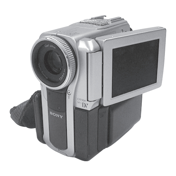
Photo : DCR-PC9E
RMT-814
SPECIFICATIONS
Fastforward/rewind time
(using cassette DVM60)
Approx. 2 min. and 30 seconds
Viewfinder
Electric viewfinder (colour)
Total dot number:
DCR-PC9/PC9E: 180 000 (800 × 225)
DCR-PC6E: 113 578 (521 × 218)
Image device
4.5 mm (1/4 type) CCD
(Charge Coupled Device)
DCR-PC9:
Approx. 680 000 pixels
(Effective: 340 000 pixels)
DCR-PC6E/PC9E:
Approx. 800 000 pixels
(Effective: 400 000 pixels)
Lens
Carl Zeiss
Combined power zoom lens
Filter diameter 30 mm. (1 3/16 in.)
10× (Optical), 120× (Digital)
Focal length
3.3 - 33 mm (5/32 - 1 5/16 in.)
When converted to a 35 mm still
camera 42 - 420 mm (1 11/16 - 16 5/
8 in.)
DIGITAL VIDEO CAMERA RECORDER
Hong Kong Model
For MECHANISM ADJUSTMENTS, refer to the
"DV MECHANICAL ADJUSTMENT MANUAL
J MECHANISM " (9-929-807-11).
NTSC model : DCR-PC9
PAL model
: DCR-PC6E/PC9E
Colour temperature
Auto, HOLD (Hold),
Indoor
(3 200K),
Outdoor (5 800K)
Minimum illumination
5 lx (lux) (F 1.7)
0 lx (lux) (in the NightShot mode)*
* Objects unable to be seen due to
the dark can be shot with infrared
lighting.
Input/Output connectors
S video input/output (DCR-PC9/
PC9E)
S video output (DCR-PC6E)
4-pin mini DIN
Luminance signal: 1 Vp-p,
75 Ω (ohms), unbalanced, sync
negative
Chrominance signal:
DCR-PC9: 0.286 Vp-p,
DCR-PC6E/PC9E: 0.3 Vp-p
75 Ω (ohms), unbalanced
Audio/Video input/output (DCR-
PC9/PC9E)
RMT-814
US Model
Canadian Model
Korea Model
DCR-PC9
AEP Model
UK Model
DCR-PC6E/PC9E
E Model
Tourist Model
DCR-PC9/PC9E
Australian Model
Chinese Model
DCR-PC9E
J MECHANISM
Audio/video output (DCR-PC6E)
AV MINI JACK, input/output auto
switch
Video signal: 1 Vp-p, 75 Ω (ohms),
unbalanced, sync negative
Audio signal: 327 mV, (at output
impedance more than 47 kΩ
(kilohms) )
Input impedance with more than
47 kΩ (kilohms)
Output impedance with less than
2.2 kΩ (kilohms)
DV input/output (DCR-PC9/PC9E)
DV output (DCR-PC6E)
4-pin connector
Headphone jack
Stereo minijack (ø 3.5 mm)
LANC
jack
Stereo mini-minijack (ø 2.5 mm)
USB jack (DCR-PC9/PC9E only)
mini-B
— Continued on next page —
Advertisement
Table of Contents

Related Manuals for Sony DCR-PC6E


Summary of Contents for Sony DCR-PC6E
- Page 1 DCR-PC9/PC9E: 180 000 (800 × 225) * Objects unable to be seen due to impedance more than 47 kΩ 2 rotary heads DCR-PC6E: 113 578 (521 × 218) the dark can be shot with infrared (kilohms) ) Helical scanning system Image device lighting.
-
Page 2: Self-Diagnosis Function
SELF-DIAGNOSIS FUNCTION SELF-DIAGNOSIS FUNCTION SELF-DIAGNOSIS DISPLAY When problems occur while the unit is operating, the self-diagnosis When problems occur while the unit is operating, the counter of the function starts working, and displays on the viewfinder or LCD viewfinder or LCD screen consists of an alphabet and 4-digit screen what to do. -
Page 3: Self-Diagnosis Code Table
SELF-DIAGNOSIS CODE TABLE Self-diagnosis Code Block Detailed Symptom/State Correction Function Code Non-standard battery is used. Use the info LITHIUM battery. Condensation. Remove the cassette, and insert it again after one hour. Video head is dirty. Clean with the optional cleaning cassette. LOAD direction. -
Page 4: Overall Block Diagram (1/3)(Dcr-Pc6E)
DCR-PC6E/PC9/PC9E SECTION 3 BLOCK DIAGRAMS 3-1. OVERALL BLOCK DIAGRAM (1/3)(DCR-PC6E) ( ) : Page No. shown in ( ) indicates the page to refer on the schematic diagram. CF-085 BOARD(1/2) CF-085 BOARD(1/2) VC-265/265A BOARD(1/3) LENS ASSY LENS ASSY (4-12) (4-12) -
Page 5: Overall Block Diagram (1/3)(Dcr-Pc9/Pc9E)
DCR-PC6E/PC9/PC9E 3-2. OVERALL BLOCK DIAGRAM (1/3)(DCR-PC9/PC9E) ( ) : Page No. shown in ( ) indicates the page to refer on the schematic diagram. VC-265/265A BOARD(1/3) (4-26) 16Mbit IC2202 SDRAM CF-085 BOARD(1/2) • LENS-EVF BLOCK A0-A11 D1-D15 (4-11) (4-20) IRIS... -
Page 6: Overall Block Diagram
DCR-PC6E/PC9/PC9E 3-3. OVERALL BLOCK DIAGRAM (2/3) ( ) : Page No. shown in ( ) indicates the page to refer on the schematic diagram. CN004 J MECHA DECK (4-55) FOR ADJUSTMENTS (4-40) RF MON VC-265/265A BOARD(2/3) IC102 REC CK REC CK... - Page 7 DCR-PC6E/PC9/PC9E 3-4. OVERALL BLOCK DIAGRAM (3/3) ( ) : Page No. shown in ( ) indicates the page to refer on the schematic diagram. CN012 CN3108 CN3107 VC-265/265A BOARD(3/3) TOUCH TP R,TP L,TP BOT,TP TOP PANEL (TP-1770) (4-33) CN2101 CN2103...
-
Page 8: Power Block Diagram
DCR-PC6E/PC9/PC9E 3-5. POWER BLOCK DIAGRAM (1/2) ( ) : Page No. shown in ( ) indicates the page to refer on the schematic diagram. BJ-002/002A BOARD VC-265/265A BOARD(1/2) BT901 (SEE PAGE 4-66) BATTERY TERMINAL CN3105 CN3108 CN012 BATT UNREG BATT UNREG... - Page 9 DCR-PC6E/PC9/PC9E 3-6. POWER BLOCK DIAGRAM (2/2) ( ) : Page No. shown in ( ) indicates the page to refer on the schematic diagram. VC-265/265A BOARD(2/2) CN013 CN603 J604 LANC DC LANC DC 21 21 LANC S601 RESET BTT LI 3V...
- Page 10 DCR-PC6E/PC9/PC9E SECTION 4 PRINTED WIRING BOARDS AND SCHEMATIC DIAGRAMS 4-1. FRAME SCHEMATIC DIAGRAM (1/2) LENS ASSY CN3702 CN3355 MF_VCC HCK1 MF-325 MF_A HCK2 MF_B LCD902 BOARD COLOR EVF CF-085 BOARD 1/2 CD BLOCK 2/2 SE BLOCK CN3353 MT_4.8V SE3450 SE3451...
- Page 11 DCR-PC6E/PC9/PC9E FRAME SCHEMATIC DIAGRAM (2/2) CN6101 CN011 REG_GND MS_VCC(D_3.1V) FP-347 SLCK SCLK MEMORY FLEXIBLE STICK MS_IN CONNECTOR D6101 VC-265/265A BOARD(2/2) TO VC-265/265A BOARD(1/2) REG_GND FH(1/2) MS_LED (MS ACCESS) MS_LED_VCC DCR-PC9/PC9E CN012 ND901 BACK LIGHT CN2104 N.C. INVERTER UNIT CN3108 LCD901 2.5INCH...
- Page 12 DCR-PC6E/PC9/PC9E 4-2. PRINTED WIRING BOARDS AND SCHEMATIC DIAGRAMS THIS NOTE IS COMMON FOR WIRING BOARDS AND SCHEMATIC DIAGRAMS (In addition to this, the necessary note is printed in each block) (For printed wiring boards) (Measuring conditions voltage and waveform) • b: Pattern from the side which enables seeing.
- Page 13 DCR-PC6E/PC9/PC9E MF-325 (MF SENSOR), NS-013 (REMOTE COMMANDER RECEIVER) PRINTED WIRING BOARDS — Ref. No. MF-325, NS-013 Boards; 20,000 Series — For printed wiring board • Refer to page 4-78 for parts location. (NS-013 board) • MF-325 board consists of multiple layers. However, only the sides (layers) A and B are shown.
- Page 14 DCR-PC6E/PC9/PC9E CF-085 (CCD IMAGER, PITCH/YAW SENSOR) PRINTED WIRING BOARD — Ref. No. CF-085 Board; 20,000 Series — For printed wiring board • Refer to page 4-78 for parts location. • This board consists of multiple layers. However, only the sides (layers) A and B are shown.
- Page 15 DCR-PC6E/PC9/PC9E For Schematic Diagram • Refer to page 4-9 for CF-085 printed wiring board. • Refer to page 4-7 for MF-325, NS-013 printed wiring boards. • Refer to page 4-73 for waveforms. CF-085 BOARD(1/2) Precautions Upon Replacing CCD imager CCD IMAGER(CD BLOCK) The CF-085 board mounted as a repair part is not equipped •...
- Page 16 DCR-PC6E/PC9/PC9E For Schematic Diagram • Refer to page 4-9 for printed wiring board. CF-085 BOARD(2/2) C3467 C3462 C3465 Note : Note : PITCH,YAW SENSOR(SE BLOCK) SE3450 C3459 C3466 C3464 R3452 R3453 The components identified by Les composants identifiés par (PITCH SENSOR) 0.047u...
-
Page 17: Flexible Board
DCR-PC6E/PC9/PC9E FP-100 (MODE SWITCH), FP-228 (DEW SENSOR), FP-102 (TAPE TOP/END SENSOR, S/T REEL) FLEXIBLE BOARDS Q902 TAPE TOP SENSOR FP-102 FLEXIBLE BOARD 1-677-085- D901 S903 (CC DOWN) (TAPE LED) S901 (REC PROOF) CN901 Q901 TAPE END SENSOR H902 T REEL... -
Page 18: Memory Stick Connector
DCR-PC6E/PC9/PC9E FP-347 FLEXIBLE (DCR-PC9/PC9E) MEMORY STICK CONNECTOR D6101 TLSU1008(T05,SOY) MS_LED_VCC (MS ACCESS) MS_LED CN6101 REG_GND VC-265/265A BOARD(5/18) CN011 (SEE PAGE 4-28) MS_IN SCLK MS_VCC(D_3.1V) REG_GND SLCK LND6101 SIGNAL PATH LND6102 VIDEO SIGNAL CHROMA Y/CHROMA MEMORY STICK CONNECTOR 4-57 4-58 FP-347 FLEXIBLE... -
Page 19: Control Switch Block
DCR-PC6E/PC9/PC9E For Schematic Diagram • Refer to page 4-59 for control switch block (FK-1770) printed wiring board. CONTROL SWITCH BLOCK (FK-1770) LND607 S602 RV601 ZOOM PHOTO FB605 (PHOTO_FREEZE) J603 FB604 S605 S603 R607 FOCUS PHOTO 1500 (PLUG IN POWER) 1608... - Page 20 • Refer to page 4-78 for parts location (BJ-002/002A board). There are a few cases that the part printed on PO-007 BJ-002A Board : DCR-PC6E • BJ-002/002A board consists of multiple layers. How- (PANEL OPEN) this diagram isn’t mounted in this model.
- Page 21 DCR-PC6E/PC9/PC9E For Schematic Diagram • Refer to page 4-63 for BJ-002/002A printed wiring board. • Refer to page 4-63 for PO-007 printed wiring board. • Refer to page 4-63 for PR-037 printed wiring board. BJ-002/002A BOARD NO MARK:REC/PB MODE JACK,BATTERY...
- Page 22 DCR-PC6E/PC9/PC9E For Schematic Diagram • Refer to page 4-67 for printed wiring board. • Refer to page 4-73 for waveforms. PD-148/148A BOARD(1/2) LCD DRIVE(RGB,TG BLOCK) L2103 C2115 Q2104 10uH 3.3u -REF.NO.:20000 SERIES- C2114 NDS356AP 0.01u 2520 SWITCH XX MARK:NO MOUNT 13.6...
- Page 23 DCR-PC6E/PC9/PC9E For Schematic Diagram • Refer to page 4-67 for printed wiring board. PD-148/148A BOARD(2/2) BACK LIGHT(BL BLOCK) -REF.NO.:20000 SERIES- XX MARK:NO MOUNT NO MARK:REC/PB MODE L2181 DUMY_LND 4.7uH LND2181 3225 UNREG PANEL_UNREG BL_HI Q2182 2SA1832F-Y/GR(TPL3) LND2182 SWITCH PANEL_4.6V L2182...
- Page 24 DCR-PC6E/PC9/PC9E 4-3. WAVEFORMS PD-148/148A CF-085 BOARD BOARD REC/PB CAMERA REC IC2101 rh IC2103 rk IC3201 1 2.8Vp-p 6.5Vp-p 560mVp-p IC2101 rj IC3201 2 18.0Vp-p 480mVp-p IC2101 rk IC3201 3 6.5Vp-p 600mVp-p Waveforms and parts location of the VC-265/265A board are not shown.
Need help?
Do you have a question about the DCR-PC6E and is the answer not in the manual?
Questions and answers