Table of Contents
Advertisement
www.iconfitness.com
Model No. SFTL19511.1
Serial No.
Write the serial number in the
space above for reference.
Serial Number
Decal
ACTIVATE YOUR
WARRANTY
To register your product and
activate your warranty today, go to
www.iconservice.com/registration.
CUSTOMER CARE
For service at any time, go to
www.iconservice.com.
Or call 1-800-999-3756
Mon.––Fri. 6 a.m.––6 p.m. MT
Sat. 8 a.m.––4 p.m. MT
Please do not contact the store.
CAUTION
Read all precautions and instruc-
tions in this manual before using
this equipment. Save this manual
for future reference.
USER’'S MANUAL
Advertisement
Table of Contents
Troubleshooting

Subscribe to Our Youtube Channel
Related Manuals for Freemotion 790 Interactive


Summary of Contents for Freemotion 790 Interactive
- Page 1 www.iconfitness.com Model No. SFTL19511.1 USER’’S MANUAL Serial No. Write the serial number in the space above for reference. Serial Number Decal ACTIVATE YOUR WARRANTY To register your product and activate your warranty today, go to www.iconservice.com/registration. CUSTOMER CARE For service at any time, go to www.iconservice.com.
-
Page 2: Table Of Contents
Apply the decal in the location shown. Note: The decals may not be shown at actual size. FREEMOTION is a registered trademark of ICON IP, Inc. -
Page 3: Important Precautions
17. informed of all warnings and precautions. To purchase a surge suppressor, see your local FREEMOTION dealer, call the telephone 3. Use the treadmill only as described. number on the front cover of this manual, or see your local electronics store. - Page 4 20. Never leave the treadmill unattended while 28. Do not store the television in temperatures it is running. Always remove the key, unplug below -40° F (-40° C) or above 140° F (60° C). the power cord, and press the power switch Do not operate the television in temperatures into the off position when the treadmill is not below 23°...
- Page 5 33. Upon completion of any service or repairs to 37. Use a jumper wire not smaller than No. 6 the treadmill or the television, ask the ser- AWG (13.3 mm ) copper, or the equivalent, vice technician to perform safety checks to when a separate antenna-grounding elec- confirm that the unit is in proper operating trode is used.
-
Page 6: Before You Begin
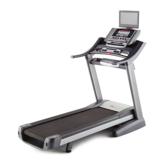
BEFORE YOU BEGIN Thank you for selecting the revolutionary reading this manual, please see the front cover of this FREEMOTION 790 INTERACTIVE treadmill. The 790 manual. To help us assist you, please note the product ® INTERACTIVE treadmill offers an impressive selec- model number and serial number before contacting us. -
Page 7: Part Identification Chart
PART IDENTIFICATION CHART Use the drawings below to identify small parts used for assembly. The number in parentheses below each draw- ing is the key number of the part, from the PART LIST near the end of this manual. The number following the key number is the quantity used for assembly. -
Page 8: Assembly
ASSEMBLY •• Assembly requires two persons. •• Assembly requires the following tools: •• Place all parts in a cleared area and remove the •• the included hex key packing materials. Do not dispose of the packing materials until you nish all assembly steps. ••... - Page 9 3. Identify the Left Upright (89), which is marked ““Left.”” Have a second person hold the Left Upright near the Base (97). See the inset drawing. Tie the wire tie in the Left Upright (89) securely around the end of the Upright Wire (84).
- Page 10 5. Identify the Left and Right Base Covers (92, 93). Slide the Left Base Cover onto the Left Upright (89). Slide the Right Base Cover onto the Right Upright (90). Do not press the Base Covers into place yet. 6. Attach a Tray Bracket (105) to the side of the Left Upright (89) with two #8 x 3/4"...
- Page 11 7. With the help of a second person, hold the con- sole assembly near the Left Upright (89). Connect the Upright Wire (84) to the console Console wire. See the inset drawing. The connectors Assembly should slide together easily and snap into place.
- Page 12 9. Insert the wires into the Left and Right Uprights (89, 90) as you set the console assembly on the Uprights. Be careful not to pinch the wires. Console Assembly Attach the console assembly with four 5/16" x 1 1/2" Screws (5) and four 5/16" Star Washers (10).
- Page 13 11. Attach the Fan Tray (30) to the Tray Brackets (105) with four #8 x 3/4" Screws (1) (only one side is shown). Start all four Screws, and then tighten them. Then, insert any excess wire from the Fan Tray into the Right Upright (not shown). 12.
- Page 14 13. Raise the Frame (56) to the position shown. Have a second person hold the Frame until this step is completed. Orient the Storage Latch (53) so that the large barrel and the latch knob are oriented as shown. Attach the lower end of the Storage Latch (53) to the Base (97) with a 3/8"...
- Page 15 16. Hold the TV assembly near the console assem- bly, and connect the wires. TV Assembly Attach the TV assembly to the back of the con- sole assembly with four 1/4" x 1/2" Screws (119). Be careful not to pinch any wires. Start all Console four Screws, and then tighten them.
-
Page 16: The Chest Heart Rate Monitor
THE CHEST HEART RATE MONITOR HOW TO PUT ON THE HEART RATE MONITOR •• Do not expose the heart rate monitor to direct sunlight for extended periods of time; do not expose The heart rate it to temperatures above 122° F (50° C) or below 14° monitor consists of F (-10°... -
Page 17: Operation And Adjustment
OPERATION AND ADJUSTMENT HOW TO CONNECT THE POWER CORD more amps. To avoid overloading the circuit, do not plug other electrical devices, except for low- Use a Surge Suppressor power devices such as cell phone chargers, into the surge suppressor or into an outlet on the same Your treadmill, like other electronic equipment, can be circuit. - Page 18 Before operating the 15" digital TV, you must connect an antenna or a 75 ohm CATV cable to the 75 ohm terminal, an AV cable to the audio/video input jack, or an HDMI cable to the HDMI input jack. Note: Use a CATV cable to connect to an external source such as a cable box, satellite TV box, VCR, or analog cable.
- Page 19 HOW TO CONNECT A VCR, DVD PLAYER, OR HOW TO CONNECT A DVD OR BLU-RAY PLAYER OTHER DEVICE USING AN AV CABLE OR OTHER DEVICE USING AN HDMI CABLE 1. Connect the three-pronged end of an RCA AV 1. Connect one end of an HDMI Cable to your DVD or Cable to your VCR, DVD player, or other device.
- Page 20 CONSOLE DIAGRAM FEATURES OF THE CONSOLE As you exercise, the console will display instant exer- cise feedback. You can also measure your heart rate The treadmill console offers an impressive array of using the handgrip heart rate monitor or the chest heart features designed to make your workouts more effec- rate monitor.
- Page 21 HOW TO TURN ON THE POWER HOW TO USE THE TOUCH SCREEN IMPORTANT: If the treadmill has been exposed to The console features a tablet with a full-color touch cold temperatures, allow it to warm to room tem- screen. The following information will help you become perature before you turn on the power.
- Page 22 HOW TO SET UP THE CONSOLE the Place of Purchase drop-down menu for a list of options; then, touch the location where you pur- Before using the treadmill for the first time, set up the chased your product. Touch the words MEDICAL console.
- Page 23 HOW TO USE THE MANUAL MODE Each time you press one of the buttons, the incline will gradually change until it reaches the selected 1. Insert the key into the console. incline setting. See HOW TO TURN ON THE POWER on page Note: The first time you adjust the incline, you must 21.
- Page 24 If desired, adjust the con- 7. Turn on the fan if desired. sole volume by pressing the volume increase and The fan features several speed settings. Press one decrease buttons on the of the numbered Fan buttons to select a fan speed. console.
- Page 25 HOW TO USE AN ONBOARD WORKOUT screen. After you view the workout summary, touch the Finish button to return to the main menu. You 1. Insert the key into the console. may also be able to either save or publish your results using one of the options on the screen.
- Page 26 HOW TO USE A SET-A-GOAL WORKOUT The workout will function in the same way as the manual mode (see pages 23 and 24). 1. Insert the key into the console. The workout will continue until you reach the goal See HOW TO TURN ON THE POWER on page that you set.
- Page 27 HOW TO USE AN IFIT LIVE WORKOUT Before some workouts will download, you must add them to your schedule on iFit.com. Note: To use an iFit Live workout, you must have access to a wireless network (see HOW TO USE THE For more information about the iFit Live work- WIRELESS NETWORK MODE on page 30).
- Page 28 HOW TO USE THE EQUIPMENT SETTINGS MODE reset position, and insert the key into the console. However, when you remove the key, the screen will The console features an equipment settings mode show a demo presentation. that allows you to select a language and the unit of measurement, to turn on and turn off the display demo To turn on or turn off the display demo mode, first mode, and to enable or disable the key.
- Page 29 HOW TO USE THE MAINTENANCE MODE computer and plug it into the USB port on the side of the console. The update should begin automati- The console features a maintenance mode that allows cally. Do not plug any USB devices into the USB you to update the console firmware, calibrate the port on the side of the 15"...
- Page 30 HOW TO USE THE WIRELESS NETWORK MODE An information box will ask if you want to connect to the wireless network. Touch the Connect button The console features a wireless network mode that to connect to the network or touch the Cancel but- allows you to set up a wireless network connection.
- Page 31 HOW TO USE THE SOUND SYSTEM HOW TO USE THE INTERNET BROWSER To play music or audio books through the console Note: To use the browser, you must have access to a sound system while you exercise, plug a 3.5 mm male wireless network including an 802.11b/n router with to 3.5 mm male audio cable (not included) into the jack SSID broadcast enabled (hidden networks are not...
- Page 32 HOW TO OPERATE THE 15" DIGITAL TV 5. Mute the TV if desired. The 15" digital TV can be controlled Press the Mute button to silence the TV’’s audio using the control buttons found on your output. Press the button again or adjust the volume exercise equipment’’s console or with to turn the TV off of mute.
- Page 33 HOW TO USE THE REMOTE CONTROL Press the Display button to view information about the current program and the broadcast or cable signal. The first time you use the remote control, insert batteries (see HOW TO Press the CC button repeatedly to turn on or turn off REPLACE THE BATTERIES IN THE closed captioning.
- Page 34 HOW TO ADJUST THE TELEVISION SETTINGS 4. Adjust the channel settings. The 15" digital TV has a menu that allows you to adjust The Channel menu allows you to save channels and personalize television settings. in the TV memory and select settings for chan- nels.
- Page 35 5. Adjust the parental control settings. Select Menu Language to change the language used in the menus. The Parental menu allows you to block or allow various settings on the 15" digital TV. Select Clock to adjust the TV clock’’s time zone, auto setting, time setting, day of the week setting, First, enter the Lock Parental Code password, and daylight saving time setting.
-
Page 36: How To Fold And Move The Treadmill
HOW TO FOLD AND MOVE THE TREADMILL HOW TO FOLD THE TREADMILL HOW TO MOVE THE TREADMILL To avoid damaging the treadmill, adjust the incline Before moving the treadmill, fold it as described at the to zero before you fold the treadmill. Then, remove left. -
Page 37: Troubleshooting
TROUBLESHOOTING Most treadmill problems can be solved by follow- c. Remove the key from the console, and then ing the simple steps below. Find the symptom that reinsert it. applies, and follow the steps listed. If further assis- tance is needed, see the front cover of this manual. d. - Page 38 Lower the treadmill (see HOW TO LOWER THE SYMPTOM: The walking belt slows when walked on TREADMILL FOR USE on page 36). Remove the three #8 x 3/4" Screws (1). Carefully pivot the a. Use only a surge suppressor that meets all of the Motor Hood (71) off.
- Page 39 SYMPTOM: The walking belt is off-center or slips SYMPTOM: The iFit Live mode does not function when walked on correctly a. If the walking belt is off-center, first remove the a. If the iFit Live mode is not functioning correctly, key and UNPLUG THE POWER CORD.
- Page 40 SYMPTOM: The volume cannot be turned up •• Ignition (black spots or horizontal streaks that appear or a picture that flutters or drifts)——Usually a. If there is no sound coming from the television, this is caused by interference from automobile igni- make sure that the television audio is not muted.
-
Page 41: Exercise Guidelines
EXERCISE GUIDELINES Burning Fat——To burn fat effectively, you must exer- WARNING: cise at a low intensity level for a sustained period of Before beginning this time. During the first few minutes of exercise, your or any exercise program, consult your physi- body uses carbohydrate calories for energy. -
Page 42: Part List
PART LIST Model No. SFTL19511.1 R0813A Key No. Qty. Description Key No. Qty. Description #8 x 3/4" Screw Reed Switch Clamp Pulse Ground Wire Reed Switch 3/8" x 2" Bolt Storage Latch 5/16" x 2" Screw Drive Motor 5/16" x 1 1/2" Screw Motor Belt 3/8"... - Page 43 Key No. Qty. Description Key No. Qty. Description Wheel Cushion Tube Console Base 3/8" Flat Washer Console Upright Coaxial Cable TV Bracket M4.2 x 12mm Screw Tray Bracket TV Bracket Cover Handrail Spacer #8 x 3/8" Screw Console Frame 1/4" x 1/2" Screw Platform Cushion Bracket 5/16"...
-
Page 44: Exploded Drawing
EXPLODED DRAWING A Model No. SFTL19511.1 R0813A... - Page 45 EXPLODED DRAWING B Model No. SFTL19511.1 R0813A...
- Page 46 EXPLODED DRAWING C Model No. SFTL19511.1 R0813A...
- Page 47 EXPLODED DRAWING D Model No. SFTL19511.1 R0813A 118 117...
-
Page 48: Ordering Replacement Parts
ORDERING REPLACEMENT PARTS To order replacement parts, please see the front cover of this manual. To help us assist you, be prepared to provide the following information when contacting us: •• the model number and serial number of the product (see the front cover of this manual) ••...
Need help?
Do you have a question about the 790 Interactive and is the answer not in the manual?
Questions and answers
how to disassemble