Table of Contents
Advertisement
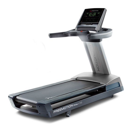
Model No. FMTL39813.2
Serial No.
Write the serial number in the space
above for reference.
Serial Number Decal
QUESTIONS?
If you have questions, or if parts
are damaged or missing,
please see HOW TO CONTACT
CUSTOMER CARE on the back
cover of this manual.
CAUTION
Read all precautions and instruc-
tions in this manual before using
this equipment. Save this manual
for future reference.
USER'S MANUAL
www.freemotionfitness.com
Advertisement
Table of Contents


Need help?
Do you have a question about the FMTL39813.2 and is the answer not in the manual?
Questions and answers