Matrix T3x Series Owner's Manual
Hide thumbs
Also See for T3x Series:
- Error code list (13 pages) ,
- Manual (124 pages) ,
- Console manual (84 pages)
Table of Contents
Advertisement
Advertisement
Table of Contents

Related Manuals for Matrix T3x Series


Summary of Contents for Matrix T3x Series
- Page 1 T 3 x S E R I E S T R E A D M I L L O W N E R ’ S M A N U A L...
-
Page 2: Table Of Contents
ABLE OF ONTENTS IMPORTANT SAFETY INSTRUCTIONS Proper Usage Check for Damaged Parts Important Safety Instructions Electrical Requirements Grounding Instructions SETTING UP THE TREADMILL Unpacking Treadmill Contents OVERLAY DESCRIPTION AND CUSTOM SETTING Console Description Engineering Mode Manager Screen Description/Details Using CSAFE MAINTENANCE Recommended Cleaning Tips Deck and Belt Replacment... -
Page 3: Important Safety Instructions
1.0 I MPORTANT AFETY NSTRUCTIONS It is the sole responsibility of the purchaser of Matrix Fitness Systems products to instruct 1.1 IMPORTANT SAFETY INSTRUCTIONS all individuals, whether they are the end user or supervising personnel on proper usage of the equipment. -
Page 4: Electrical Requirements
For your safety and treadmill performance, the ground on this circuit must be non-looped. The Matrix MX-T3x 120 treadmill is for use on a nominal 120-volt circuit and has a non- Please refer to NEC article 210-21 and 210-23. Your Treadmill is provided with a power looped grounding plug. -
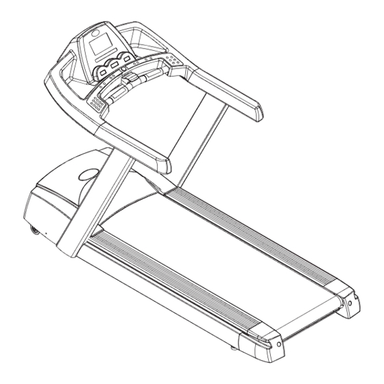
Page 5: Setting Up The Treadmill
READMILL 2.1 UNPACKING THE TREADMILL 2.2 CONTENTS The MATRIX treadmill is inspected before it is packaged. It is shipped in four pieces: the 1. Frame base, the upright console supports, the handlebar and the console. Carefully unpack the 2. Console Supports unit and dispose of the box material. -
Page 6: Overlay Description And Custom Setting
3.0 O VERLAY ESCRIPTION AND USTOM ETTINGS 3.1 CONSOLE DESCRIPTION 3.2 ENGINEERING MODE Engineering screens allow the viewing and editing of variables that would be necessary for a club operator/manager to customize. Unless otherwise noted engineering screens consist of the initial screen, the editing or action screen and the saving screen. The initial screen displays the variable type and in most cases the current value. -
Page 7: Using Csafe
Displays the product's software version. Version is not editable, for display only. 3.4 USING CSAFE LANGUAGE Matrix is the leader in entertainment availability. On the back of the console is an RJ45 Language in which information is displayed. receptacle. They are marked CSAFE IN. -
Page 8: Maintenance
2 inches on both sides removing any dust or debris. The deck can be flipped and reinstalled or replaced by an authorized service technician. Please contact Matrix Fitness Systems for more information. 4.3 ADJUSTING THE BELT After placing the treadmill in the position it will be used, the belt must be checked for proper tension and centering. -
Page 9: Operating The Programs
ROGRAMS 5.1 MANUAL OPERATION 5.3 HEAT RATE CONTROL Follow these easy Steps to enter into the Heart Rate Program. MATRIX design makes using the programs as easy as one touch of a button. TARGET HR TARGET HR QUICK START Press the “QUICK START” key and the LED will show “3”, “2”, “1”, “GO!”. The treadmill 1) Choose the “TARGET HR”... -
Page 10: Equipment Specifications
6.0 E QUIPMENT PECIFICATIONS 6.1 SPECIFICATIONS HEART RATE Foot Print inches = 85” x 34” x 55” Telemetry cm = 216 x 87 x 140 Contact Heart Rate Weight 350 lbs 159 kg ENTERTAINMENT READY Max User Weight 400 lbs = 181 kg Belt Type Habisat CSAFE Port... -
Page 11: Assembly
7.0 A SSEMBLY 7.1 ASSEMBLY & HARDWARE REF # DESCRIPTION • ATTENTION Screw Driver After installation is completed, the treadmill will need to be calibrated by using the AUTO-CHECK function. If this is not done, the treadmill's speed and incline values may be incorrect and damage the Wrench (M8) treadmill. - Page 12 7.0 A SSEMBLY 7.1 ASSEMBLY & HARDWARE STEP 3 STEP 4 Put the handle bar into the handle bar frame. Use the handle bar cap (N06, Place the motor cover onto the treadmill front end and secure with the screws (Z53) provided. Plug the power N07) to secure the handle bar.
Need help?
Do you have a question about the T3x Series and is the answer not in the manual?
Questions and answers