Do you have a question about the COMBI ESP 24 and is the answer not in the manual?
Questions and answers
San
March 12, 2025
Hello why **** I getting heat in radiators upstairs but only slightly aired downstairs esp 35 I have bled radiators I have topped up the pressure
1 comments:
Mr. Anderson
March 12, 2025
The issue may be due to trapped air, an unbalanced system, or a circulation problem. After bleeding and topping up the pressure, air could still be trapped in the system, preventing proper circulation to the downstairs radiators. Additionally, if the system is unbalanced, more hot water may be flowing to the upstairs radiators. Adjusting the lockshield valves on the upstairs radiators to restrict flow and allow more heat to reach the downstairs radiators may help. If the problem persists, the pump may not be circulating water effectively, or there could be a blockage in the system. Checking the pump operation and ensuring no blockages in the pipework would be the next step.
This answer is automatically generated
Thomas Crawford
August 3, 2025
The switch off/heaters/water and heaters is stuck at off.
Sandra
March 12, 2025
Logic 35 combi
1 comments:
Mr. Anderson
March 12, 2025
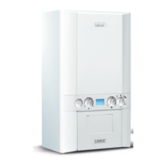
The IDEAL LOGIC COMBI ESP 24 is a condensing combination (combi) boiler that operates using gas as its fuel source. It has a SAP seasonal efficiency rating of 89.0%, meaning it is designed to provide efficient heating while reducing fuel consumption and carbon dioxide emissions. The boiler features a room-sealed, fan-assisted flue system and has a maximum power output of 24.2 kW. Its condensing technology improves energy efficiency by capturing and reusing heat that would otherwise be lost in waste gases.


Need help?
Do you have a question about the COMBI ESP 24 and is the answer not in the manual?
Questions and answers
Hello why **** I getting heat in radiators upstairs but only slightly aired downstairs esp 35 I have bled radiators I have topped up the pressure
The issue may be due to trapped air, an unbalanced system, or a circulation problem. After bleeding and topping up the pressure, air could still be trapped in the system, preventing proper circulation to the downstairs radiators. Additionally, if the system is unbalanced, more hot water may be flowing to the upstairs radiators. Adjusting the lockshield valves on the upstairs radiators to restrict flow and allow more heat to reach the downstairs radiators may help. If the problem persists, the pump may not be circulating water effectively, or there could be a blockage in the system. Checking the pump operation and ensuring no blockages in the pipework would be the next step.
This answer is automatically generated
The switch off/heaters/water and heaters is stuck at off.
Logic 35 combi
The IDEAL LOGIC COMBI ESP 24 is a condensing combination (combi) boiler that operates using gas as its fuel source. It has a SAP seasonal efficiency rating of 89.0%, meaning it is designed to provide efficient heating while reducing fuel consumption and carbon dioxide emissions. The boiler features a room-sealed, fan-assisted flue system and has a maximum power output of 24.2 kW. Its condensing technology improves energy efficiency by capturing and reusing heat that would otherwise be lost in waste gases.
This answer is automatically generated