Table of Contents
Advertisement
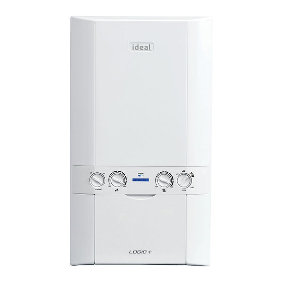
iNSTALLATioN
AND SERViciNg
Logic+ SYSTEM
15 18 24 30
For Users Guide see reverse of book
When replacing any part on this appliance, use only spare parts that you can be
assured conform to the safety and performance specification that we require.
Do not use reconditioned or copy parts that have not been clearly authorised by Ideal.
For the very latest copy of literature for specification and maintenance practices visit our
website www.idealboilers.com where you can download the relevant information in PDF format.
May 2015
UIN 212122 A01
Advertisement
Chapters
Table of Contents


Need help?
Do you have a question about the Logic+ SYSTEM 15 and is the answer not in the manual?
Questions and answers
Hi our boiler is flashing F 1 and not producing hot water, please can you advise on what we should do.
The F1 error code on the IDEAL SYSTEM 15 boiler indicates "Low Water Pressure."
To resolve it:
1. Check the system pressure gauge; if it's below 0.3 bar, the boiler will not operate.
2. Repressurize the system to the correct level (typically around 1.0–1.5 bar).
3. If the error persists, check for leaks or pressure drops in the system.
If the issue remains unresolved, further inspection by a qualified engineer may be needed.
This answer is automatically generated