
Subscribe to Our Youtube Channel
Related Manuals for Omron S8BA-24D24D120LF


Summary of Contents for Omron S8BA-24D24D120LF
- Page 1 Uninterruptible Power Supply (UPS) S8BA-24D24D□□□LF User's Manual S8BA-24D24D120LF S8BA-24D24D240LF S8BA-24D24D360LF/S8BA-24D24D480LF...
-
Page 3: Introduction
Introduction Introduction Thank you for purchasing OMRON's Uninterruptible Power Supply (UPS). This manual contains information that is necessary to use the “Uninterruptible Power Supply (UPS)”. Read this manual carefully and make sure that you understand the functionality and performance of the product before using it in your system. -
Page 4: Procedure From Installation To Operation
Procedure from installation to operation Procedure from installation to operation The procedure from installation to operation is shown below. Read “Safety Precautions” Start Page 8 Remove the product from the package and check the contents 2. Preparation Installation/connection Perform installation and connection 3. -
Page 5: Table Of Contents
Table of contents Table of contents Introduction ....................1 Procedure from installation to operation ............2 Table of contents ..................3 Read and understand this manual ............... 5 Safety precautions ..................8 Regulations and standards ................ 17 Overview of the product ..............19 Features of this product ................. - Page 6 Table of contents UPS operation mode settings ................ 61 4-4-1 Settable items and explanations ..................61 4-4-2 Settings ..........................64 Maintenance and inspection .............. 71 Checking the battery ..................71 5-1-1 Battery life expectancy ...................... 71 5-1-2 Self-diagnosis test ......................71 5-1-3 Estimated backup time ......................
-
Page 7: Read And Understand This Manual
・ “OMRON products”: FA system devices, general-purpose controllers, sensing devices, and electromechanical components of “OMRON” ・ “Catalogs and other documents”: Catalogs such as the OMRON Best Controllers and the Electromechanical Components General Catalog, specifications, instruction manuals, and other catalogs and manuals related to “OMRON products”, including those provided in digital form ・... - Page 8 “OMRON” shall not be responsible for the “suitability of use” of any kind. ・ Be sure to confirm on your own in advance that the “OMRON product” is provided with electrical power and installed properly for the intended use in your entire system.
- Page 9 ・ Warranty period: For a period of 1 year from the date of purchase (Unless otherwise described in “catalog or other documents”) ・ Warranty: Any of the following shall be performed on a faulty “OMRON product” at the discretion of “OMRON”.
-
Page 10: Safety Precautions
Safety precautions Safety precautions Important information for safe operation is described. Be sure to read it before installation and start of use. The safety symbols and their meaning used in this manual are as follows: If you fail to use the product properly, it may result in injuries, mild or moderate, and may Warning lead to death. - Page 11 Safety precautions Warning (for use of this product) Provide safety measures outside the UPS to ensure safety in the entire system even if the UPS is damaged or an abnormality occurs due to an external factor. Not doing so may result in serious accidents due to incorrect operation.
- Page 12 Safety precautions Caution (for installation and connection) Do not install the unit in other than specified orientations. ▪ Dropping or toppling the unit may cause injury. ▪ If you install the unit in an orientation other than specified, the internal temperature may rise, eventually damaging the UPS or deteriorating the battery.
- Page 13 Safety precautions Caution (for installation and connection) Include a breaker between the “input power supply” of this unit and the DC power supply device. And install the breaker where it is easy to operate. When this product is used in compliance with CE marking, please use under 2m communication cable.
- Page 14 Safety precautions Caution (for use) Do not use the unit in a closed place and do not cover the unit. ▪ Doing so may cause abnormal heating or a fire. If you notice something unusual such as abnormal sound or smell, discoloration, deformation, and heating, turn OFF the unit's “Power”...
- Page 15 Safety precautions Caution (for maintenance) Do not disassemble, repair, or modify the unit. ▪ Doing so may cause an electric shock or a fire. If fluid leaks from the interior, do not touch the fluid. ▪ Doing so may cause blindness or burns. ▪...
- Page 16 Safety precautions Caution (for battery replacement) Do not drop the battery and do not expose it to strong impact. ▪ Doing so may cause a leakage, abnormal heating, smoke, rupture or fire on the battery. And, if the battery's protection mechanism is broken, the battery may be charged at an abnormal current or voltage, an abnormal chemical reaction may occur inside the battery, and it may result eventually in an abnormal heating, smoke, rupture or fire.
- Page 17 Safety precautions Notes ■ Before using Charge the battery soon after purchasing the unit. ▪ If you do not use the unit for a long time after the purchase, the battery may deteriorate and the battery may become unusable. ▪ Connect this unit to the input power supply and turn ON the “Power” switch to charge the battery.
- Page 18 Safety precautions ■ Using Before stopping the input power supply to the unit, turn OFF the “Power” switch of the unit. ▪ The unit enters Battery Mode when input power supply is stopped. ▪ If the frequency of backup operation becomes high, the battery life may be significantly reduced.
-
Page 19: Regulations And Standards
Whether the products conform to the standards in the system used by the customer, however, must be checked by the customer. EMC-related performance of the OMRON devices that comply with EC Directives will vary depending on the configuration, wiring, and other conditions of the equipment or control panel on which the OMRON devices are installed. - Page 20 Regulations and standards ●Conformance to UL ▪ This product must be installed within a control panel with an internal heater or other unit to protect against the formation of condensation (Standard mounting only). ▪ Gaps in the door to the control panel must be completely filled or covered with gaskets or other material.
-
Page 21: Overview Of The Product
1-1 Features of this product 1 Overview of the product 1 Overview of the product Features of this product ▪ The Uninterruptible Power Supply (UPS) protects such devices as PLC and IPC* from power failures, voltage variations, and instantaneous voltage drops. ▪... -
Page 22: Specifications
1 Overview of the product 1-2 Specifications Specifications Description Capacity 120W 240W 360W 480W ※ Rated input voltage DC24V When standard DC24V±10% sensitivity is set) When low voltage Input voltage range DC24V±12.5% sensitivity is set When low voltage DC24V±5% sensitivity is set input Input maximum for rated input voltage... - Page 23 1-2 Specifications 1 Overview of the product *2 Conditions: With rated loads connected, at a rated input voltage, and with the battery fully charged. *3 Conditions: With rated loads connected, at a rated input voltage, and at the maximum battery charging current.
-
Page 24: Preparation
2 Preparation 2-1 Unpacking the product 2 Preparation Unpacking the product Open the package box and take out the UPS and accessories. Caution for installation and connection Carry the unit considering its weight and balance, and place it on a stable and robust base. - Page 25 2-2 Checking the contents 2 Preparation ■ Related products Description Model number Replacement battery pack S8BA-B120L* Connection cable (RS232C) S8BW-C01 Connection cable (CONTACT) S8BW-C02 * Battery pack (S8BA-B120L) information: ▪Rated voltage: DC14.4V ▪Rated capacity: 1600mAh ▪Weight: 0.3kg Connection cable Replacement Connection cable (CONTACT) battery pack...
-
Page 26: Name Of Each Part
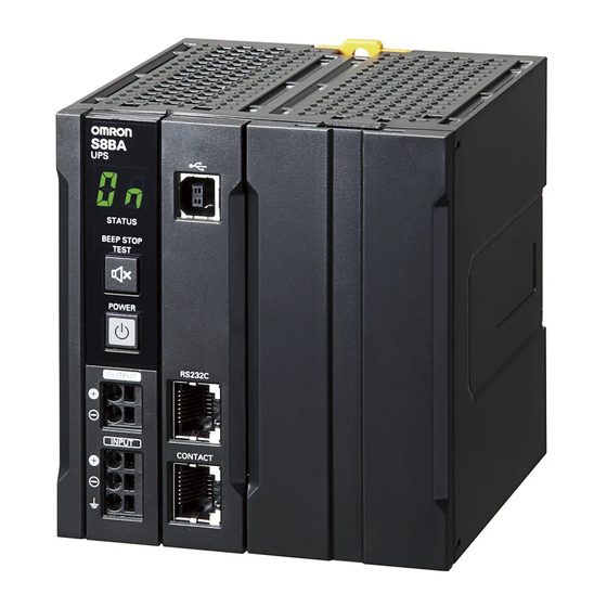
■ Meanings of the symbols Indicates that the power is turned ON. Indicates that the power is turned OFF. Indicates that the beeper is stopped. Indicates the noise-resistance improved grounding. ■ Front view ● S8BA-24D24D120LF ⑤ ① ⑥ ② ⑦... - Page 27 2-3 Name of each part 2 Preparation ● S8BA-24D24D240LF ⑤ ① ⑥ ② ③ ⑦ ④ ①Operation panel ⑤USB port ②DC output terminal block ⑥RS232C port ③DC input terminal block ⑦CONTACTport ④GR terminal ( ) ● S8BA-24D24D360LF/S8BA-24D24D480LF ② ⑤ ① ⑥...
- Page 28 2 Preparation 2-3 Name of each part ■ Enlarged view of the operation panel ⑧ ⑨ ⑩ ⑧“Status indicator” digital indicator (Green) ⑨“Beep Stop/Test” switch (Black) ⑩“Power” switch (Gray) S8BA-24D24D□□□LF...
-
Page 29: Rear View
2-3 Name of each part 2 Preparation ■ Rear view ● S8BA-24D24D120LF ⑪ ⑫ ⑪ ⑪DIN rail mounting hook ⑫DIN rail mounting groove ● S8BA-24D24D240LF ⑪ ⑫ ⑪ ⑪ ⑪DIN rail mounting hook ⑫DIN rail mounting groove S8BA-24D24D□□□LF... - Page 30 2 Preparation 2-3 Name of each part ● S8BA-24D24D360LF/S8BA-24D24D480LF ⑪ ⑪ ⑫ ⑪ ⑪ ⑪ ⑪DIN rail mounting hook ⑫DIN rail mounting groove S8BA-24D24D□□□LF...
-
Page 31: Diagram Of The Input/Output Circuit Block
2-4 Diagram of the Input/output circuit block 2 Preparation Diagram of the Input/output circuit block 。 。 DC24V DC24V Imput Imput Normal operation:ON Backup operation:OFF DC/DC Converter Normal operation:ON Backup operation:OFF Normal operation:ON Backup operation:OFF Charge/ Discharge Normal operation Battery Backup operation *In normal operation, 24 VDC is output as-is for charging the battery and from the input power supply. -
Page 32: Installation And Connection
3 Installation and connection 3-1 Installation 3 Installation and connection Installation This section describes how to install the UPS. For cautions when installing the UPS, refer to “Caution (for installation and connection)” shown in the “Safety precautions” of the beginning of this manual. The UPS permits the following installing methods. - Page 33 3-1 Installation 3 Installation and connection ● Stationary mounting To mount UPS on floor with its back away from you,mount it so that its back is in contact with wall. (Because PCB is partially exposed in its back side, and UPS may be affected by static electricity for that reason.) ●...
- Page 34 3 Installation and connection 3-1 Installation ■ Incorrect positions ● Mounting to the DIN rail Mount UPS upside down DIN rail is placed vertically S8BA-24D24D□□□LF...
- Page 35 3-1 Installation 3 Installation and connection ● Stationary installation Do not stack. Do not mount on floorwith front down. To mount UPS on floor with its top away from you, ensure that its top is not in contact with wall. S8BA-24D24D□□□LF...
-
Page 36: Din Rail Installation
3 Installation and connection 3-1 Installation 3-1-1 DIN rail installation ■ How to mount to the DIN rail Open the “DIN rail mounting hooks” in the back of the UPS. DIN rail mounting hooks DIN rail mounting hooks Hook the “DIN rail mounting groove” in the back of the UPS onto the DIN rail. Put a hook on the groove on one end (①), and put the other hook on the groove on the other end (②). - Page 37 3-1 Installation 3 Installation and connection Close the “DIN rail mounting hooks” in the back of the UPS. DIN rail mounting hooks DIN rail DIN rail mounting hooks ● Mounting on the floor DIN rail S8BA-24D24D□□□LF...
-
Page 38: Wall Or Floor Mounting Procedure
3 Installation and connection 3-1 Installation 3-1-2 Wall or floor mounting procedure Open the “DIN rail mounting hooks” in the back of the UPS. DIN rail mounting hooks DIN rail mounting hooks Use the screw holes of the “DIN rail mounting hooks” to fix the UPS to the floor or wall with screws. - Page 39 3-1 Installation 3 Installation and connection ● Mounting on the floor Screw Screw S8BA-24D24D□□□LF...
- Page 40 3 Installation and connection 3-1 Installation ● 120W Fix with screws ● 240W Fix with screws S8BA-24D24D□□□LF...
- Page 41 3-1 Installation 3 Installation and connection ● 480W Fix with screws S8BA-24D24D□□□LF...
-
Page 42: Connection
3 Installation and connection 3-2 Connection Connection This section describes how to connect the UPS. For cautions when connecting the UPS, refer to “Caution (for installation and connection)” shown in the “Safety precautions” of the beginning of this manual. 3-2-1 Connecting a cable to the input terminal block and the output terminal block For details about the connectable sizes and recommended cable sizes, see the following table. - Page 43 3-2 Connection 3 Installation and connection ■ Connecting a cable to the terminal block Insert the tip of a flat blade screwdriver with a 3 mm or less thin blade into a square hole at the right of the terminal block. Then, the cable lock is released. Output terminal Imput terminal GR terminal...
- Page 44 3 Installation and connection 3-2 Connection Pull out the flat blade screwdriver. Then, the cable is locked. S8BA-24D24D□□□LF...
- Page 45 3-2 Connection 3 Installation and connection ■ Removing a connected cable from the terminal block Insert the tip of a flat blade screwdriver with a 3 mm or less thin blade into a square hole at the right of the terminal block and pull out the cable. Pull out the flat blade screwdriver.
-
Page 46: Connecting A Device To The Output Terminal Block
3 Installation and connection 3-2 Connection 3-2-2 Connecting a device to the output terminal block Connect devices you want to back up to output terminals of this unit. DC power supply device (DC24V) Connected device When using the UPS monitoring software or the I/O signal, connect the unit to the target device with a connection cable. -
Page 47: Connecting The Input Power Supply To The Input Terminal Block
3-2 Connection 3 Installation and connection 3-2-3 Connecting the input power supply to the input terminal block Connect an input cable to the input terminal block of the unit. DC power supply Connected device device (DC24V) Connect the input cable to the DC power supply device. Turn the input power supply ON and turn the “Power”... -
Page 48: Check And Start Operation
4 Check and start operation 4-1 The name and function for the operation and display 4 Check and start operation The name and function for the operation and display 4-1-1 Name of each part ⑧ ⑨ ⑩ ⑧“Status indicator” digital indicator (Green) ⑨“Beep Stop/Test”... -
Page 49: Beep Sound
4-1 The name and function for the operation and display 4 Check and start operation 4-1-3 Beep sound ■ Type of beep sound ● Intermittent 0.5-second 2-second 0.2sec 0.2 sec intervals: intervals: 1-second 4-second 0.2 sec 0.2sec intervals: intervals: 4 sec ●... -
Page 50: Start And Stop Procedures And Basic Operation
4 Check and start operation 4-2 Start and stop procedures and basic operation Start and stop procedures and basic operation 4-2-1 Start and stop procedures For cautions when operating the UPS, including start and stop, refer to “Caution (for use)” shown in the “Safety precautions”... - Page 51 4-2 Start and stop procedures and basic operation 4 Check and start operation ■ Startup sequence This section describes the startup sequence. ● To start the UPS when in standby mode by turning on the Power switch. This unit starts up immediately when the “Power” switch is turned ON. Input power supply ”Power”...
- Page 52 4 Check and start operation 4-2 Start and stop procedures and basic operation ■ The backup sequence when power failure/voltage drop (instantaneous voltage drop) occures Explains the backup sequence when a power failure occurs. ● When the input power supply recovers while the battery level is sufficiently high Durling power failure Input power supply “Power”...
- Page 53 4-2 Start and stop procedures and basic operation 4 Check and start operation ● When the input power supply recovers while the battery level is Low Durling power failure Input power supply “Power” switch (Remote ON/OFF) High Battery restorage Empty Output from UPS Display of “status indicator”...
- Page 54 4 Check and start operation 4-2 Start and stop procedures and basic operation ● When the input power supply does not recover until the battery becomes empty Durling power failure Input power supply “Power” switch (Remote ON/OFF) High Battery restorage Empty Output from UPS 3 sec...
- Page 55 4-2 Start and stop procedures and basic operation 4 Check and start operation ● For shutdown by a BS signal Durling power failure Input power supply “Power” switch (Remote ON/OFF) High Battery restorage Empty Output from UPS Display of “status indicator”...
- Page 56 4 Check and start operation 4-2 Start and stop procedures and basic operation ■ Operation sequence when the "Power" switch is turned OFF ● When the "Power" switch is turned OFF during normal operation Input power supply “Power” switch (Remote ON/OFF) High Battery restorage Empty...
- Page 57 4-2 Start and stop procedures and basic operation 4 Check and start operation ● When the "Power" switch is turned OFF during backup operation Durling power failure Input power supply “Power” switch (Remote ON/OFF) High Battery restorage Empty Output from UPS Display of “status indicator”...
- Page 58 4 Check and start operation 4-2 Start and stop procedures and basic operation ■ Input and output voltage time chart when shifting to backup operation Explains the operation when shifting to backup operation due to power failure or input voltage drop. power failure or input voltage drop <4ms DC voltage...
- Page 59 4-2 Start and stop procedures and basic operation 4 Check and start operation ■ Operation after a power failure If a power failure or input power supply error occurs, the operation automatically switches to backup operation to continue the power output by using electrical power from the battery.
-
Page 60: Interpreting Beeps And Displays
4 Check and start operation 4-3 Interpreting beeps and displays ■ Operation when stopping Hold down the “Power” switch of the unit for 3 seconds or longer, and the power is turned OFF and the output stops. Reference When the “Power” switch is turned OFF, the battery charging operation stops. Interpreting beeps and displays indicates the display is OFF indicates the display is ON... - Page 61 4-3 Interpreting beeps and displays 4 Check and start operation indicates the display is OFF indicates the display is ON indicates blinking Charge/ Input Status Power” Beep Dischar power Description Procedures indicator output switch supply Battery deterioration detected by Intermitte Replace the battery.
- Page 62 4 Check and start operation 4-3 Interpreting beeps and displays indicates the display is OFF indicates the display is ON indicates blinking Charge/ Input Status Power” outpu Beep Dischar power Description Procedures indicator switch supply Turn OFF all the "Power" switches on the Overcurrent (115% or UPS and connected higher) and output...
-
Page 63: Ups Operation Mode Settings
4-4 UPS operation mode settings 4 Check and start operation UPS operation mode settings 4-4-1 Settable items and explanations You can set the UPS operation mode by operating switches on the operation panel. The following table shows the settable items and their explanations. Item Description Beeper setting... - Page 64 4 Check and start operation 4-4 UPS operation mode settings Item Description Auto restart mode Used to set the operation mode to be activated when the UPS automatically restarts setting after its shutdown. ▪Mode A: Restart immediately when detecting that the input power supply is turned ON after the UPS stops.
- Page 65 4-4 UPS operation mode settings 4 Check and start operation Item Description Cold start setting Lets you set the cold start operation. The cold start refers to a function to start up the UPS in backup operation when the input power supply is turned OFF. ▪Disable cold start: Can start the UPS only when the input power supply is turned ▪Enable cold start: Can start the UPS even when the input power supply is turned OFF.
-
Page 66: Settings
4 Check and start operation 4-4 UPS operation mode settings 4-4-2 Settings With the “Beep Stop/Test” switch held down, turn the “Power” switch to move to the UPS operation mode setting. *While the setting mode is active, the output power supply is turned OFF. S8BA-24D24D□□□LF... - Page 67 4-4 UPS operation mode settings 4 Check and start operation Operation (A): pressing the “Beep Stop/Test” switch and turn on the “Power” switch. DC input Operation (B): pressing the “Beep Stop/Test” switch below 1 second and then release it. Operation (C): pressing the “Beep Stop/Test” switch 1 second or more and then release it. "Power"...
- Page 68 4 Check and start operation 4-4 UPS operation mode settings Operation (A): pressing the “Beep Stop/Test” switch and turn on the “Power” switch. Operation (B): pressing the “Beep Stop/Test” switch below 1 second and then release it. Operation (C): pressing the “Beep Stop/Test” switch 1 second or more and then release it. (previous page) Operation (D): turning off the “Power”...
- Page 69 4-4 UPS operation mode settings 4 Check and start operation Operation (A): pressing the “Beep Stop/Test” switch and turn on the “Power” switch. Operation (B): pressing the “Beep Stop/Test” switch below 1 second and then release it. Operation (C): pressing the “Beep Stop/Test” switch 1 second or more and then release it. (previous page) Operation (D): turning off the “Power”...
- Page 70 4 Check and start operation 4-4 UPS operation mode settings Operation (A): pressing the “Beep Stop/Test” switch and turn on the “Power” switch. Operation (B): pressing the “Beep Stop/Test” switch below 1 second and then release it. Operation (C): pressing the “Beep Stop/Test” switch 1 second or more and then release it. (previous page) Operation (D): turning off the “Power”...
- Page 71 4-4 UPS operation mode settings 4 Check and start operation Operation (A): pressing the “Beep Stop/Test” switch and turn on the “Power” switch. Operation (B): pressing the “Beep Stop/Test” switch below 1 second and then release it. Operation (C): pressing the “Beep Stop/Test” switch 1 second or more and then release it. (previous page) Operation (D): turning off the “Power”...
- Page 72 4 Check and start operation 4-4 UPS operation mode settings I/O signal test operation chart I/O signal test starts I/O signal test ends Display Battery Low signal (BL) Trouble signal (TR) Output signal Backup signal (BU) Deteriorated battery signal (WB) Backup power supply stop signal (BS) Input signal...
-
Page 73: Maintenance And Inspection
5-1 Checking the battery 5 Maintenance and inspection 5 Maintenance and inspection For cautions when maintaining the UPS, refer to “Caution (for maintenance)” shown in the “Safety precautions” of the beginning of this manual. Checking the battery The battery used in the unit has a limited lifespan. (The life varies depending on your storage/use environment and backup frequency.) The nearer the end of the life is, the more rapidly deterioration proceeds. -
Page 74: Estimated Backup Time
5 Maintenance and inspection 5-1 Checking the battery ■ Manual testing Press and hold the “Beep Stop/Test” switch of the UPS for 5 seconds or longer. When the beeper begins to sound intermittently, release the switch. If the battery is not sufficiently charged, the self-diagnostic test is not performed. - Page 75 5-1 Checking the battery 5 Maintenance and inspection Calculate the initial value of the backup time for the total capacity of the connected devices from the graph below. ▪ Graph of backup time (graph of initial values for products that have not been used at 25°C).
-
Page 76: Replacing The Battery
5 Maintenance and inspection 5-2 Replacing the battery Replacing the battery This UPS supports hot swapping. Battery replacement is possible both when the power is turned OFF (while the power output is OFF) and when the power is turned ON (while the power output is ON). -
Page 77: Notification That The Battery Needs To Be Replaced
5-2 Replacing the battery 5 Maintenance and inspection 5-2-1 Notification that the battery needs to be replaced When battery replacement becomes necessary, the status indicator starts displaying “ ”. The battery life is determined by the counter function. The battery life counter operates while input power is supplied after shipment. -
Page 78: Procedure For Replacing The Battery
5 Maintenance and inspection 5-2 Replacing the battery 5-2-2 Procedure for replacing the battery For cautions when replacing the battery of the UPS, refer to “Caution for battery replacement)” shown in the “Safety precautions” of the beginning of this manual. Notes Be sure to activate the battery replacement mode before replacing the battery. - Page 79 5-2 Replacing the battery 5 Maintenance and inspection For battery replacement, hold down the “Beep Stop/Test” switch on the unit for 10 seconds or longer to activate the battery replacement mode. When “ ” is displayed, the activation is completed. ▪...
- Page 80 5 Maintenance and inspection 5-2 Replacing the battery Push down the battery cover's clamp with a 5 mm or less blade screwdriver. Push down also the clamp at the opposite side in the same way and remove the battery cover by pulling it toward you. Battery cover's clamp Battery cover Battery cover's clamp...
- Page 81 5-2 Replacing the battery 5 Maintenance and inspection Pull up the lever of the battery control board toward you. Lever Insert a tool such as a screwdriver into the hole (the clamp that keeps the battery in place) located on the top of the main body and push the battery out a little toward you. Insert a tool such as a screwdriver into the hole and push the battery out toward you...
- Page 82 5 Maintenance and inspection 5-2 Replacing the battery Hold the lever of the battery control board and the handle for pulling out the battery pack and pull them to remove the battery pack and control board. Pullout handle Arrange a new battery pack for replacement. Make sure that the new battery is connected to the connector of the battery board in place.
- Page 83 5-2 Replacing the battery 5 Maintenance and inspection Mount the new battery and battery board by inserting them together into the back of the unit. At that time, align the battery and the PCB with the grooves on the main body. Lever Grooves Pullout handle...
- Page 84 5 Maintenance and inspection 5-2 Replacing the battery Hook the lower clamp of the battery cover onto the main unit. Clamp To finish the replacement operation, hold down the “Beep Stop/Test” switch on the unit for 10 seconds or longer to cancel the battery replacement mode. When “...
-
Page 85: Cleaning
5-3 Cleaning 5 Maintenance and inspection Cleaning Cleaning the UPS Moisten a soft cloth with water or detergent, squeeze it tightly, and wipe the product lightly. Do not use chemicals such as thinner and benzene. (They cause deformation or discoloration.) Removing dust from the input terminal block and the output terminal block terminal blocks of the UPS Stop all the connected devices and the UPS and turn the “input power supply”... -
Page 86: To Perform Shutdown Processing Of The Devices When A Power Failure Occurs
6 To perform shutdown processing of the devices when a power failure occurs 6-1 The outline on the UPS monitoring software 6 To perform shutdown processing of the devices when a power failure occurs The outline on the UPS monitoring software 6-1-1 What is the Simple Shutdown Software “Simple Shutdown Software”... - Page 87 6-1 The outline on the UPS monitoring software 6 To perform shutdown processing of the devices when a power failure occurs ● RS232C connection Connect to RS232C port on UPS Connector Install “Simple Shutdown Software” in your computer. * For details, see the manual for the above software. Connect to the RS232C port.
- Page 88 6 To perform shutdown processing of the devices when a power failure occurs 6-1 The outline on the UPS monitoring software Notes When the power is restored while auto shutdown processing is being performed ▪ If a power failure occurs and then the power is restored while auto shutdown is still in progress, UPS output will stop temporarily after the set time elapses.
-
Page 89: Using The I/O Signal Functions
7-1 I/O signal functions 7 Using the I/O signal functions 7 Using the I/O signal functions I/O signal functions ● About contact signal You can develop your unique system based on the following specifications to automate the process at a power failure. You can perform power-failure processing by allowing the system to detect the backup signal (BU) and also perform system shutdown processing by allowing the system to detect the low battery level signal (BL). -
Page 90: I/O Signal Port (Rj45 Connector)
7 Using the I/O signal functions 7-1 I/O signal functions 7-1-3 I/O signal port (RJ45 connector) Outlook of the connector Item number Backup signal output (BU) Remote ON/OFF input (-) Trouble signal output (TR) COMMON (COM) Battery LOW signal output (BL) Backup stop signal input (BS) Battery Replacement Signal output (WB) Remote ON/OFF input (+) -
Page 91: Precautions And Notes For The Use Of The I/O Signal Functions
7-1 I/O signal functions 7 Using the I/O signal functions 7-1-6 Precautions and notes for the use of the I/O signal functions Notes When connecting a device such as a relay that generates counter electromotive force to the signal output circuit, connect diodes that prevent counter electromotive force to both ends of the relay. -
Page 92: Troubleshooting
8 Troubleshooting 8 Troubleshooting Perform the checks shown below if the unit is operating abnormally. Problem Check and remedy The unit does not start Make sure the AC input is securely connected to commercial power. operation. If the status indicator does not display properly after you perform the above operation, there is a The LED does not appear problem with the unit. -
Page 93: References
9-1 Dimensions 9 References 9 References Dimensions *Unit: mm / Tolerance:±1mm ■ S8BA-24D24D120LF S8BA-24D24D□□□LF... - Page 94 9 References 9-1 Dimensions ■ S8BA-24D24D240LF ■ S8BA-24D24D360LF/S8BA-24D24D480LF S8BA-24D24D□□□LF...
- Page 95 9-1 Dimensions 9 References ■ Optional items for rail mounting ●Support rail (Alminum) PFP-100N PFP-50N ±0.15 ±0.3 ±0.15 15 25 15 ( 5) * 1,000 ( 500) * * PFP-50N dimensions are given in parentheses. ●Support rail (Alminum) PFP-100N2 29.2 ±0.3 15 25 25 15...
-
Page 96: Characteristic Data
<S8BA-24D24D480LF> (Load rate100%=480W) 100% A:Standard mounting B:Face-up mounting, stationary mounting Ambient temperature(℃) <S8BA-24D24D360LF> (Load rate100%=360W) 100% A:Standard mounting B:Face-up mounting, stationary mounting Ambient temperature(℃) <S8BA-24D24D120LF> (Load rate100%=120W) <S8BA-24D24D240LF> (Load rate100%=240W) 100% A: Standard mounting, face-up mounting, stationary mounting Ambient temperature(℃) S8BA-24D24D□□□LF... - Page 97 ● Derating curve (Use as a UL compliant device) <S8BA-24D24D480LF> (Load rate100%=400W) 100% Standard mounting A : Ambient temperature(℃) <S8BA-24D24D360LF> (Load rate100%=360W) 100% Standard mounting A: Ambient temperature(℃) <S8BA-24D24D120LF> (Load rate100%=120W) <S8BA-24D24D240LF> (Load rate100%=240W) 100% Standard mounting A: Ambient temperature(℃) S8BA-24D24D□□□LF...
- Page 98 9 References 9-2 Characteristic data ● Overcurrent protection curve <120W, 240W, 360W, 480W> * In backup operation Output current (%) In backup operation, the output voltage drops at a load rate of 110% or highe r. In normal operation, the output stops when the input protection fuse blows out.
- Page 100 The Netherlands Hoffman Estates, IL 60169 U.S.A. Tel: (31)2356-81-300/Fax: (31)2356-81-388 Tel: (1) 847-843-7900/Fax: (1) 847-843-7787 © OMRON Corporation 2015 All Rights Reserved. OMRON (CHINA) CO., LTD. OMRON ASIA PACIFIC PTE. LTD. In the interest of product improvement, Room 2211, Bank of China Tower, No.
Need help?
Do you have a question about the S8BA-24D24D120LF and is the answer not in the manual?
Questions and answers