Table of Contents
Advertisement
Quick Links
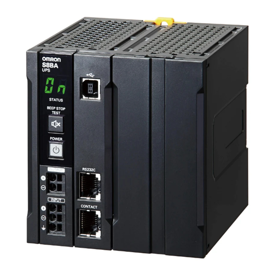
Uninterruptible Power Supply (UPS)
Integrated battery type
S8BA-LF
DC-DC type small UPS mounts on a
DIN rail to provide an ideal
countermeasure for momentary power
losses and power failures in industrial
computers (IPC) and controllers.
• System reliability greatly improved because
24VDC power supply is backed up for a certain
period of time in the event of voltage drop or power failure.
• Compactness, weight reduction, and long battery life
realized thanks to the adoption of a lithium-ion battery.
• Push-in terminal block adopted for the power input and
output I/F.
• Shutdown in conjunction with the industrial
purpose computer (IPC) or controller realized
by the USB/RS-232C/I/O port installed in the UPS.
Model Number Structure
Model Number Legend
S8BA- @@@@@@@@@LF
Series name
1
2
3
1. Input voltage specification
24D: 24 VDC
2. Output voltage
24D: 24 VDC
Ordering Information
Main body
Uninterruptible Power Supply (UPS)
Input voltage
Output voltage
24 VDC
24 VDC
* 16.7 A/400 W for use as a UL compliant device.
Communication cable
Specifications
For RS-232C port
RJ45/Dsub9Pin
For CONTACT port
RJ45/Discrete wire
Replacement battery pack
Rated voltage
Rated capacity
14.4 VDC
1600 mAh
* Use the following format to place an order.
3. Capacity
120: 120 W
240: 240 W
360: 360 W
480: 480 W
Output current/capacity
5 A/120 W
10 A/240 W
15 A/360 W
20 A/480 W *
Type
Length
2 m
Weight
0.3 kg
! Refer to Safety Precautions on page 13.
Model number
S8BA-24D24D120LF
S8BA-24D24D240LF
S8BA-24D24D360LF
S8BA-24D24D480LF
Model number
S8BW-C01
S8BW-C02
Model
UPS Model : Required units
S8BA-24D24D120LF : 1 pcs
S8BA-24D24D240LF : 2 pcs
S8BA-B120L
S8BA-24D24D360LF : 3 pcs
S8BA-24D24D480LF : 4 pcs
1
Advertisement
Table of Contents

Related Manuals for Omron S8BA LF Series


Summary of Contents for Omron S8BA LF Series
- Page 1 Uninterruptible Power Supply (UPS) Integrated battery type S8BA-LF DC-DC type small UPS mounts on a DIN rail to provide an ideal countermeasure for momentary power losses and power failures in industrial computers (IPC) and controllers. • System reliability greatly improved because 24VDC power supply is backed up for a certain period of time in the event of voltage drop or power failure.
- Page 2 S8BA-LF Ratings, Characteristics, and Functions Item Capacity 120 W 240 W 360 W 480 W *4 Rated input voltage 24 VDC When standard voltage 24 VDC±10% sensitivity is set Input When low voltage sensitivity voltage 24 VDC±12.5% is set range When high voltage 24 VDC±5% sensitivity is set...
- Page 3 S8BA-LF Nomenclature Front view Enlarged view of the operation panel S8BA-24D24D120LF (120 W) S8BA-24D24D240LF (240 W) S8BA-24D24D360LF (360 W) S8BA-24D24D480LF (480 W) Name Function Operation panel Describe the name of each part. DC output terminal block Connect to load lines. (+V), (-V) DC input terminal block Connect to input lines.
-
Page 4: Rear View
S8BA-LF Rear view S8BA-24D24D120LF (120 W) S8BA-24D24D240LF (240 W) S8BA-24D24D360LF (360 W) S8BA-24D24D480LF (480 W) Name Function DIN rail mounting hook Hook the UPS on the DIN rail. DIN rail mounting groove Groove for positioning the DIN rail and the UPS. - Page 5 S8BA-LF Connections Block Diagrams S8BA-24D24D@@@LF Diagram of the Input/output circuit block 24 VDC 24 VDC Input Output Normal operation: ON Backup operation: OFF DC-DC converter Normal operation: OFF Normal operation: ON Backup operation: ON Backup operation: OFF Charge/Discharge Normal operation Backup operation Battery * In normal operation, 24 VDC is output as-is for charging the battery and from the input power supply.
-
Page 6: I/O Signal Functions
S8BA-LF I/O signal functions Type of output signals Signal Description Backup signal output (BU) Stays ON during backup operation at a power failure. Low battery level signal output (BL) Goes ON when the battery becomes weak during backup operation at a power failure. Trouble signal output (TR) Goes ON when an internal failure of the UPS occurs or when the battery life counter expires. - Page 7 S8BA-LF Contact signal circuit Signal output (BU, TR, BL, WB) Remote ON/OFF UPS Stop Signal input (BS) 680 Ω Remote ON/OFF (+) 4.7 Ω Remote ON/OFF (–) Precautions when selecting switch mode power supplies When selecting switch mode power supplies, install devices with a capacity larger than the total of the UPS internal power consumption and internal power consumption of connected devices to the input side of the UPS.
-
Page 8: Engineering Data
S8BA-LF Engineering Data Estimated backup time The backup time varies depending on the capacity of connected devices. After calculating the total capacity of connected devices, refer to the graph of the backup time to obtain an estimation of the initial value of the backup time. -
Page 9: Derating Curve
S8BA-LF Derating curve 120, 240 W 360 W 480 W <S8BA-24D24D120LF> <S8BA-24D24D360LF> <S8BA-24D24D480LF> <S8BA-24D24D240LF> Ambient temperature (°C) Ambient temperature (°C) Ambient temperature (°C) A: For standard mounting, face-up mounting, sta- A: For standard mounting, A: For standard mounting, tionary mounting B: For face-up mounting, stationary mounting B: For face-up mounting, stationary mounting C: For standard mounting (For use as a UL compli-... - Page 10 S8BA-LF When the input power supply recovers while the battery level is Low Input power supply During power failure Power switch High Battery level Empty UPS output Indication in the "status display" 0.2 s Beeper * Normal operation UPS operating mode Backup operation BU signal (OUT) BL signal (OUT)
- Page 11 S8BA-LF Overcurrent protection curve 120W, 240W, 360W, 480W * In backup operation 100 120 Output current (%) Note: 1. In backup operation, the output voltage drops at a load rate of 110% or higher. 2. In normal operation, the output stops when the input protection fuse blows out. Dimensions (Unit: mm) Main body...
-
Page 12: End Plate
S8BA-LF DIN Rail (Order Separately) Mounting Rail (Material: Aluminum) PFP-100N PFP-50N 7.3 ± 0.15 35 ± 27 ± 0.15 15(5) * 1,000 (500) * * Values in parentheses are for the PFP-50N. Mounting Rail (Material: Aluminum) PFP-100N2 35 ± 29.2 1,000 End Plate PFP-M... -
Page 13: Safety Precautions
• If you drop the unit, stop using it and have it inspected property damage. and repaired. Supplementary comments on what to Precautions For details on repair, contact the OMRON do or avoid doing to use the product representative. for Safe Use safely. - Page 14 S8BA-LF (for use) Do not exceed the ranges specified for environmental conditions during use/storage. Do not allow the unit to come in contact with water. If you Do not install or store the unit in the places listed below. • Do not store in places where the humidity is lower than drop the unit, stop using it.
-
Page 15: Precautions For Safe Use
S8BA-LF (for maintenance) Do not dispose of battery in a fire or damage battery. • The insulator inside the battery may melt, the gas When maintaining the connected equipment, turn OFF exhaust valve or protection mechanism may be the unit’s “Power” switch to stop the output, and stop the damaged, or the electrolyte may catch fire, and it may supply of the “input power supply”. -
Page 16: For Storage
S8BA-LF For Storage Face-up mounting To store the UPS for a long time, store it in an environment where the ambient temperature is 25°C or lower, and charge the battery once every year for 10 to 15 minutes. • The battery discharges itself even if it is not used. If the battery is left unused for a long time, it goes into a state of over-discharge. - Page 17 Directives will vary depending on the configuration, wiring, and other from you, ensure that its top side is not in conditions of the equipment or control panel on which the OMRON contact with wall. devices are installed. The customer must, therefore, perform the final...
-
Page 18: Fcc Caution
S8BA-LF Conformance to UL Conformance to UL • This product must be installed within a control panel with an internal heater or other unit to protect against the formation of condensation. • Gaps in the door to the control panel must be completely filled or covered with gaskets or other material. - Page 19 Uninterruptible Power Supply (UPS) Separated battery type S8BA-SBF DC-DC type small UPS mounts on a DIN rail to provide an ideal countermeasure for momentary power losses and power failures in industrial computers (IPC) and controllers. • System reliability greatly improved because 24VDC power supply is backed up for a certain period of time in the event of voltage drop or power failure.
-
Page 20: Ordering Information
S8BA-SBF Ordering Information Main body Uninterruptible Power Supply (UPS) / Control Unit Part Input voltage Output voltage Output current/capacity Model number 20 A/480 W S8BA-24D24D480SBF 24 VDC 24 VDC 40 A/960 W S8BA-24D24D960SBF Note: The control unit (960 W) and the battery unit (480 W) cannot be connected. Battery unit part Rated voltage Rated capacity... - Page 21 S8BA-SBF Ratings, Characteristics, and Functions Description Capacity 480 W 960 W Rated input voltage 24 VDC Input voltage range 23 to 28 VDC Input for rated input voltage maximum 21.5 A 43.5 A for rated loads connected DC input current Input terminal Push-in terminal block Input protection...
- Page 22 S8BA-SBF Description Capacity 480 W 960 W Remote ON/OFF signal logic setting; Battery life counter setting; Maximum backup time setting; Startup Accessory functions battery level setting; Backup stop (BS) signal delay time setting; and Backup (BU) signal delay time setting *1.
- Page 23 S8BA-SBF Nomenclature Front view S8BA-24D24D480SBF S8BA-S480L Positive terminal Negative terminal [DC ON] LED [BATT] LED [ALERT] LED Name Name DC input terminal block CONTACT port DC output terminal block Battery communication port Battery connection terminal block Mode selection / Backup time setting switch LED indicators RS232C / USB port S8BA-24D24D960SBF...
- Page 24 S8BA-SBF Rear view S8BA-24D24D480SBF S8BA-S480L Name DIN rail hook S8BA-24D24D960SBF S8BA-S960L Name DIN rail hook...
-
Page 25: Connecting A Cable To The Input Terminal Block And The Output Terminal Block
S8BA-SBF Connections Block Diagrams S8BA-24D24D@@@SBF Control unit 24 VDC 24 VDC Input Normal operation: ON Output Backup operation: OFF Charge Normal operation: ON Backup operation: OFF Battery unit Normal operation: OFF Backup operation: ON Battery Normal operation Backup operation Note: 1. In normal operation, 24 VDC is output as-is for charging the battery and from the input power supply. If the 24 VDC from the input power supply becomes lower, the operation automatically switches to backup operation, and 24 VDC is output from the battery. - Page 26 S8BA-SBF I/O signal functions Type of output signals Signal Description Backup signal output (BU) Stays ON during backup operation at a power failure. Low battery level signal output (BL) Goes ON when the battery becomes weak during backup operation at a power failure. Trouble signal output (TR) Goes ON when an internal failure of the UPS occurs or when the battery life counter expires.
- Page 27 S8BA-SBF Contact signal circuit Signal output (BU, TR, BL, WB) Remote ON/OFF UPS Stop Signal input (BS) 3.3 V 220 Ω Remote ON/OFF (+) 100 Ω Remote ON/OFF (–) Precautions when selecting switch mode power supplies When selecting switch mode power supplies, install devices with a capacity larger than the total of the UPS internal power consumption and internal power consumption of connected devices to the input side of the UPS.
- Page 28 S8BA-SBF Engineering Data Estimated backup time The backup time varies depending on the capacity of connected devices. After calculating the total capacity of connected devices, refer to the graph of the backup time to obtain an estimation of the initial value of the backup time.
- Page 29 S8BA-SBF Derating curve Standard mounting (15 mm or more space Contact mounting (Less than 15 mm between the left and right) space between the left and right) Ambient temperature (°C) Ambient temperature (°C) Backup operation sequence in the event of power failure/voltage drop (instantaneous voltage drop) When the input power supply recovers while the battery level is sufficiently high Durling power failure Input power supply...
- Page 30 S8BA-SBF When the input power supply does not recover until the battery becomes empty Durling power failure Input power supply High Battery restorage Empty Output from UPS Normal operation operating Backup operation mode BU signal (OUT) * * BL signal (OUT) *...
- Page 31 S8BA-SBF Dimensions (Unit: mm) Control unit S8BA-24D24D480SBF 111.4 99.4 S8BA-24D24D960SBF 111.4 99.4 Battery unit S8BA-S480L 111.4 30.7 99.4 S8BA-S960L 111.4 30.7 99.4...
- Page 32 S8BA-SBF DIN Rail (Order Separately) Mounting Rail (Material: Aluminum) PFP-100N PFP-50N 7.3 ± 0.15 35 ± 27 ± 0.15 15(5) * 1,000 (500) * * Values in parentheses are for the PFP-50N. Mounting Rail (Material: Aluminum) PFP-100N2 35 ± 29.2 1,000 End Plate PFP-M...
- Page 33 S8BA-SBF Safety Precautions Warning Indications (When replacing the battery unit) Indicates a potentially hazardous Dispose of or collect (recycle) the battery unit according situation that, if not avoided, could to your own rules set for that purpose or as instructed by Warning result in serious injury or death.
- Page 34 S8BA-SBF Do not use the unit at a location where the operating Do not run this unit in parallel. • Operating this unit in parallel may cause a failure or environment temperature is more than 55°C • The battery deteriorates rapidly. It may result in fire. malfunction.
- Page 35 S8BA-SBF (for battery replacement) The unit is equipped with an output circuit that can supply power to the connected devices even if the unit stops due Do not use other than the designated battery unit. to a failure or mis-operation of the internal circuit function. •...
- Page 36 S8BA-SBF Correct Installation Method Precautions for Safe Use • For installation, to improve the long time reliability of the UPS, pay much attention to heat dissipation. Ensure convection of air around Before using the UPS main body, and use the UPS in an operating condition •...
- Page 37 • When replacing the battery unit, set the unit to "BATT REP" Directives will vary depending on the configuration, wiring, and other conditions of the equipment or control panel on which the OMRON (Battery unit replacement mode) using the mode selection / backup devices are installed.
- Page 38 S8BA-SBF Conformance to EC Directives This product complies with EC Directives. To ensure that the machine or device in which the this product is used complies with EC Directives, the product must be installed as follows: • This product must be installed within a control panel. •...
-
Page 39: Terms And Conditions Agreement
Data presented in Omron Company websites, catalogs and other materials is provided as a guide for the user in determining suitability and does not constitute a warranty. It may represent the result of Omron’s test conditions, and the user must correlate it to actual application requirements. - Page 40 The Netherlands Hoffman Estates, IL 60169 U.S.A. Tel: (31)2356-81-300/Fax: (31)2356-81-388 Tel: (1) 847-843-7900/Fax: (1) 847-843-7787 © OMRON Corporation 2015-2018 All Rights Reserved. OMRON (CHINA) CO., LTD. OMRON ASIA PACIFIC PTE. LTD. In the interest of product improvement, Room 2211, Bank of China Tower, No.
Need help?
Do you have a question about the S8BA LF Series and is the answer not in the manual?
Questions and answers