
Subscribe to Our Youtube Channel
Related Manuals for Omron S8BA-24D24D960SBF


Summary of Contents for Omron S8BA-24D24D960SBF
- Page 1 Uninterruptible Power Supply (UPS) S8BA-24D24D□□□SBF Control Unit S8BA-S□□□L Battery Unit User's Manual S8BA-24D24D480SBF S8BA-S480L S8BA-24D24D960SBF S8BA-S960L...
-
Page 2: Introduction
Introduction Introduction Thank you for purchasing OMRON's Uninterruptible Power Supply (UPS). This manual contains information that is necessary to use the “Uninterruptible Power Supply (UPS)”. Read this manual carefully and make sure that you understand the functionality and performance of the product before using it in your system. -
Page 3: Manual Structure
Manual Structure Manual Structure Page Structure and Icons The following page structure and icons are used in this manual. Level 1 heading 4 Installation and Wiring Level 2 heading Level 3 heading Mounting Units Level 2 heading Gives the current Level 3 heading headings. - Page 4 Manual Structure Special Information Special information in this manual is classified as follows: Precautions for Safe Use Precautions on what to do and what not to do to ensure safe usage of the product. Precautions for Correct Use Indicates the items to be implemented or avoided when the product is not operating, or to pre- vent a negative impact on the performance and functions.
- Page 5 Manual Structure S8BA Series Uninterruptible Power Supply (UPS) User’s Manual (U726)
- Page 6 Table of Contents Table of Contents Overview of the product Appendix Preparation Installation and connection Operations Maintenance and inspection To perform shutdown processing of the devices when a power failure occurs Using the I/O signal functions Troubleshooting S8BA-series Uninterruptible Power Supply (UPS) User’s Manual (U726)
-
Page 7: Table Of Contents
CONTENTS CONTENTS Introduction ......................1 Manual Structure...................... 2 Table of Contents ..................... 5 Terms and Conditions Agreement ................. 8 Safety precautions....................10 Regulations and standards................... 17 Revision History..................... 19 Section 1 Overview of the product Features of this product ....................... 1-2 Specifications ........................ - Page 8 CONTENTS Section 5 Maintenance and inspection Inspecting the battery ......................5-2 5-1-1 Expectancy of the battery ......................5-2 5-1-2 Estimated backup time ....................... 5-2 Replacing the battery unit ....................5-4 5-2-1 Notification that the battery unit needs to be replaced..............5-4 5-2-2 Procedure for replacing the battery unit..................
-
Page 9: Terms And Conditions Agreement
Omron’s exclusive warranty is that the Products will be free from defects in materials and workman- ship for a period of twelve months from the date of sale by Omron (or such other period expressed in writing by Omron). Omron disclaims all other warranties, express or implied. - Page 10 Disclaimers Performance Data Data presented in Omron Company websites, catalogs and other materials is provided as a guide for the user in determining suitability and does not constitute a warranty. It may represent the result of Omron’s test conditions, and the user must correlate it to actual application requirements. Actual perfor- mance is subject to the Omron’s Warranty and Limitations of Liability.
-
Page 11: Safety Precautions
Safety precautions Safety precautions Important information for safe operation is described. Be sure to read it before installation and start of use. The safety symbols and their meaning used in this manual are as follows: If you fail to use the product properly, it may result in injuries, mild or moderate, and may lead to death. - Page 12 Safety precautions Warning WARNING For use of this product • Provide safety measures outside the UPS to ensure safety in the entire system even if the UPS is damaged or an abnormality occurs due to an external factor. Not doing so may result in serious accidents due to incorrect operation.
- Page 13 Safety precautions Be sure to connect the input power supply of the unit to a DC power supply device having a rated voltage (24 VDC), or a battery power feed system. • The input voltage ranges for the UPS are as shown below. Check that the output voltage of the DC power supply device connected to the input terminal of the UPS is within any of the voltage ranges below.
- Page 14 Safety precautions Do not use a cable with damaged insulation. Do not pinch or sharply bend the cable. Do not fold or knot the cable. • Doing so may cause the cable to be damaged or heated, which may cause an electric shock or a fire.
- Page 15 Safety precautions Occasionally, wipe off dust on the input terminal block and the output terminal block with a dry cloth. • Accumulated dust may cause a fire. Before wiping off dust, stop all connected devices and the unit, and stop the supply of com- mercial power.
- Page 16 Safety precautions Do not throw the unit into fire. • Since the battery is incorporated in the unit, the insulator may melt, the gas exhaust valve or protection mechanism may be damaged, or the electrolyte may catch fire, and it may result eventually in an abnormal heating, smoke, rupture or fire.
- Page 17 Safety precautions Important Safety Points ■ Before using • The battery has not been charged at the time of purchase. Be sure to charge it before use. • Connect this unit to the input power supply to charge the battery unit. When moving the unit from a cold place to a warm place, leave it for several hours before using it.
-
Page 18: Regulations And Standards
• EMC Directives Principles regarding conformance OMRON electronic devices that comply with EC Directives also conform to the related EMC stan- dards so that they can be more easily built into other devices or the overall machine. The actual products have been checked for conformity to EMC standards Whether the products conform to the standards in the system used by the customer, however, must be checked by the customer. - Page 19 Regulations and standards • Surrounding Air Temperature, 55°C. • Make sure to connect the device with Class 2 output to the USB port. Conformance to FCC • FCC CAUTION Changes or modifications not expressly approved by the party responsible for compliance could void the user’s authority to operate the equipment.
-
Page 20: Revision History
Revision History Revision History A manual revision code appears as a suffix to the catalog number on the front and back covers of the manual. U726-E1-01 Revision code Revision Date Revised content code March 2018 Original production S8BA-series Uninterruptible Power Supply (UPS) User’s Manual (U726) - Page 21 Revision History S8BA-series Uninterruptible Power Supply (UPS) User’s Manual (U726)
-
Page 22: Overview Of The Product
Overview of the product This section describes the characteristics and specifications of the product. 1-1 Features of this product ........1-2 1-2 Specifications . -
Page 23: Features Of This Product
List of models The product has the following models: Unit model Specifications S8BA-24D24D480SBF Control unit (480 W) S8BA-24D24D960SBF Control unit (960 W) S8BA-S480L Battery unit (for 480 W) S8BA-S960L Battery unit (for 480 W / 960 W) Note The control unit (960 W) and battery unit (480 W) cannot be connected. -
Page 24: Specifications
1 Overview of the product Specifications Description Capacity 480 W 960 W DC input Rated input voltage 24 VDC Input voltage range 23 to 28 VDC Input maxi- for rated input voltage 21.5 A 43.5 A mum current for rated loads connected Input terminal Push-in terminal block Input protection... - Page 25 1 Overview of the product Description Capacity 480 W 960 W Structure Dimensions (W×H×D mm) 44 × 124 × 111.4 (UPS control 52 × 124 × 111.4 (UPS control unit 20 A) unit 40 A) 80 × 124 × 111.4 (battery unit 150 ×...
-
Page 26: Procedure From Installation To Operation
1 Overview of the product Procedure from installation to operation The procedure from installation to operation is shown below. Read “Safety Precautions” Start Page 10 Remove the product from the package and check the contents 2. Preparation Installation/connection Perform installation and connection 3. - Page 27 1 Overview of the product 1 - 6 S8BA-series Uninterruptible Power Supply (UPS) User’s Manual (U726)
-
Page 28: Preparation
Preparation This section describes the preparations for using the product. 2-1 Unpacking the product ......... 2-2 2-2 Checking the contents . -
Page 29: Unpacking The Product
2 Preparation Unpacking the product Open the package box and take out the control unit, battery unit, and accessories. Caution Carry the unit considering its weight and balance, and place it on a stable and robust base. • If you drop the unit, the protection mechanism inside the battery unit may be broken, and it may result eventually in a fluid leak, abnormal heating, smoke, rupture, or fire. -
Page 30: Checking The Contents
2 Preparation Checking the contents Check whether all the package contents are included and there is no damage found on their appear- ance. If you should notice defects or anything wrong, contact our sales personnel. Accessories related to the control unit Description Quantity Instruction manual... -
Page 31: Name Of Each Part
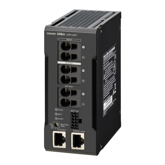
(2) DC output terminal block (6) Battery communication port (3) Battery connection terminal block (7) Mode selection / Backup time setting switch (4) LED indicators (8) RS232C/USB port S8BA-24D24D960SBF S8BA-S960L Positive terminal Negative terminal [DC ON] LED [BATT] LED [ALERT] LED... -
Page 32: Rear View
2 Preparation Rear view S8BA-24D24D480SBF S8BA-S480L (9) DIN rail stopper S8BA-24D24D960SBF S8BA-S960L (9) DIN rail stopper 2 - 5 S8BA-series Uninterruptible Power Supply (UPS) User’s Manual (U726) -
Page 33: Diagram Of The Input/Output Circuit Block
2 Preparation Diagram of the Input/output circuit block Control unit 24 VDC 24 VDC Input Normal operation: ON Output Backup operation: OFF Charge Normal operation: ON Backup operation: OFF Battery unit Normal operation: OFF Backup operation: ON Battery Normal operation Backup operation Note 1. -
Page 34: Installation And Connection
Installation and connection This section describes how to install and connect the product. 3-1 Installation ........... 3-2 3-1-1 DIN rail installation . -
Page 35: Installation
3 Installation and connection Installation This section describes how to install the UPS. For details on the precautions during installation, refer to For installation and connection on page 11. The UPS permits the following installing methods. Choose the one best suited for the environment. Precautions for Safe Use Before installing this device, make a record of the serial number of this device. - Page 36 3 Installation and connection Incorrect positions Mount UPS upside down DIN rail is placed vertically Bottom mounting Stack the units Reverse the left/right positions of the battery unit and control unit 3 - 3 S8BA-series Uninterruptible Power Supply (UPS) User’s Manual (U726)
-
Page 37: Din Rail Installation
3 Installation and connection 3-1-1 DIN rail installation Lower the rail stopper until you hear a click, and hook part A on one end of the rail. DIN rail DIN rail Push the rail stopper in the B direction, and then raise and lock it. Additional Information When removing, insert the flat blade screwdriver in the C part and pull it out. -
Page 38: Connection
3 Installation and connection Connection This section describes how to connect the UPS. For details on the precautions during connection, refer to For installation and connection on page 11. 3-2-1 UPS connection order Connections to the UPS must be made in the following order: Connect the control unit and the battery unit with a battery connection cable. -
Page 39: Connecting The Ups Control Unit And Battery Unit With A Battery Connection Cable
3 Installation and connection 3-2-2 Connecting the UPS control unit and battery unit with a battery connection cable Install the UPS control unit and battery unit on a DIN rail. For details, refer to 3-1-1 DIN rail installation on page 3-4. Insert the cables in the UPS control unit and battery unit in the following order: For details about connecting the cables to the terminal block, refer to 3-2-5 Connecting a cable to the battery terminal block, input terminal block and output terminal block on page 3-9. - Page 40 3 Installation and connection (5) Battery communication cable UPS control unit side (6) Battery communication cable Battery unit side Connect devices you want to back up to the output terminal block of the control unit. Connect the DC power supply device to the input terminal block of the control unit. 3 - 7 S8BA-series Uninterruptible Power Supply (UPS) User’s Manual (U726)
-
Page 41: Connecting A Device To The Output Terminal Block
3 Installation and connection 3-2-3 Connecting a device to the output terminal block Connect devices you want to back up to output terminals of this unit. For details about connecting the cables to the terminal block, refer to 3-2-5 Connecting a cable to the battery terminal block, input terminal block and output terminal block on page 3-9. -
Page 42: Connecting A Cable To The Battery Terminal Block, Input Terminal Block And Output Terminal Block
3 Installation and connection Precautions for Safe Use Note that the battery has not been charged. Charge the battery when you use the UPS for the first time. 3-2-5 Connecting a cable to the battery terminal block, input terminal block and output terminal block For details about the connectable sizes and recommended cable sizes, see the following table. - Page 43 3 Installation and connection Applicable wire Insulation Recommended ferrule terminals Ferrule stripping mar- conductor gin [mm] Manufactured Manufactured Manufactured by length (when using (AWG) by Phoenix by Widemüller WAGO (mm) ferrule termi- Contact nals) AI4.0-12 GY H4.0/20D FE-4.0-12N-GY AI6.0-12 YE H6.0/20 FE-6.0-12N-YE AI10-12 RD...
- Page 44 3 Installation and connection With the tip of the flat blade screwdriver in the hole, insert a cable into a round hole at the left of the terminal block. Pull out the flat blade screwdriver. Then, the cable is locked. Removing a connected cable from the terminal block Insert the tip of a flat blade screwdriver with a 3 mm or less thin blade into a square hole at the right of the terminal block and pull out the cable.
- Page 45 3 Installation and connection 3 - 12 S8BA-series Uninterruptible Power Supply (UPS) User’s Manual (U726)
- Page 46 Operations This section describes the operations of the product. 4-1 Checking the operation ......... 4-2 4-1-1 LED display .
-
Page 47: Checking The Operation
4 Operations Checking the operation 4-1-1 LED display Types of LEDs Output LED (Green) Indicates the unit output status. Battery LED (Yellow) Displays the status of the battery. Error LED (Red) Displays the error status of the unit. Operation of the LED Blinking ( 200 mS 200 mS... - Page 48 4 Operations Concept of LED display : Steadily ON : Blink : OFF LED display Charge Input [DC ON] [BATT] [ALERT] /Dis- power Description Procedures output charge supply (Green) (Yellow) (Red) No DC input. Operation paused. Charge DC input. Operating normally. Charging.
- Page 49 4 Operations LED display Charge Input [DC ON] [BATT] [ALERT] /Dis- power Description Procedures output charge supply (Green) (Yellow) (Red) Charge Battery not connected or Replace the battery unit. By incorrectly connected, or purchasing a new battery battery life counter counted unit, you (the customer) can Blink 2 Blink 2...
-
Page 50: Backup Operation Time Setting / Battery Replacement Mode Selection Switch
4 Operations 4-1-2 Backup operation time setting / Battery replacement mode selec- tion switch Switching to the backup operation time setting / Battery replacement mode Sets the backup operation time. For the setting, use a 2.5 mm or less flat-head screwdriver. Set value Description SV FREE... -
Page 51: Start And Stop Procedures And Basic Operation
4 Operations Start and stop procedures and basic operation 4-2-1 Start and stop procedures For details on the precautions for use, including start and stop of the product, refer to For use on page 13. Start procedure Connect the unit to the input power supply. •... - Page 52 4 Operations The backup sequence when power failure/voltage drop (instanta- neous voltage drop) occures Explains the backup sequence when a power failure occurs. When the input power supply recovers while the battery level is sufficiently high Durling power failure Input power supply High Battery restorage Empty...
- Page 53 4 Operations For shutdown by a BS signal Durling power failure Input power supply High Battery restorage Empty Output from UPS Normal operation operating mode Backup operation BU signal (OUT) BL signal (OUT) BS signal (IN) *1. For details, refer to 7-1 I/O signal functions on page 7-2. Input and output voltage time chart when shifting to backup opera- tion Explains the operation when shifting to backup operation due to power failure or input voltage drop.
- Page 54 4 Operations Operation after a power failure If a power failure or input power supply error occurs, the operation automatically switches to backup operation to continue the power output by using electrical power from the battery. : Steadily ON : Blink : OFF LED display [DC ON]...
- Page 55 4 Operations 4 - 10 S8BA-series Uninterruptible Power Supply (UPS) User’s Manual (U726)
-
Page 56: Maintenance And Inspection
Maintenance and inspection This section describes how to perform maintenance of this product and also how to replace the battery unit. 5-1 Inspecting the battery ......... . 5-2 5-1-1 Expectancy of the battery . -
Page 57: Maintenance And Inspection
5 Maintenance and inspection Inspecting the battery The battery has a limited lifespan. (The life varies depending on your storage/use environment and backup frequency.) The nearer the end of the life is, the more rapidly deterioration proceeds. Caution For details on the precautions when performing maintenance, refer to For maintenance on For maintenance page 10. - Page 58 5 Maintenance and inspection S8BA-24D24D960SBF S8BA-S960L S8BA-24D24D480SBF S8BA-S960L S8BA-24D24D480SBF S8BA-S480L 60 120 180 240 300 360 420 480 540 600 660 720 780 840 900 960 1020 Capacity (W) Backup time table (Time unit: minutes) Capacity (Watt) Model 90 120 180 240 300 360 420 480 540 600 660 720 780 840 900 960...
-
Page 59: Replacing The Battery Unit
5 Maintenance and inspection Replacing the battery unit This UPS supports hot swapping. The battery unit can be replaced both when the power is turned OFF (while the power output is OFF) and when the power is turned ON (while the power output is ON). Caution For details on the precautions for maintenance, refer to For maintenance on page 14 and When the Battery Unit is Replaced on page 15... -
Page 60: Battery Life Counter Function
5 Maintenance and inspection Battery Life Counter Function The function that counts the battery unit energization time and notifies the user when it is time to replace the battery unit is called the battery life counter function. The UPS measures the ambient temperature at every 8 hours and adds the counter value according to the measured temperature. -
Page 61: Procedure For Replacing The Battery Unit
5 Maintenance and inspection 5-2-2 Procedure for replacing the battery unit For details on the precautions to be taken when replacing the battery unit, refer to When the Battery Unit is Replaced on page 15 in the "Safety precautions" at the beginning of this manual. Precautions for Safe Use Be sure to activate the battery replacement mode before replacing the battery unit. - Page 62 5 Maintenance and inspection Pull out the cables from the old battery unit in the following order: For details about the method of connecting cables to the terminal block, refer to 3-2-5 Connecting a cable to the battery terminal block, input terminal block and output terminal block on page 3-9" (1) Battery communication cable (2) BATT connection cable Negative side...
- Page 63 5 Maintenance and inspection Insert the cables in the new battery unit in the following order: For details about the method of connecting cables to the terminal block, refer to 3-2-5 Connecting a cable to the battery terminal block, input terminal block and output terminal block on page 3-9" (1) BATT connection cable Positive side (2) BATT connection cable...
-
Page 64: Cleaning The Unit
5 Maintenance and inspection Cleaning the Unit Caution For details on the precautions when performing maintenance, refer to For maintenance on For maintenance page 10. on page 14 Cleaning the UPS Moisten a soft cloth with water or detergent, squeeze it tightly, and wipe the product lightly. Do not use chemicals such as thinner and benzene. - Page 65 5 Maintenance and inspection 5 - 10 S8BA-series Uninterruptible Power Supply (UPS) User’s Manual (U726)
-
Page 66: To Perform Shutdown Processing Of The Devices When A
To perform shutdown processing of the devices when a power failure occurs This section describes how to use the UPS monitoring software. 6-1-1UPS monitoring software ........6-2 6-1-1 UPS monitoring software . -
Page 67: The Outline On The Ups Monitoring Software
6 To perform shutdown processing of the devices when a power failure occurs The outline on the UPS monitoring software 6-1-1 UPS monitoring software "Simple Shutdown Software" or "PowerAttendant Lite" allows you to automatically shut down the PC when a power failure occurs. For more information, refer to the manual of this software. - Page 68 6 To perform shutdown processing of the devices when a power failure occurs ● Cable pin configuration • Using an RS-232C cable [UPS side] [PC side] RJ45 S8BW-C01 Dsub-9pin Name Connection Name • Using a USB cable [UPS side] [PC side] RJ45 USB cable Name...
- Page 69 6 To perform shutdown processing of the devices when a power failure occurs 6 - 4 S8BA-series Uninterruptible Power Supply (UPS) User’s Manual (U726)
-
Page 70: Using The I/O Signal Functions
Using the I/O signal functions This section describes the I/O signals of the product. 7-1 I/O signal functions ..........7-2 7-1-1 Type of output signals . -
Page 71: I/O Signal Functions
7 Using the I/O signal functions I/O signal functions About contact signal You can develop your unique system based on the following specifications to automate the process at a power failure. You can perform power-failure processing by allowing the system to detect the backup signal (BU) and also perform system shutdown processing by allowing the system to detect the low battery level signal (BL). -
Page 72: Contact Port (Rj45 Connector)
7 Using the I/O signal functions 7-1-3 CONTACT port (RJ45 connector) Outlook of the Cable color Description connector number White/orange Backup signal output (BU) Orange Remote ON/OFF input (-) White/green Trouble signal output (TR) Blue COMMON (COM) White/blue Battery LOW signal output (BL) Green Backup stop signal input (BS) Pin number8... -
Page 73: Precautions And Notes For The Use Of The I/O Signal Functions
7 Using the I/O signal functions 7-1-6 Precautions and notes for the use of the I/O signal functions Precautions for Safe Use When connecting a device such as a relay that generates counter electromotive force to the signal output circuit, connect diodes that prevent counter electromotive force to both ends of the relay. -
Page 74: Troubleshooting
Troubleshooting This section describes how to check and handle errors that occur at the time of using the product. 8-1 Troubleshooting ..........8-2 8 - 1 S8BA-series Uninterruptible Power Supply (UPS) User’s Manual (U726) - Page 75 8 Troubleshooting Troubleshooting Perform the checks shown below if the unit is operating abnormally. Problem Check and remedy The unit does not start operation. Make sure the AC input is securely connected to commercial power. There is no LED display even If the status indicator does not display properly after you perform the above when the unit is connected to the operation, there is a problem with the unit.
-
Page 76: Appendix
Appendix This section describes the dimensions and characteristic data of the product. A-1 Dimensions ........... A-2 A-2 Characteristic data . -
Page 77: A-1 Dimensions
A-1 Dimensions S8BA-24D24D480SBF Note Unit: mm / Tolerance:±1mm 111.4 S8BA-S480L Note Unit: mm / Tolerance:±1mm 111.4 A - 2 S8BA-series Uninterruptible Power Supply (UPS) User’s Manual (U726) - Page 78 S8BA-24D24D960SBF Note Unit: mm / Tolerance:±1mm 111.4 S8BA-S960L Note Unit: mm / Tolerance:±1mm 111.4 A - 3 S8BA-series Uninterruptible Power Supply (UPS) User’s Manual (U726)
- Page 79 Optional items for rail mounting Support rail (Alminum) PFP-100N PFP-50N ± 0.15 ± 0.3 ± 0.15 15 25 15 (5) 1,000(500) * PFP-50N dimensions are given in parentheses. Support rail (Alminum) PFP-100N2 29.2 ± 0.3 15 25 25 15 1,000 Fastening plate (End plate) PFP-M M4×8...
-
Page 80: A-2 Characteristic Data
A-2 Characteristic data A-2-1 Derating curve Standard mounting (15 mm or more space between the left and right) Operating temperature (°C) Contact mounting (less than 15 mm space at the left and right) Operating temperature (°C) A - 5 S8BA-series Uninterruptible Power Supply (UPS) User’s Manual (U726) -
Page 81: A-2-2 Overcurrent Protection Curve
A-2-2 Overcurrent protection curve 480W/960W 111% Load ratio (%) A - 6 S8BA-series Uninterruptible Power Supply (UPS) User’s Manual (U726) - Page 82 The Netherlands Hoffman Estates, IL 60169 U.S.A. Tel: (31)2356-81-300/Fax: (31)2356-81-388 Tel: (1) 847-843-7900/Fax: (1) 847-843-7787 © OMRON Corporation 2015-2018 All Rights Reserved. OMRON (CHINA) CO., LTD. OMRON ASIA PACIFIC PTE. LTD. In the interest of product improvement, Room 2211, Bank of China Tower, No.
Need help?
Do you have a question about the S8BA-24D24D960SBF and is the answer not in the manual?
Questions and answers