Omron S8T-DCBU-01 Manual
Dc backup block
Hide thumbs
Also See for S8T-DCBU-01:
- Brochure & specs (6 pages) ,
- Manual (20 pages) ,
- Manual (16 pages)
Table of Contents
Advertisement
Quick Links
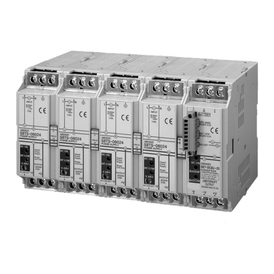
DC Backup Block for S8TS
S8T-DCBU-01
DC Backup Block for S8TS
for Preventing 24 VDC Outages due to
Instantaneous Power Failures
• Supplies 24 VDC for a fixed period of time even during
AC input outages to considerably improve system reliability.
• Block Power Supply Basic Block is connected by the Bus Line
Connector.
Simple system configuration
• Alarms are notified by indication on main unit and by alarm
signal output.
Ordering Information
DC Backup Block (See note 1.)
Output voltage
24 V
Note: 1. One S8T-BUS03 Connector is included as an accessory.
2. The output current can be selected by a switch.
Bus Line Connector
Type
DC line bus
Note: One package contains 10 S8T-BUS03 Connectors.
Battery Holder
Model number
S82Y-TS01
Basic Block
Screw terminal type
Connector terminal type
Note: Use S8T-DCBU-01 in a pair with the Block Power Supply Basic Block.
3.7 A/ 8 A (See note 2.)
Number of Connectors
1 Connector
10 Connectors (See note.)
Type
With Bus Line Connectors
Without Bus Line Connectors
With Bus Line Connectors
Without Bus Line Connectors
Block Power Supply Basic Block
Output current
Output voltage/Output current
24 V/ 2.5 A
DC Backup Block for S8TS
DC Backup Block
Model number
S8T-DCBU-01
Model number
S8T-BUS03
S8T-BUS13
Model number
S8TS-06024-E1
S8TS-06024
S8TS-06024F-E1
S8TS-06024F
S8T-DCBU-01
1
Advertisement
Table of Contents

Related Manuals for Omron S8T-DCBU-01


Summary of Contents for Omron S8T-DCBU-01
- Page 1 24 V/ 2.5 A S8TS-06024-E1 Without Bus Line Connectors S8TS-06024 Connector terminal type With Bus Line Connectors S8TS-06024F-E1 Without Bus Line Connectors S8TS-06024F Note: Use S8T-DCBU-01 in a pair with the Block Power Supply Basic Block. S8T-DCBU-01 DC Backup Block for S8TS...
-
Page 2: Basic Configuration
Note: 1. The designated battery is made by Matsushita (Panasonic). 2. The designated battery is rated at 12 V. Use two batteries in series. 3. S8T-DCBU-01 shall be connected with S8TS-06024@ when in use. 4. Consult Panasonic representative when purchasing batteries. -
Page 3: Specifications
9. To be compliant with UL508 (Class2: per UL1310), take one of following each measure. Note that the number of S8TS-06024@ to be connected to the S8T-DCBU-01 shall be one. • Connect S8T-DCBU-01 to S82Y-TS01 having its fuse replaced with an UL-Listed and DC rated 32 VDC min./ 3 A max. one. -
Page 4: Block Diagram
Connections Block Diagram S8T-DCBU-01 Bypass D Battery − Discharge circuit Detection resistor Charging DC OUTPUT circuit Fuse −V 2.0 A Overdis- Overcurrent charge detection detection Operation Input Charging voltage mode control detection output circuit Battery voltage detection Battery Backup status... -
Page 5: Operation
Immediately eliminate the cause of the trouble. (Backup status indication, Operation mode output) S8T-DCBU-01 detects output voltage drop of S8TS-06024@ to 2. If switching between backup operation and Normal opera- switch to backup operation. -
Page 6: Stopping The Equipment
Use S8T-BUS03, which only DC lines are connected with. (AC line not connected). Connect S8T-DCBU-01 and the battery using a cable having a wire S8T-BUS03 is equipped with a selector for the prevention of errone- diameter specified in Recommended Wire Diameter (page 14)”... -
Page 7: Operation Check
Operation Check 4. Turn OFF the AC power of the S8TS-06024@. 5. Confirm that Backup operation is correctly performed in Status 2. After connecting S8TS-06024@ and S8T-DCBU-01, it is recom- Indicator Operation mode Battery status mended to check the DC Backup Block if it is correctly operating in... - Page 8 12 V battery). Activation of the erroneous battery connection function is notified in the following way. • LED (BAT LOW: Red) lights up. • Relay (BAT LOW) is in the LOW mode ((4)-(5): ON). S8T-DCBU-01 DC Backup Block for S8TS...
-
Page 9: Engineering Data
3. The peripheral temperature is specified at the place 50 mm downward from the main body of the DC Backup Block. 4. The operating temperature range of the battery is 0 to 40°C; it is different from that of S8T-DCBU-01. - Page 10 ((3)-(2)) ((6)-(5)) Note: Backup operation is not possible during the period (7 seconds (typical)) that the bat- ((4)-(5)) tery status output relay is LOW after the S8T-DCBU-01 is started up. Battery status output ((6)-(5)) Note: Backup operation is continued for seven seconds after the power is restored from a power failure.
-
Page 11: Battery Replacement
Replace the battery while referring to the following replacement (1) Turn the AC power line OFF, and back up the S8T-DCBU-01. period as a reference. (2) Measure the time that the battery status output relay turns to Note: 1. - Page 12 1,000 (500) * * Values in parentheses are for the PFP-50N. Mounting Track (Material: Aluminum) PFP-100N2 35 ± 29.2 1,000 End Plate PFP-M M4 × 8 pan-head screw 35.5 35.3 11.5 M4 spring washer S8T-DCBU-01 DC Backup Block for S8TS...
- Page 13 If malodor, abnormal noise, smoke or liquid is issued from the battery, turn off the switch of the Battery Holder. Continuation of operation in this state may cause fire. S8T-DCBU-01 DC Backup Block for S8TS...
- Page 14 Set the DC Backup Block as Connect the S8T-DCBU-01 to the right or left end of S8TS-06024@ far as possible from possible sources of shock or vibration. Addi- Basic Blocks.
-
Page 15: Troubleshooting
Troubleshooting This page lists the errors that may occur when the S8T-DCBU-01 is used, along with their probable causes and remedies. Check the relevant item. When Probable cause Description Remedies Installation S8T-DCBU-01 cannot be The Bus Line Connector is provided with a Set the selector on the Bus Line Connector connected. -
Page 16: Terms And Conditions Of Sale
Buyer indemnifies Omron against all related costs or expenses. rights of another party. 10. Force Majeure. Omron shall not be liable for any delay or failure in delivery 16. Property; Confidentiality. Any intellectual property in the Products is the exclu-... - Page 17 Complete “Terms and Conditions of Sale” for product purchase and use are on Omron’s website at www.omron247.com – under the “About Us” tab, in the Legal Matters section. ALL DIMENSIONS SHOWN ARE IN MILLIMETERS. To convert millimeters into inches, multiply by 0.03937. To convert grams into ounces, multiply by 0.03527.
Need help?
Do you have a question about the S8T-DCBU-01 and is the answer not in the manual?
Questions and answers