Table of Contents
Advertisement
Uninterruptible Power Supply
Instruction Manual
• This manual provides important safety-related information. Thoroughly read and understand
this manual before installing and using the product.
• Keep this manual in a convenient location so that you can refer to it whenever necessary.
• The contents of this manual are subject to change without notice.
BN50S/BN75S/BN100S
BN150S/BN220S/BN300S
Advertisement
Table of Contents

Subscribe to Our Youtube Channel
Related Manuals for Omron POWLI BN50S


Summary of Contents for Omron POWLI BN50S
- Page 1 Uninterruptible Power Supply BN50S/BN75S/BN100S BN150S/BN220S/BN300S Instruction Manual • This manual provides important safety-related information. Thoroughly read and understand this manual before installing and using the product. • Keep this manual in a convenient location so that you can refer to it whenever necessary. •...
- Page 2 Introduction Features of this product Thank you for purchasing Omron's Uninterruptible Power Supply (UPS). ● The UPS protects computers and other devices from power failures, voltage variations, in- stantaneous voltage drops, and surge voltage such as that caused by lightning (a phenom- enon in which extraordinary high voltage occurs instantaneously).
-
Page 3: Important Safety Instruction
IMPORTANT SAFETY INSTRUCTION 1. SAVE THESE INSTRUCTIONS. This manual contains important instructions for BN50S/BN75S/ BN100S/BN150S/BN220S/BN300S that should be followed when using the UPS and batteries. 2. SYMBOL This symbol indicates earth ground. This symbol indicates turning on UPS. This symbol indicates turning off UPS. 3. -
Page 4: Preparation For Operation
Procedure from installation to operation Read “Safety precautions” Start Page v Remove the product from the package and check the contents Page 1 Installation/connection Perform installation and connection Page 7 Are you Read “Using the UPS using UPS monitoring monitoring software and software or contact contact signal”... -
Page 5: Table Of Contents
Table of Contents Table of Contents Introduction IMPORTANT SAFETY INSTRUCTION ....................ii Safety precautions ..........................v 1. Preparation ............................1 1-1 Unpacking the product ......................... 1 1-2 Checking the contents .......................... 1 1-3 Name of each part ..........................2 1-4 Explanation of symbols used on unit ....................6 2. -
Page 6: Safety Precautions
S / BN S / BN S / BN S / BN S / BN Important information for safe operation is described. Safety precautions Be sure to read it before installation and start of use. ● The safety symbols and their meaning used in this manual are as follows: Warning Misuse may cause death or serious injury. - Page 7 Safety precautions Caution (for installation and connection) When an abnormality (unusual sound or smell) occurs, turn OFF the unit's power switch and disconnect the AC input plug from the wall outlet. Install the unit soon after the AC input plug is disconnected from the wall outlet.
- Page 8 S / BN S / BN S / BN S / BN S / BN Caution (for installation and connection) Do not pinch or tie the cable of the unit. ● Doing so may cause the cable to be damaged or heated, which may cause an electric shock or a fi re. ●...
- Page 9 ● Using the unit under such conditions may cause a fi re. ● Under such conditions, make sure to stop using the unit, unplug the AC input cable, and contact the shop of purchase or the OMRON Electronic Systems & Equipments Repair Center at __________ for inspection and repairs.
- Page 10 S / BN S / BN S / BN S / BN S / BN Caution (for maintenance) When maintaining the connected equipment, turn OFF the power switch and disconnect the AC input plug. ● Even if you disconnect the AC input plug while the UPS is operating, the power output of this unit does not stop and power is supplied from the outlet during a power failure.
- Page 11 Safety precautions Notes When moving the unit from a cold place to a warm place, leave it for several hours before using it. ● If the unit is promptly turned ON after being moved to a warmer place, condensation may form inside the unit and cause it to fail.
- Page 12 This unit uses lead acid batteries, ● Which are a valuable recyclable resource. Please recycle. ● For information about recycling, please contact the OMRON Electronic Systems & Equipments Repair Center at: __________. Explanation Usual operation ●...
-
Page 13: Preparation
User registration card 3P-2P conversion adapter None None Label (How to determine operat- ing status) Battery replacement date label Control panel English label Omron contact info label (2) UPS BN50S BN75S BN100S BN150S BN220S BN300S Quick installation guide... -
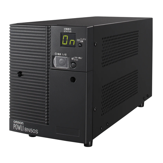
Page 14: Name Of Each Part
.Preparation Name of each part This section describes the name of each part of the UPS. For information on the function of each part, refer to "2. Installation and connection" on page 17 and "3. Operation" on page 34 that provides the details. Front view <BN50S/BN75S>... - Page 15 S / BN S / BN S / BN S / BN S / BN Side view <BN50S/BN75S> E. Air vent There are also air vents on the other side (right side of the unit). * The BN100S/BN150S/BN220S/BN300S does not have air vents on the sides.
-
Page 16: Rear View
.Preparation Rear view <BN50S/BN75S> <BN100S/BN150S> A. Signal card expansion slot B. Power supply output receptacles C. AC input cable D. Grounding terminal E. Input surge protection GND F. AC input overcurrent protection switch G. RS232C connector H. USB connector I. Setting switch J. - Page 17 S / BN S / BN S / BN S / BN S / BN Rear view <BN220S/BN300S> A. Power supply output receptacle A (NEMA5-20R) B. Power supply output receptacle B (NEMA5-15R) C. Power supply output receptacle C (NEMA5-15R) D. Power supply output receptacle A overcurrent protection switch 20A E.
-
Page 18: Explanation Of Symbols Used On Unit
.Preparation Explanation of symbols used on unit Symbol Description Start the UPS. Stop the UPS. Suspend a beep. Batteries at end of useful life, necessary to replace the batteries. -
Page 19: Installation And Connection
Installation and connection Precautions and notes on installation and connection Caution (for installation and connection) Two or more people should work together to carry, unpack and install the unit (BN100S/BN150S/BN220S/BN300S). ● Because the unit is heavy, you may injure yourself or drop the unit, or it may fall over. Carry the unit considering its weight and balance, and place it on a stable and robust base. - Page 20 .Installation and connection Caution (for installation and connection) Do not use the unit where the maximum temperature exceeds 40°C. ● The battery becomes weak rapidly, which may cause a fi re. ● Doing so may cause a failure or malfunction of the unit. Do not exceed the ranges specifi...
- Page 21 S / BN S / BN S / BN S / BN S / BN Notes When moving the unit from a cold place to a warm place, leave it for several hours before using it. ● If the unit is promptly turned ON after being moved to a warmer place, condensation may form inside the unit and cause it to fail.
- Page 22 .Installation and connection Notes Before stopping the commercial power to the unit, turn OFF the power switch of the unit. ● The unit enters Battery Mode when commercial power is stopped. If you frequently use the unit in Battery Mode, the battery life may be signifi cantly shortened. If this unit is used with an inductive device such as a coil or motor, check the operation beforehand.
-
Page 23: Installation And Connection
S / BN S / BN S / BN S / BN S / BN Installation and connection This section describes how to install the UPS. Do not use this unit in any position other than the “correct positions” indicated in the illustration below. Note Before installing this device, make a record of the unit’s serial number. -
Page 24: Connecting The Equipment
.Installation and connection Connecting the equipment Connecting a device to the power supply output (BN50S/BN75S/BN100S/BN150S) (1) Disconnect the AC Input Plugs of all devices you want Wall outlet to back up such as your PC and modems from a wall (commercial power) outlet (commercial power). - Page 25 S / BN S / BN S / BN S / BN S / BN Connecting a device to the power supply output (BN220S/BN300S) ● Group control of power supply output The output receptacles of the the UPS (BN220S/BN300S) are separated into 3 groups: A, B, and C. •...
- Page 26 .Installation and connection • When using a 2-pin input plug with a grounding wire, connect the grounding wire to earth in building. • When you want to use an AC adaptor, connect it to a Power Supply Output Receptacle of the UPS with space enough for the connection.
- Page 27 S / BN S / BN S / BN S / BN S / BN AC input plug The AC input plug for the BN150S/BN220S/BN300S can be changed according to the operating environment. The table below lists the AC input plugs provided at shipment and those that can be replaced, and it shows the maximum output capacity for each plug.
- Page 28 .Installation and connection AC input plug replacement procedure N: White 1. Disconnect the plug to be replaced. L: Black 2. Connect the replacement plug as shown in the diagram on the right. Connect the black wire to the L pole, the white wire to the N pole, and the green wire to the FG pole.
-
Page 29: Checking The Operation
S / BN S / BN S / BN S / BN S / BN Checking the operation After you fi nish connecting devices to the unit, make sure the backup function operates properly. Check that the Battery Mode is performed normally according to the following procedure. (This operation check simulates a power failure by disconnecting the AC input plug from a wall outlet.) (1) Turn ON the unit's power switch. - Page 30 .Installation and connection (5) In Battery Mode, check the unit's LED display and beep sound. Does the status indicator appear as one of those shown below? indicates blinking) Status indicator Beep Output Charging Description Intermittent Backup is operating due to power failure or AC input 4-second Discharging error.
-
Page 31: Charging The Battery
S / BN S / BN S / BN S / BN S / BN Charging the battery When you connect the AC input plug of this unit to a wall outlet (commercial power), the bat- tery charging automatically starts regardless of whether the power switch is ON or OFF, and it is fully charged within 8 hours. -
Page 32: Operation
● Using the unit under such conditions may cause a fi re. ● If the unit becomes wet, immediately stop using it, unplug the AC input cable, and contact the shop of purchase or the OMRON Electronic Systems & Equipments Repair Center at __________ for inspection and repairs. - Page 33 S / BN S / BN S / BN S / BN S / BN Notes Before stopping the commercial power to the unit, turn OFF the power switch of the unit. ● The unit enters Battery Mode when commercial power is stopped. If you frequently use the unit in Bat- tery Mode, the battery life may be signifi...
-
Page 34: Start And Stop Procedures And Basic Operation
.Operation Start and stop procedures and basic operation ● When the power switch is OFF and the AC input plug is connected to a commercial power supply: • The details of the most recent error are displayed. (item 4 on page 26) •... - Page 35 S / BN S / BN S / BN S / BN S / BN ● Operation after a power failure • If a power failure or abnormal input power supply occurs, the UPS automatically switches to Battery Mode, continuing power output from the Power Supply Output Receptacles supplied from the battery.
- Page 36 .Operation ● Operation during recovery from a power failure • If a power failure or abnormal power input is resolved while the UPS supplies power, it returns to the commercial power output status automatically. Charging the consumed battery starts. • If a power failure or abnormal power input is resolved after the battery is discharged complete- ly and power output is stopped, the UPS restarts automatically and resumes power output.
-
Page 37: Interpreting Beeps And Displays
S / BN S / BN S / BN S / BN S / BN Interpreting beeps and displays indicates the display is OFF) indicates the display is ON) 1. Displays and beeps in normal operation indicates blinking) Battery Status replacement Beep Output... - Page 38 .Operation 4. Displays and beeps when there is an equipment failure indicates the display is OFF) indicates the display is ON) indicates blinking) Battery Status replacement Beep Output Charging Description Solution indicator lamp There are too many connected devices and the rated capacity is exceeded If this state continues for as long as or longer than the times described...
- Page 39 S / BN S / BN S / BN S / BN S / BN 5. Display and beep for battery replacement indicates the display is OFF) indicates the display is ON) indicates blinking) Battery Status replacement Beep Output Charging Description Solution indicator...
-
Page 40: Ups Functions
UPS functions Suspending a beep When the beep is sounding, you can suspend it by pressing and holding the beep stop/test switch for 0.5 seconds or longer. Self-diagnosis test This test performs a failure diagnosis on the unit and performs a simple test to check for battery dete- rioration. -
Page 41: Description Of The Auto Battery Test Function
S / BN S / BN S / BN S / BN S / BN Description of the auto battery test function This test performs a failure diagnosis on the unit and performs a test to check for battery deteriora- tion. - Page 42 .UPS functions ● Setting for beeper sound in the event of power failure, etc. (setting switch 1 ) … Factory setting: OFF OFF: The beeper sounds when an alarm is necessary. The beeper does not sound for backup operation or battery replacement. The beeper sounds for other errors (connection capacity exceeded, operation error, etc.).
- Page 43 S / BN S / BN S / BN S / BN S / BN ● Auto startup mode setting (setting switch 4 ) … Factory setting: OFF OFF: (Mode A) After UPS stopped, the UPS is automatically started immediately when “ON” is detected for the AC input.
- Page 44 .UPS functions (2) When BS signal is used to shut down the UPS when AC input is ON 1 sec AC input Starts up when BS signal turns OFF BS signal Power output (Setting switch 4 OFF: Starts up when AC input Mode A) turns from OFF to ON Power output...
- Page 45 S / BN S / BN S / BN S / BN S / BN ● AC input plug selection (setting switch 7 , 8 ) … Factory setting: Refer to the table below. (The values may vary depending on the model.) * Always use the BN50S/BN75S/BN100S with the switches in their original OFF/OFF state (factory settings).
- Page 46 .UPS functions 2. UPS operation mode settings 2-1 Settable items and explanations There are 5 items to select. 1) Cold start ON/OFF setting 2) Input power sensitivity setting 3) Output voltage setting 4) Power output stop delay time setting * 5) Signal input/output test * * Can be used when the SC07 (option) is added.
- Page 47 S / BN S / BN S / BN S / BN S / BN 3) Output voltage setting (100V/115V) Two types of output voltage can be set. (Setting range: 100V/115V) Output is performed at the set voltage, with no relation to the input voltage. 4) Power output stop delay time setting It is possible to set the delay time for stopping the power supply output after the BS signal is received.
- Page 48 .UPS functions 5) Signal input/output test (BL/TR/BU/WB/BS/remote) ● Four types of output signal can be forcibly turned ON. ● The ON/OFF state of two types of input signal can be checked with the status indicator and the beeper. Signal input/output test end Signal input test While the signal is being Signal input/output test start...
- Page 49 S / BN S / BN S / BN S / BN S / BN 2-2 Settings The UPS operation mode can be set if the power switch is turned ON while the beeper stop /test switch is pressed. Note: While in setting mode, output from the power supply output is OFF even if the power switch is ON.
- Page 50 .UPS functions Turn ON the power switch while the beep stop/test switch is pressed. Normal status There is AC input Turn OFF the power switch. Power switch “OFF” (Status No. 2) Press and hold the beep stop/test switch (for more than 3 seconds). Press the beep stop/test switch (for less than 3 seconds).
-
Page 51: Measuring The Backup Time
Measuring the backup time How to measure backup time (1) When the AC input plug is connected to a wall outlet (commercial power), the battery automati- cally starts charging, taking up to 8 hours to complete. (2) Turn ON all devices connected to the power output to be “backed up during a power failure”. (This includes devices connected to the AC outlet of your computer.) Operate the connected devices in a way that allows the power supply to be stopped at any time. - Page 52 .Measuring the backup time (2) Add the values converted into W to obtain the total capacity of the connected devices. (3) Calculate the initial value of the backup time for the total capacity of the connected devices from the graph below. ●...
-
Page 53: Maintenance And Inspection
Maintenance and Inspection Caution (for maintenance) When maintaining the connected equipment, turn OFF the power switch and disconnect the AC input plug. ● Even if you disconnect the AC input plug while the UPS is operating, the power output of this unit does not stop and power is supplied from the outlet during a power failure. -
Page 54: Replacing The Battery
.Maintenance and Inspection 3. Guidelines for how often to check the battery (measure the backup time) Ambient temperature Check once every 6 months Check once a month 20°C For the fi rst 3 years after purchase When 3 or more years have passed since purchase 30°C For the fi... - Page 55 S / BN S / BN S / BN S / BN S / BN Battery recycling The unit uses lead acid batteries, which are a valuable recyclable resource. Please recycle. For information on recycling, please contact our Electronic Systems & Equipments repair center. ■...
- Page 56 .Maintenance and Inspection ➀ Turn the 2 screws that fi x the plate cover counter-clockwise to remove them. ➁ ➂ Pull the plate cover towards you and lift it up to remove it. Remove the 2 screws. Hold the pullout label at the bottom of the battery pack and remove the battery pack. Do not hold the connector or cable of the battery pack.
- Page 57 S / BN S / BN S / BN S / BN S / BN ➀ Insert a new battery into the UPS as far as it will go. ● Replacement battery pack For BN50S/BN75S: Model BNB75S ➁ ➂ Attach the plate cover in order of ➃...
- Page 58 .Maintenance and Inspection Attach the front panel. ➀ Push the top of the front panel towards the main body taking care of the hook at the bottom. ➁ Use a screwdriver to securely tighten (clockwise) the 2 screws at the top of the front panel. Tighten the 2 screws.
- Page 59 S / BN S / BN S / BN S / BN S / BN ■ Procedure for recycling the battery <BN100S/BN150S> Use a screwdriver to loosen (turn counter-clockwise) the 2 screws at the top of the front panel ➀ of the unit, until they turn freely.
- Page 60 .Maintenance and Inspection ➀ Turn the 2 screws that fi x the plate cover counter-clockwise to remove them. ➁ ➂ Pull the plate cover towards you and lift it up to remove it. Remove the 2 screws. Hold the pullout label at the bottom of the battery pack and remove the battery pack. Do not hold the connector or cable of the battery pack.
- Page 61 S / BN S / BN S / BN S / BN S / BN ➀ Insert a new battery into the UPS as far as it will go. ● Replacement battery pack For BN100S/BN150S: Model BNB300S ➁ ➂ Attach the plate cover in order of ➃...
- Page 62 .Maintenance and Inspection Attach the front panel. ➀ Push the top of the front panel towards the main body taking care of the hook at the bottom. ➁ Use a screwdriver to securely tighten (clockwise) the 2 screws at the top of the front panel. Tighten the 2 screws.
- Page 63 S / BN S / BN S / BN S / BN S / BN ■ Procedure for recycling the battery <BN220S/BN300S> Use a screwdriver to loosen (turn counter-clockwise) the 4 screws at the top of the front panel ➀ of the unit, until they turn freely.
- Page 64 .Maintenance and Inspection Turn the 2 screws that fi x the plate cover over the upper battery counter-clockwise to remove ➀ them. ➁ ➂ Pull the plate cover towards you and lift it up to remove it. Remove the 2 screws. Hold the pullout label at the bottom of the upper battery pack and remove the battery pack.
- Page 65 S / BN S / BN S / BN S / BN S / BN Turn the 2 screws that fi x the plate cover over the lower battery counter-clockwise to remove ➀ them. ➁ Pull the plate cover towards you and lift it up to remove it.
- Page 66 .Maintenance and Inspection ➀ Insert a new battery into the UPS as far as it will go. ● Replacement battery pack For BN220S/BN300S: Model BNB300S ➁ ➂ Attach the plate cover in order of ➃ Use a screwdriver to securely tighten (clockwise) the 2 screws you removed. Do not pinch the cable with the plate cover.
- Page 67 S / BN S / BN S / BN S / BN S / BN ➀ Insert the connector until it is locked. You may hear a “pop” sound when you connect the battery if it is replaced after the unit’s operation is stopped, but this sound is not abnormal. Battery connector Attach the front panel.
- Page 68 .Maintenance and Inspection <After replacing the battery during operation...> If the battery replacement indicator is displayed and the beeper sounds before replacement, press the beeper stop/test button once to stop the beeper, and hold it for 5 sec. to perform a self-diagnostic test.
-
Page 69: Cleaning
S / BN S / BN S / BN S / BN S / BN Cleaning 1. Cleaning the UPS Moisten a soft cloth with water or detergent, squeeze it tightly, and wipe the product lightly. Do not use chemicals such as thinner and benzene. (They cause deformation or discoloration.) 2. -
Page 70: Using The Ups Monitoring Software And Contact Signal
SC20G ➛ See 8-1 Note 1: The most recent version can be downloaded from our homepage (http://www.omron.co.jp/ese/). Note 2: Files cannot be automatically saved. Note 3: To automatically stop the UPS, it may be necessary to change the PC’s BIOS settings. - Page 71 S / BN S / BN S / BN S / BN S / BN • UPS monitoring software function list Standard Option Limited SNMP management Network management Software title General applications applications applications (Advanced functions, (Simple functions, standalone) (Advanced functions, network support) network support) Function...
-
Page 72: When Using The Included Ups Monitoring Software To Perform Auto Shutdown
.Using the UPS monitoring software When using the included UPS monitoring software to perform auto shutdown ● When using PowerAct Pro "PowerAct Pro" UPS monitoring software The included "PowerAct Pro" UPS monitoring software allows you to automatically save fi les and perform shutdown processing of your PC when a power failure occurs.(It is possible to shut down multiple computers on the network.) Also, you can perform desired operation by setting the automatic start/stop of the UPS based on... - Page 73 S / BN S / BN S / BN S / BN S / BN <USB> BN50S/BN75S Connect to USB terminal Connect to USB Port Port on UPS Connector Connector Connect to USB port on PC Included connection cable(USB) Connect BN100S/BN150S to USB terminal...
- Page 74 .Using the UPS monitoring software * When connecting 2 or more computers to the UPS (Only when using PowerAct Pro) Power cable Power cable LAN connection PC server 3 Power cable Network PC server 2 Power cable Switching hub PC server 1 Remote connection The Included connection cable (RS-232C or USB) 2.
- Page 75 S / BN S / BN S / BN S / BN S / BN Explanation Scheduled operation using the UPS monitoring software ● When performing scheduled operation in which the UPS is stopped and a device such as a breaker is used to stop the UPS at the same time that commercial power stops, specify a period of no more than 3 months for the start of the next operation.
-
Page 76: When Performing Auto-Save Functions Using The Ups Service In Windows Server 2003/Xp/ 2000 + Ups Service Driver
.Using the UPS monitoring software When performing auto-save functions using the UPS service in Windows Server 2003/ XP/2000 + UPS service driver When using the included "UPS service driver", the OS standard UPS service in Windows Server 2003/ XP/2000 can be used. When there is a power failure, fi les can automatically be saved and the com- puter can be shut down. - Page 77 S / BN S / BN S / BN S / BN S / BN <USB> BN50S/BN75S Connect to USB terminal Connect to USB Port Port on UPS Connector Connector Connect to USB port on PC Included connection cable(USB) Connect BN100S/BN150S to USB terminal...
-
Page 78: When Performing Auto-Save Functions Using The Standard Ups Service In Windows Server 2003/Xp/2000/Nt
.Using the UPS monitoring software When performing auto-save functions using the standard UPS service in Windows Server 2003/XP/2000/NT When using the product with the optional SC07 contact signal card and BUC26 cable, the OS stan- dard UPS service in Windows Server 2003/XP/2000/NT can be used. When there is a power failure, the computer can be shut down. - Page 79 S / BN S / BN S / BN S / BN S / BN 2. Perform UPS service setup. You need to make Windows settings in order to perform auto shutdown. There is no need to install software. <When using the Windows Server 2003/XP/2000 standard UPS service> Start up the computer after connecting it with the UPS.
-
Page 80: Stopping The Ups
.Using the UPS monitoring software 4) In the "UPS signal polarity" box, click on the boxes to the right of "Power supply failure/battery drive (P)" and "Low battery (L)" signals to insert check marks. Set the polarity for each signal to "Negative". Click the "End" button. Check Check Click... - Page 81 S / BN S / BN S / BN S / BN S / BN ● How to set up UPS service (set the time to shut down Windows) 1) After performing the setup described in the previous section, click the "Confi gure (C)" button in the "Power supply options"...
- Page 82 .Using the UPS monitoring software 3) Click the "OK" button in the "Power supply options" window. Setup is complete. Click When a power failure occurs, Windows shutdown starts once the set time is exceeded or the low battery voltage signal is detected. If the power is restored before the set time is exceeded, Windows shutdown does not start and the normal monitoring state is restored.
- Page 83 S / BN S / BN S / BN S / BN S / BN 4) To set the time to shut down Windows, click on the checkboxes to the left of “Power failure sig- nal (P)” and “Remote uninterruptible power source shutdown signal (R)” to insert check marks. <Setting to detect low battery singal and shut down Windows after the set delay period>...
-
Page 84: Using A Contact Signal
Using a contact signal Using a contact signal card Adding a contact signal card An additional contact signal card can be installed in the contact signal input/output slot on the back of the UPS. ● Contact signal card (model number: SC07), sold separately ●... - Page 85 S / BN S / BN S / BN S / BN S / BN ● Remote ON/OFF Signal External contact Operate Open Start Remote ON/OFF signals can be used to start and stop the UPS, by using either an externally Close Stop connected contact or the ON/OFF status of the...
- Page 86 .Using a contact signal ● BU/BL signal reverse output setting BU and BL signals are output in reverse. Setting switch 3 Backup signal output (BU) Normal output (factory setting) Reverse output AC input BU signal ((setting switch 3: OFF (normal output)) BU signal ((setting switch 3: ON (reverse output))
- Page 87 S / BN S / BN S / BN S / BN S / BN ● Insert/ removal method of contact signal card (1) Turn OFF the power switch, remove the two screws below the signal card expansion slot on the back of the unit, and remove the cover.
- Page 88 .Using a contact signal 5. Remote ON/OFF connector Pin assignment Pin number Signal name Remote ON/OFF (+) Remote ON/OFF (-) Front view Screw size: Inch screw #4-40 UNC 6. Contact Signal ratings ● Signal output (BL, TR, BU, WB, BU) ●...
- Page 89 S / BN S / BN S / BN S / BN S / BN ● Remote ON/OFF circuit Example of remote ON/OFF remote ON/OFF ( + ) remote ON/OFF ( - ) UPS side 9. Precautions and notes for the use of the Contact Signal Notes ●...
- Page 90 .Using a contact signal 10.Xserve RAID connection procedure Apple’s Xserve RAID can be controlled by changing the contact signal card settings. * Cable: Connection cable (BUC28), sold separately 1. UPS connection procedure (1) Turn OFF the unit’s power switch and remove the cover of the slot for “signal card addition” from the rear of the unit.
- Page 91 S / BN S / BN S / BN S / BN S / BN 2. Procedure for changing settings so that Xserve RAID performs auto startup when UPS starts up (1) Open RAID Admin. (2) Select the target Xserve RAID and log in to it. (3) After login is complete, the Settings button on the RAID Admin screen is enabled.
-
Page 92: Using An Snmp/Web Card
Using an SNMP/Web card Adding an SNMP/Web card An SNMP/Web card can be loaded into the card slot on the back of the unit. Remove the cover of the slot for “signal card addition” from the rear of the unit, and plug the SNMP/Web card in its place. •... -
Page 93: Snmp/Web Card Outline
32 max. (including slave UPS when coordinated shutdown is enabled) UPSMIB (RFC1628) Support MIB OMRON MIB Other Equipped with real-time lock For more details, refer to the instruction manual included with the SNMP/Web card. The most recent fi rmware can be downloaded from our homepage(http://www.omron.co.jp/ese/). -
Page 94: Troubleshooting
Troubleshooting Perform the checks shown below if the unit is operating abnormally. If the unit continues to operate abnormally, please contact our Electronic Systems & Equipments customer support center at _____. Problem Check and remedy UPS does not operate. 1. Check that the AC Input Plug is connected to the commercial power secure- The LED display does not light up, even though the 2. -
Page 95: References
References A. Specifi cations Model BN50S BN75S BN100S BN150S BN220S BN300S Method Line-interactive method Operation method Natural air cooling Forced air cooling Cooling method PC, display, and peripherals Connectable devices Input 100 to 115 VAC Rated input voltage 100V mode Standard sensitivity setting Low voltage sensitivity setting High voltage sensitivity setting... -
Page 96: Dimensions
References B. Dimensions • BN50S/BN75S (Unit: mm / Tolerance: ±1mm) • BN100S/BN150S... - Page 97 S / BN S / BN S / BN S / BN S / BN • BN220S/BN300S (Unit: mm / Tolerance: ±1mm)
-
Page 98: Circuit Block Diagram
References C. Circuit block diagram Power supply output receptacle BN50S/BN75S/BN100S/ BN150S (without output receptacle function) AC input overcurrent protection switch Voltage raising/ lowering transformer Noise filter (voltage adjustment function) 100V/115V AC input BN220S/BN300S (with output receptacle Inverter Battery charge function) circuit circuit Power supply output... - Page 99 No part or whole of this manual may be reproduced without permission. The contents of this manual are subject to change without notice. OMRON Corporation K1L-D-07162G...
Need help?
Do you have a question about the POWLI BN50S and is the answer not in the manual?
Questions and answers