Page 1
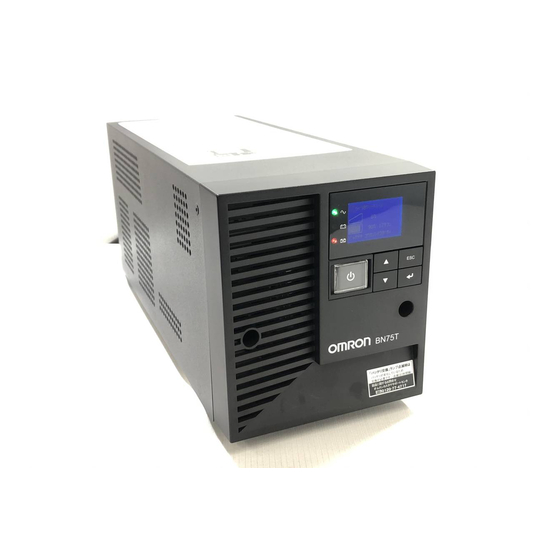
Uninterruptible Power Supply BN50T/BN75T/BN100T/ BN150T/BN220T/BN300T Instruction Manual 使用说明书 BN50T/BN75T BN100T/BN150T BN220T/BN300T This manual provides important safety-related information. Thoroughly read and understand this manual before installing and using the product. Keep this manual in a convenient location so that you can refer to it whenever necessary.
Page 3
10ms, and sine wave output is continued. l Output capacity is 500VA/450W for BN50T, 750VA/680W for BN75T, 1kVA/900W for BN100T, 1.5kVA/1350W for BN150T, 2.2kVA/1980W for BN220T, 3kVA/2700W for BN300T.
This symbol indicates earth ground. This symbol indicates turning on/off UPS. 3. INTERNAL BATTERY Internal battery voltage is 24VDC for BN50T/BN75T, 48VDC for BN100T/BN150T, and 96VDC for BN220T/BN300T. 4. TEMPERATURE RATING The maximum ambient temperature of the UPS is 40°C.
We recommend charging the UPS before using it. Operate 3. Check and start operation Perform maintenance and inspection The battery must Perform maintenance be replaced and inspection 4. Maintenance and Inspection Replace the battery 4.2 Replacing the battery BN50T/BN75T/BN100T/BN150T/BN220T/BN300T...
3-1-2 The meaning of each LED ..............3-1 3-1-3 Switch ....................3-2 3-1-4 Beep sound ..................3-3 3-1-5 LCD status screen ................3-4 3-1-6 Status screen example ............... 3-5 3-1-7 Icons, LEDs, and beeps..............3-5 3-1-8 Lower message ................... 3-8 Checking the operation ................ 3-9 BN50T/BN75T/BN100T/BN150T/BN220T/BN300T...
6-2-6 Items that can be set using the contact signal card ......6-5 6-2-7 Insert method of contact signal card ........... 6-5 Remote ON/OFF connector ..............6-6 6-3-1 Type of Input signal ................6-6 6-3-2 Remote ON/OFF connector ..............6-6 BN50T/BN75T/BN100T/BN150T/BN220T/BN300T...
Page 8
8 Troubleshooting ..................8-1 9 Note of Chinese ..................9-1 10 References ..................10-1 10-1 Specifications ..................10-1 10-2 Dimensions ..................10-2 10-3 Battery life .................... 10-4 10-4 Input voltage sensitivity settings ............10-5 10-5 China RoHS Information ..............10-6 保修单/保修协议条款 BN50T/BN75T/BN100T/BN150T/BN220T/BN300T...
Dropping or toppling the unit may cause injury. ● If you drop the unit, stop using it and have it inspected and repaired. l The approximate weight of the unit is 11 kg (BN50T/BN75T), 20 kg ● For repair, contact the shop of purchase.
Page 10
If you install the unit in an orientation other than specified, the unit cannot be protected Do not use the unit where the maximum temperature exceeds 40°C. from a battery fluid leakage. ● The battery deteriorates rapidly. ● Doing so may cause a failure or malfunction of the unit BN50T/BN75T/BN100T/BN150T/BN220T/BN300T...
Page 11
When the unit’s power switch is turned ON and an error occurs with the connected (for BN50T, BN75T, BN100T, BN159T) device, bypass operation is performed and commercial power supply is supplied as is An additional circuit breaker or fuse with breaking capacity 6kA shall be to the connected devices.
Page 12
Do not place objects heavier than 25 kg on the unit, and do not drop heavy objects onto the unit. l Doing so may cause distortion/damage to the case or a failure of the internal circuit, which may cause a fire. BN50T/BN75T/BN100T/BN150T/BN220T/BN300T...
Page 13
(for battery replacement) Perform replacement on a stable and flat place. Handle the battery carefully so that you do not drop it. Risk of injury due to falling, or burns due to fluid leakage (dilute sulfuric acid). BN50T/BN75T/BN100T/BN150T/BN220T/BN300T...
Page 14
Replacement battery pack for: Product model: BNB75T: One required (Replacement battery pack for BN50T/BN75T) BNB300T: One required (Replacement battery pack for BN100T/BN150T) BNB300T: Two required (Replacement battery pack for BN220T/BN300T) Do not replace the battery in a place where there is flammable gas.
Page 15
Do not use the unit for an inductive device such as a coil or motor. l With some types of devices, the effect of inrush current may cause this unit to stop operating properly. BN50T/BN75T/BN100T/BN150T/BN220T/BN300T...
Page 16
Turn OFF the unit’s power switch when storing it. Do not install or store the unit in a place exposed to direct sunlight. l The rise of temperature may cause the built-in battery to deteriorate rapidly and become unusable. BN50T/BN75T/BN100T/BN150T/BN220T/BN300T...
1-1 Unpacking the product Caution (for installation and connection) The approximate weight of the unit is 11 kg (BN50T/BN75T), 20 kg (BN100T/BN150T), 36 kg (BN220T), or 37 kg (BN300T). Note the weight when unpacking and transporting the unit. l Dropping may cause injury.
Page 18
1 Preparation Checking the contents UPS monitoring software related items BN50T, BN75T, BN100T, BN150T, BN220T, BN300T Quick Install Guide CD-ROM "PowerAct Pro" UPS monitoring software, “Simple Shutdown Software", and UPS service driver are included. Connection cable (RS232C, USB) One each cable length: 2.2m each...
This section describes the name of each part of the UPS. For information on the function of each part, refer to “2. Installation and connection” and “3. Check and start operation” that provides the details. Front view <BN50T/BN75T> <BN100T/BN150T> <BN220T/BN300T> (Operation panel)
Page 20
1 Preparation Name of each part Side view <BN50T/BN75T> "AC Input" plug Air vent AC input cable *The other side (right side as seen from the front) has a similar air vent. "AC Input" plug Air vent <BN100T/BN150T> AC input cable Air vent <BN220T/BN300T>...
1 Preparation Name of each part Rear view <BN50T/BN75T> G. Option slot A. AC Input cable D. RS-232C port B. AC Input overcurrent protection switch E. USB port H. Power supply output receptacle C. Grounding terminal (M4 screw) F. Remote ON/OFF port Air vent <BN100T/BN150T>...
Page 22
H. Power supply output receptacle A Left side: ON, right side: OFF I. Power supply output receptacle B C. Grounding terminal (M4 screw) J. Power supply output receptacle C D. RS-232C port K. Cooling fan E. USB port F. Remote ON/OFF port BN50T/BN75T/BN100T/BN150T/BN220T/BN300T...
1 Preparation Diagram of the Input/output circuit block 1-4 Diagram of the Input/output circuit block Power supply output receptacles BN50T/BN75T: without output receptacle control Input overcurrent protection AVR transforme Noise filter AC100V input BN100T/BN150T/BN220T/ BN300T: without output receptacle control Charger...
The product serial number label is also included. Allow sufficient space at the back for the AC input cables of the UPS unit and con- nected devices. Correct Positions Be careful not to get your fingers caught when arranging the unit. BN50T/BN75T/BN100T/BN150T/BN220T/BN300T...
Page 26
2 Installation and connection Installation Incorrect Positions BN50T/BN75T/BN100T/BN150T/BN220T/BN300T...
Power supply output group C . Disconnect the AC Input Plugs of all devices you want to back up such as your PC and modems from a wall outlet (commercial power source). Computer peripheral devices Wall outlet (commercial power source) BN50T/BN75T/BN100T/BN150T/BN220T/BN300T...
Page 28
. Connect devices you want to back up to the Power Supply Output Receptacles of the UPS. If you need more output receptacles than those of the UPS, purchase a plug strip and use it for extra output receptacles. BN50T/BN75T Computer peripheral devices External HDD...
Connecting to a wall outlet (commercial power source) of a different rated voltage may result in fire. The unit may fail. The BN50T/BN75T/BN100T AC input plug cannot be changed. The AC input plug for the BN150T/BN220T/BN300T can be changed according to the operating environment.
Make sure that the connecting work is performed by a qualified electrical engineer (with Type II certification or higher). 2-3-1 Connecting the AC input plug BN50T/75T connection procedure Provide a wall outlet (commercial power source) suitable for the shape of the 15A plug (NEMA 5-15R).
Page 31
When the AC Input Overcurrent Protection function works, the AC Input overcurrent protection switch automatically turns to OFF. In that event, disconnect all connected devices, switch the AC input overcurrent protection switch ON, and then switch the power switch on the unit back ON. BN50T/BN75T/BN100T/BN150T/BN220T/BN300T...
Page 32
Replacing the plug . Remove the 30A plug. . Connect the provided NEMA 5-15P plug as shown below. Note: Fasten with screws as shown, taking care that the wire colors are correct. N White L: Black FG: Green BN50T/BN75T/BN100T/BN150T/BN220T/BN300T...
. Remove screws at terminals (L, N, G (PE)) connecting the cable to the terminals and remove the old AC input cable. . Run the newly connected cable through the included AC input terminal block cover. BN50T/BN75T/BN100T/BN150T/BN220T/BN300T...
Page 34
1.355Nm (12 lb-in) or more. the screw . Fasten the AC input terminal block cover to the console with screws (2 screws). BN220T Tighten the screw Use Copper Conductor Onl y. Refer to the instruction manual for the tightening torque. BN50T/BN75T/BN100T/BN150T/BN220T/BN300T 2-10...
Page 35
When the AC Input Overcurrent Protection function works, the AC Input overcurrent protection switch automatically turns to OFF. In that event, disconnect all connected devices, switch the AC input overcurrent protection switch ON, and then switch the power switch on the unit back ON. BN50T/BN75T/BN100T/BN150T/BN220T/BN300T 2-11...
Page 36
2 Installation and connection BN50T/BN75T/BN100T/BN150T/BN220T/BN300T 2-12...
Backup is operating. This Backup is not operating. status is called “Battery Mode”. “Battery Battery replacement is neces- Battery replacement is not replacement” sary due to the battery deterio- necessary. ration, the end of battery life, or the end of UPS life. BN50T/BN75T/BN100T/BN150T/BN220T/BN300T...
Move cursor up or increase a value “Down” switch Move cursor down or decrease a value “ESC” switch Return to menu or cancel Stop the beeper by pressing for 0.5 seconds or longer “Enter” switch Select the menu item or set the value BN50T/BN75T/BN100T/BN150T/BN220T/BN300T...
“OFF at Anytime”, with “Setting” - “Local Setting” - “Audible Alarm” in the menu on the LCD. Stopping the beep sound When the beep is sounding, you can stop it by pressing and holding the “ESC” switch for 0.5 seconds or longer. BN50T/BN75T/BN100T/BN150T/BN220T/BN300T...
The backup time displays the time while the UPS can continue power output using power supplied from the battery in the unit of a minute. Lower text The lower text displays the message that urges the user to act. BN50T/BN75T/BN100T/BN150T/BN220T/BN300T...
Lit. Not lit. Not lit. None ECO mode mode ECO operation Testing Charg- Upper Icon Beep Output Description Solution status message OFF or Test Self-diagnostic test in Lit. Lit. Not lit. None dis- Test mode mode progress charging BN50T/BN75T/BN100T/BN150T/BN220T/BN300T...
Page 42
AC I/P AC input voltage described in the speci- abnormal-VL abnormal-VL fications Note: You can check AC I/P AC input frequency abnormal-FH abnormal-FH the input voltage with "Measurements" - AC I/P AC input frequency "Input/Output Meter". abnormal-FL abnormal-FL BN50T/BN75T/BN100T/BN150T/BN220T/BN300T...
Page 43
If 105% of rated capacity is exceeded under backup operations, the output stops in 30 seconds. If 125% is exceeded, the output immediately stops. Note 2: Not dependent on the state Note 3: For details, see "■ The contents of the UPS fault". BN50T/BN75T/BN100T/BN150T/BN220T/BN300T...
If 105% of rated capacity is exceeded under backup operations, the output stops in 30 seconds. If 125% is exceeded, the output immediately stops. 3-1-8 Lower message The message is displayed on the lower text of LCD according to the state of UPS. The message can be reference of your operation. BN50T/BN75T/BN100T/BN150T/BN220T/BN300T...
→ The operation is abnormal. One of the cases described one shown above: in “3-1-7 Icons, LEDs, and beeps.” and “3-3 Start and stop procedures and basic operation” must apply. Take necessary measures and then proceed to procedure 5 BN50T/BN75T/BN100T/BN150T/BN220T/BN300T...
Page 46
. Reconnect the AC input plug to the commercial power source. The icon returns to its normal state and the beeping sound stops. (The status is as shown below.) Icon Description Power switch “ON” Operating normally Checking the operation is now complete. Installation and connection is now complete. BN50T/BN75T/BN100T/BN150T/BN220T/BN300T 3-10...
Choose whichever operation method is more convenient. We recommend turning OFF the power switch when you do not use connected devices for a long time. The battery can be charged once the AC input plug is connected to a commercial power source. BN50T/BN75T/BN100T/BN150T/BN220T/BN300T 3-11...
Page 48
If you do not want to restart the connected devices, disable the “Settings” - “Boot Settings” - “Auto Reboot” setting in the menu on the unit's LCD, or turn OFF the power switch of the connected devices. BN50T/BN75T/BN100T/BN150T/BN220T/BN300T 3-12...
3-4 Operation from the LCD menu 3-4-1 The menu screen for the UPS settings Menu title Previous/next page mark Menu list Selected item is highlighted. Pop-up window Displayed for additional information or when confirmation is required. BN50T/BN75T/BN100T/BN150T/BN220T/BN300T 3-13...
Page 50
3 Check and start operation Operation from the LCD menu Basic operations on the menu screen Switch Description Move cursor up/down or increase/decrease values Select the menu item or set the value Return to menu or cancel BN50T/BN75T/BN100T/BN150T/BN220T/BN300T 3-14...
Are you sure? Yes or No Setting Local Language Set the language to be dis- Language: Standard Setting played on the LCD. Japanese (Default), English LCD Setting Change the contrast of the LCD Setting: LCD. Contrast bar BN50T/BN75T/BN100T/BN150T/BN220T/BN300T 3-15...
Page 52
Set this when replacing the Input Plug: input plug. 15A, 20A, 30A, Hard wire/50A (dependent on the UPS model) (Default: BN50T / BN75T / BN100T / BN150T: 15A, BN220T / BN300T:30A ECO Mode * Set whether to enable ECO ECO mode: Advanced Mode.
Page 53
Year/Month/Day/Hour/ Min, Message Reset All Log Data Clear each log. Reset All Log Are you sure? Yes or No Note 1: Refer to “9-4 Checking and Setting the Output Voltage Range”. Note 2: Refer to “9-3 Battery life”. BN50T/BN75T/BN100T/BN150T/BN220T/BN300T 3-17...
Page 54
3 Check and start operation BN50T/BN75T/BN100T/BN150T/BN220T/BN300T 3-18...
Test” in the LCD menu. “Start up/Every 4w (Default)”, “Start up”, “Every 4w”, or “Disable” The self-diagnosis test can be performed also from attached UPS monitoring software. For more details, refer to the online help of UPS monitoring software. BN50T/BN75T/BN100T/BN150T/BN220T/BN300T...
The backup time becomes shorter than the graph (table) below when temperature is lower. The smaller the capacity of connected devices becomes, the longer the backup time becomes. Backup time (25°C, Initial Value) BN50T BN100T BN75T BN220T BN150T BN300T...
Page 57
4 Maintenance and Inspection Checking the battery Backup time table Time unit: (Minutes) BN50T Connection capacity (W) Backup time 15.5 10.5 (Minutes) BN75T Connection capacity (W) Backup time 15.5 10.5 (Minutes) BN100T Connection capacity (W) Backup time (Minutes) BN150T Connection...
For the first 3 years after start- When 3 years or more have ing use passed after starting use 25°C For the first 4 years after start- When 4 years or more have ing use passed after starting use BN50T/BN75T/BN100T/BN150T/BN220T/BN300T...
For cautions when replacing the battery of the UPS, refer to “Caution for battery replacement)” shown in the "Safety precautions" of the beginning of this manual. BN50T/BN75T . Use a screwdriver to loosen (turn counter-clockwise) the 2 screws at the top of the front panel of the unit, until they turn freely.
Page 60
Hold the battery securely with both hands so as not to drop it. Battery connector Battery pack Pullout label (Pull this to remove.) BN50T/BN75T/BN100T/BN150T/BN220T/BN300T...
Page 61
. Insert a new battery into the UPS as far as it will go. 1) Replacement battery pack BN50T/BN75T: Model BNB75T Attach the plate cover in order of 2) to 3). Use a screwdriver to securely tighten (clockwise) the 2 screws you removed. 4) Do not pinch the cable with the plate cover.
Page 62
Write the battery replacement date on the included battery replacement date label, and attach the label to the unit. Or, enter the battery replacement date from the “Setting” - “Battery Settings” - “Battery Installation” screen in the menu on the LCD. BN50T/BN75T/BN100T/BN150T/BN220T/BN300T...
Page 63
(2)-1), move to the center of the hole (2)-2), and pull the connector to the back to unlock (2)-3). Hold the battery connector, and pull the connectors apart. 3) Back of the plate cover 2)-1 2)-2 2)-3 Move connector Battery to hole’s connector center Connector Connector unlock locked Pullout label (Pull this to remove.) BN50T/BN75T/BN100T/BN150T/BN220T/BN300T...
Page 64
Hold the battery securely with both hands so as not to drop it. Battery connector Pullout label (Pull this to remove.) Battery pack BN50T/BN75T/BN100T/BN150T/BN220T/BN300T 4-10...
Page 65
Note: You may hear a “pop” sound when you connect the battery if it is replaced after the unit's operation is stopped, but this sound is not abnormal. Back of the plate cover 2)-1 2)-2 2)-3 Connector move through Battery connector the hole Connector locked Connector’s hook align the hole BN50T/BN75T/BN100T/BN150T/BN220T/BN300T 4-11...
Page 66
Write the battery replacement date on the included battery replacement date label, and attach the label to the unit. Or, enter the battery replacement date from the “Setting” - “Battery Settings” - “Battery Installation” screen in the menu on the LCD. BN50T/BN75T/BN100T/BN150T/BN220T/BN300T 4-12...
Page 67
Hold the battery connector, and pull the connectors apart. 2) Do this for both battery connectors. Back of the plate cover 1)-1 1)-2 1)-3 Move Battery connector connector to hole’s center Connector Connector locked unlock Disconnect by holding here. BN50T/BN75T/BN100T/BN150T/BN220T/BN300T 4-13...
Page 68
Hold the battery securely with both hands so as not to drop it. Battery connector Battery pack Pullout label (Pull this to remove.) BN50T/BN75T/BN100T/BN150T/BN220T/BN300T 4-14...
Page 69
Hold the battery securely with both hands so as not to drop it. Battery connector Battery pack Pullout label (Pull this to remove.) BN50T/BN75T/BN100T/BN150T/BN220T/BN300T 4-15...
Page 70
Note: You may hear a “pop” sound when you connect the battery if it is replaced after the unit’s operation is stopped, but this sound is not abnormal. Battery connector 2)-1 2)-2 2)-3 Connector move through the hole Connector Connector’s hook locked align the hole BN50T/BN75T/BN100T/BN150T/BN220T/BN300T 4-16...
Stop all the connected devices and the UPS and disconnect the AC input plug from a wall outlet (commercial power source). Then, remove dust with a dry cloth and make the connection again. (For information on the connection procedure:) See also "2-2 Connecting the equipment" BN50T/BN75T/BN100T/BN150T/BN220T/BN300T 4-17...
Page 72
4 Maintenance and Inspection BN50T/BN75T/BN100T/BN150T/BN220T/BN300T 4-18...
Telnet connection Supported SYSLOG support Supported Supported Note 1: The UPS automatically stops only when the battery is depleted. (Battery Mode con- tinues until the battery is depleted.) Note 2: This function is available only for Windows, not for Linux. BN50T/BN75T/BN100T/BN150T/BN220T/BN300T...
Page 74
SNMP manage- UPS management information can be sent to the SNMP manager. ment Telnet connection Settings such as shutdown parameters can be made via the Telnet connection. SYSLOG support UPS management information can be recorded in SYSLOG. BN50T/BN75T/BN100T/BN150T/BN220T/BN300T...
For the latest support, please visit our site. Support for OS http://www.omron.co.jp/ese/ups/product/soft/os_ups_sentaku.pdf You can download the latest software at: http://www.omron.co.jp/ese/ups/support/download/download.html Caution (for installation and connection) When this product is used in compliance with CE marking, please use under 3m con- nection cable. BN50T/BN75T/BN100T/BN150T/BN220T/BN300T...
For more information, refer to the manual in the CD-ROM. 5-2-3 How to connect . Connect the UPS to a computer. Cable: Included connection cable (RS-232C or USB) Note: The RS-232C and USB cannot be used at the same time. <RS-232C> BN50T/BN75T BN100T/BN150T Connect to Connect to RS-232C RS-232C...
Page 77
5 To perform shutdown processing of the devices when a power failure occurs When using the included UPS monitoring software <USB> BN100T/BN150T BN50T/BN75T Connect to Connect to USB terminal USB terminal Connect to Connect to USB Port on USB Port on...
Page 78
UPS automatically restarts and supplies power. If you do not want connected devices to operate, turn off the switch of the connected devices or disable the auto reboot after power restoration setting (LCD menu - [Setting] - [Boot Setting] - [Auto Reboot]). BN50T/BN75T/BN100T/BN150T/BN220T/BN300T...
For the contact signal card loading procedure, refer to “6-2-7 Insert method of contact signal card”. . Perform UPS service setup. You need to make Windows settings in order to perform auto shutdown. There is no need to install software. BN50T/BN75T/BN100T/BN150T/BN220T/BN300T...
Page 80
5 To perform shutdown processing of the devices when a power failure occurs BN50T/BN75T/BN100T/BN150T/BN220T/BN300T...
Additional Information A relay output type contact signal card (model number: SC08) is available for sep- arate purchase. It can be loaded into the option slot on the back of the UPS. Visit our website for more details. (URL: http://www.omron.co.jp/ese/) BN50T/BN75T/BN100T/BN150T/BN220T/BN300T...
Goes ON when an internal failure of the UPS occurs or when the battery life counter expires. Battery Replacement Signal output Goes ON when the test determines that battery replace- (WB) ment is necessary due to deterioration or when the bat- tery life counter goes off-scale. BN50T/BN75T/BN100T/BN150T/BN220T/BN300T...
-Applicable voltage: 35 VDC or less -Maximum current: 20 mA UPS Stop Signal input (BS) Input voltage -HIGH(ON) 5 to 12 VDC -LOW(OFF) 0.7 VDC or less Remote ON/OFF Signal Voltage between terminals: 10 VDC Current when closed: max.10 mA BN50T/BN75T/BN100T/BN150T/BN220T/BN300T...
C1,C2 : 0 pF to several UPS side thousand pF Connecting cable Inside of External (Consider the capacity according to the (twisted or shielded) Circuit operating environment.) Remote ON/OFF circuit Example of remote ON/OFF remote ON/OFF( + ) remote ON/OFF( - ) UPS side BN50T/BN75T/BN100T/BN150T/BN220T/BN300T...
Note 2: Factory settings: SC07 side for JP2 to JP9, SC05/06/07 side for JP10 6-2-7 Insert method of contact signal card . Remove the screws above and below the option slot (2 screws) on the back of the unit, and remove the cover. <BN50T/75T> <BN100T/150T> <BN220T/300T> BN50T/BN75T/BN100T/BN150T/BN220T/BN300T...
6 Using the contact signal functions Remote ON/OFF connector . Carefully insert the contact signal card whose settings have been changed, and se- curely tighten the 2 screws. <BN50T/75T> <BN100T/150T> <BN220T/300T> Note When connecting a device such as a relay that generates counter electromotive force to the signal output circuit, connect diodes that prevent counter electromotive force to both ends of the relay.
6 Using the contact signal functions Remote ON/OFF connector 6-3-3 Signal input circuit Remote ON/OFF signal 10KΩ Remote ON/OFF(+) Remote ON/OFF(-) 6-3-4 Remote ON/OFF circuit Remote ON/OFF signal Example of remote ON/OFF remote ON/OFF( + ) remote ON/OFF( - ) UPS side BN50T/BN75T/BN100T/BN150T/BN220T/BN300T...
Page 88
6 Using the contact signal functions BN50T/BN75T/BN100T/BN150T/BN220T/BN300T...
An SNMP/Web card can be loaded into the option slot on the back of the unit. SNMP/Web card (model number: SC20G, SC20G2), sold separately . Remove the 2 screws, and remove the cover. <BN50T/75T> <BN100T/150T> <BN220T/300T> . Carefully insert the SNMP/Web card, and securely tighten the 2 screws.
Number of controllable computers 32 max. (including slave UPS when coordinated shutdown is enabled) Support MIB UPSMIB (RFC1628) OMRON MIB Operating temperature/humidity 0 to 40°C/25 to 85% * Note that the range of the operating tempera- ture/humidity differs from that of BN-T.
(Note 1). If the indication changes, the connected device might have caused the failure. If you have any questions, contact the shop of purchase. Note: Output voltage can be viewed by selecting [Measurement] menu - [Input/ Output]. BN50T/BN75T/BN100T/BN150T/BN220T/BN300T...
Page 92
· Power switch short-circuit with above operation, there is a does the connected problem with the unit. not work *:For BN50T/75T/100T/150T, devices. press the black button. For BN220T/300T, press the AC Input overcurrent protec- tion switch. None Standby by...
Page 93
If 105% of rated capacity is exceeded under backup operations, the output stops in 30 seconds. If 125% is exceeded, the output immediately stops. Note 2: Maximum 2-types message may be displayed by turns on the LCD. BN50T/BN75T/BN100T/BN150T/BN220T/BN300T...
10 References 10-1 Specifications 10 References 10-1 Specifications Model BN50T BN75T BN100T BN150T BN220T BN300T Operation method Line-interactive method Method Cooling method Natural air cooling Forced air cooling Rated input voltage 100 V AC Standard sensitivity setting 89±2 to 118±2 V AC...
(and the battery level lowers) to approximately 80% over half a year, and to approximately 50% over a year. Higher the storage temperature is, faster the battery will self-discharge. Storage temperature Auxiliary charging interval 40°C or less 2 months 30°C or less 4 months 25°C or less 6 months BN50T/BN75T/BN100T/BN150T/BN220T/BN300T 10-4...
When you want to narrow the output voltage range Standard 89 to 118 VAC 90 to 114 VAC When using in a regular environment 84 to 118 VAC 84 to 114 VAC When you want to reduce the frequency of operation in Battery Mode. BN50T/BN75T/BN100T/BN150T/BN220T/BN300T 10-5...
The content of such hazardous substance in all homogeneous materials of such component is below the limit required by GB/T 26572. × : 表示该有害物质至少在该部件的某一均质材料中的含量超出 GB/T 26572 规定的限量要求。 The content of such hazardous substance in a certain homogeneous materials of such component is beyond the limit required by GB/T 26572. BN50T/BN75T/BN100T/BN150T/BN220T/BN300T 10-6...
Page 110
No part or whole of this manual may be reproduced without permission. The contents of this manual are subject to change without notice. OMRON Corporation K1L-D-13062F...
Need help?
Do you have a question about the BN50T and is the answer not in the manual?
Questions and answers