Table of Contents
Advertisement
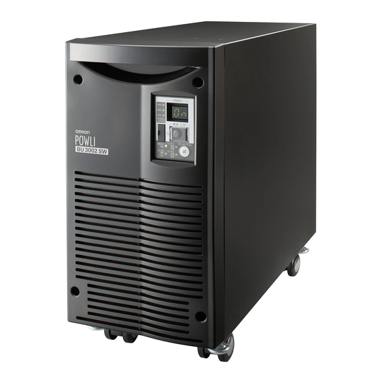
Uninterruptible Power Supply (UPS/200 to 240V specifi cations)
Instruction Manual
• This manual provides important safety-related information. Thoroughly read and understand
this manual before installing and using the product.
• Keep this manual in a convenient location so that you can refer to it whenever necessary.
BU1002SW/BU3002SW
バッテリ
ブザー停止/テスト
電源出力
増設
-
バイパス
バッテリ
運転
交換
バッテリ
ブザー停止/テスト
電源出力
増設
-
バイパス
バッテリ
運転
交換
BU 10 02S W
Advertisement
Table of Contents

Related Manuals for Omron BU1002SW


Summary of Contents for Omron BU1002SW
- Page 1 Uninterruptible Power Supply (UPS/200 to 240V specifi cations) BU1002SW/BU3002SW Instruction Manual バッテリ ブザー停止/テスト 電源出力 増設 バイパス バッテリ 運転 交換 バッテリ ブザー停止/テスト 電源出力 増設 バイパス バッテリ 運転 交換 BU 10 02S W • This manual provides important safety-related information. Thoroughly read and understand this manual before installing and using the product.
- Page 2 This is especially suitable for use where power supply conditions are poor (for example, when there are large variations in voltage). ● BU1002SW output capacity is 1000VA/700W, and BU3002SW output capacity is 3000VA/2100W. Notes on the use of the Backup Power Supply ●...
-
Page 3: Important Safety Instruction
This symbol indicates turning on UPS. This symbol indicates turning off UPS. 3. INTERNAL BATTERY Internal battery voltage is 36V DC for BU1002SW and 72V DC for BU3002SW. 4. TEMPERATURE RATING The maximum ambient temperature of the UPS is 40 °C . - Page 4 Ce symbole indique la mise sous tension de l’ASC. Ce symbole indique la mise hors tension de l’ASC. 3. BATTERIE INTERNE La tension de la batterie interne est de 36V DC pour BU1002SW et de 72V DC pour BU3002SW. 4. TEMPÉRATURE NOMINALE La température ambiante maximale de l’ASC est de 40ºC.
-
Page 5: Preparation For Operation
1002 3002 SW / BU Procedure from installation to operation Read “Safety precautions” Start Page iii Remove the product from the package and check the contents Page 1 Installation/connection Perform installation and connection Page 6 Are you Read “Using the UPS using UPS monitoring monitoring software and software or contact... -
Page 6: Table Of Contents
Table of Contents ■ Table of Contents ■ Introduction IMPORTANT SAFETY INSTRUCTION Safety precautions ............................. iii 1. Preparation ..........................1 1-1 Unpacking the product........................... 1 1-2 Checking the contents ........................... 1 1-3 Name of each part ............................2 1-4 Explanation of symbols used on unit ......................5 2. -
Page 7: Safety Precautions
Carry the unit considering its weight and balance, and place it on a stable and robust base. ● Dropping or toppling the unit may cause injury. ● Approximate weight of the unit: 15.5 kg (BU1002SW) 35 kg (BU3002SW) ● If you drop the unit, stop using it and have it inspected and repaired. - Page 8 fl ow through. ● Overcurrent may damage the UPS. Connect the BU1002SW to a wall outlet (commercial power) with a capacity of 7.4A or more, and connect the BU3002SW to a wall outlet (commercial power) with a capacity of 16A or more.
- Page 9 UPS and the connected consumer does not exceed 3.5mA. Do not block the air vents on the unit. The BU1002SW has air vents on the front, side and back, while the BU3002SW has air vents on the front and back.
- Page 10 Safety precautions Caution (for use) Never touch the metal part of the input plug if it is disconnected while the unit is operating. ● Doing so may result in electric shock. ● The leak current of this product itself is less than the value of the safety standard (leak current: 1 mA).
- Page 11 Use a specifi ed battery for replacement. ● Not doing so may cause a fi re. ● Product model: BP100XS (Replacement battery pack for BU1002SW) BP150XS: Two required (Replacement battery pack for BU3002SW) Do not replace the battery in a place where there is fl ammable gas.
- Page 12 Safety precautions Caution (for battery replacement) Do not put the battery into fi re and do not break it. ● The battery may explode or leak dilute sulfuric acid. Do not use a new battery and an old battery at the same time. ●...
- Page 13 1002 3002 SW / BU Notes When moving the unit from a cold place to a warm place, leave it for several hours before using it. ● If the unit is promptly turned ON after being moved to a warmer place, condensation may form inside the unit and cause it to fail.
- Page 14 Safety precautions Notes Check the operation beforehand if the unit is used in any mode other than “Output 200V mode”. ● In Battery Mode, the maximum voltage (peak voltage) of output (rectangular wave) may be lower than the maximum voltage in Commercial Power Mode. For this reason, some connected devices may fail to operate normally.
- Page 15 ● Une chute ou un renversement de l’appareil peut causer des blessures. ● Poids approximatif de l’appareil : 15,5 kg (BU1002SW) 35 kg (BU3002SW) ● En cas de chute de l’appareil, cesser de l’utiliser et le faire inspecter et réparer.
- Page 16 AC de les parcourir. ● La surtension peut endommager l’ASC. Brancher le BU1002SW à une prise murale (alimentation secteur) d’une puissance de 7,4A ou plus, et brancher le BU3002SW à une prise murale (alimentation secteur) d’une puissance de 16A ou plus.
- Page 17 ● Lors de l’installation de l’équipement, s’assurer que la somme du courant de fuite de l’ASC et du récepteur raccordé ne dépasse pas 3,5 mA. Ne pas obstruer les bouches d’aération de l’appareil. Le BU1002SW est équipé de bouches d’aération à l’avant, sur le côté et à l’arrière, tandis que le BU3002SW est équipé...
- Page 18 Safety precautions Attention (pour l’installation et le raccordement) Lors de l’utilisation, s’assurer que le couvercle du bornier de sortie est bien fi xé. Ne pas allumer l’interrupteur d’alimentation lorsqu’il est détaché. ● Une tension est appliquée au bornier de sortie lorsque l’interrupteur d’alimentation est allumé, ce qui peut provoquer un choc électrique.
- Page 19 Utiliser une batterie spécifi ée lors du remplacement. ● Ne pas le faire peut provoquer un incendie. ● Modèle du produit : BP100XS (Batterie de rechange pour le BU1002SW) BP150XS : Deux requises (Batterie de rechange pour le BU3002SW) Ne pas changer la batterie en présence de gaz infl ammable.
- Page 20 Safety precautions Attention (pour le remplacement de la batterie) Ne pas démonter ou modifi er la batterie. ● Cela peut entraîner une fuite d’acide sulfurique dilué, ce qui peut causer la cécité et des brûlures. Ne pas faire tomber la batterie ni l’exposer à des chocs violents. ●...
- Page 21 1002 3002 SW / BU Remarques Lorsque l’appareil est déplacé d’un endroit froid à un endroit chaud, le laisser au repos pendant plusieurs heures avant de l’utiliser. ● Si l’appareil est rapidement mis en marche après avoir été déplacé à un endroit plus chaud, de la condensation peut se former à...
- Page 22 Safety precautions Remarques Ne pas effectuer d’essai de rigidité diélectrique. ● Le circuit d’entrée comporte un dispositif d’absorption de surtension intégré. Un essai de rigidité diélectrique peut le détruire. ● Lors de l’exécution d’un test de résistance d’isolation, utiliser la gamme 400V DC. Avant d’arrêter l’alimentation secteur de l’appareil, éteindre l’interrupteur d’alimentation de l’appareil.
-
Page 23: Preparation
BU3002SW. ● Because the unit is heavy, you may injure yourself or drop the unit, or it may fall over. The weight of the product is 15.5 kg (BU1002SW) , 35 kg (BU3002SW). Unpack/transport this product considering this weight. -
Page 24: Name Of Each Part
This section describes the name of each part of the UPS. For information on the function of each part, refer to "2. Installation and connection" on page 6 and "3. Operation" on page 32 that provides the details. Front view <BU1002SW> <BU3002SW> (Carrying handle) <Display panel>... - Page 25 1002 3002 SW / BU Side view <BU1002SW> Front side Rear side Air inlet <BU3002SW> Front side Rear side...
-
Page 26: Rear View
. Preparation Rear view <BU1002SW> A. USB connector B. RS-232C connector C. Contact signal card D. Contact signal connector E. Remote ON/OFF connector F. Additional battery connector G. Power supply output receptacle A (IEC60320 C13) H. Power supply output receptacle B (IEC60320 C13) Power supply output receptacle C (IEC60320 C13) J. -
Page 27: Explanation Of Symbols Used On Unit
1002 3002 SW / BU Explanation of symbols used on unit Symbol Description Start the UPS. Stop the UPS. Suspend a beep. UPS output power enabled, supplied by operating on line mode, battery mode. UPS operating on battery mode. Additional battery unit connected to the UPS. (For BU100XS only.) Error occurred with UPS. -
Page 28: Installation And Connection
fl ow through. ● Overcurrent may damage the UPS. Connect the BU1002SW to a wall outlet (commercial power) with a capacity of 7.4A or more, and connect the BU3002SW to a wall outlet (commercial power) with a capacity of 16A or more. - Page 29 1002 3002 SW / BU Caution (for installation and connection) Do not install the unit in other than specifi ed orientations. ● Dropping or toppling the unit may cause injury. ● If you install the unit in an orientation other than specifi ed, the unit cannot be protected from a battery fl...
- Page 30 . Installation and Connection Caution (for installation and connection) Do not block the air vents on the unit. The BU1002SW has air vents on the front, side and back, while the BU3002SW has air vents on the front and back.
- Page 31 1002 3002 SW / BU Notes Do not short the output lines of the unit to each other, and do not short the output lines to the ground. ● The unit may fail. Do not connect the AC input plug of the unit to its Power Supply Output Receptacle during the Battery Mode.
- Page 32 AC de les parcourir. ● La surtension peut endommager l’ASC. Brancher le BU1002SW à une prise murale (alimentation secteur) d’une puissance de 7,4A ou plus, et brancher le BU3002SW à une prise murale (alimentation secteur) d’une puissance de 16A ou plus.
- Page 33 1002 3002 SW / BU Attention (pour l’installation et le raccordement) Ne pas démonter, réparer ou modifi er l’appareil. ● Cela peut provoquer un choc électrique ou un incendie. Ne pas installer l’appareil dans une autre position que celles indiquées. ●...
- Page 34 ● Lors de l’installation de l’équipement, s’assurer que la somme du courant de fuite de l’ASC et du récepteur raccordé ne dépasse pas 3,5 mA. Ne pas obstruer les bouches d’aération de l’appareil. Le BU1002SW est équipé de bouches d’aération à l’avant, sur le côté et à l’arrière, tandis que le BU3002SW est équipé...
- Page 35 1002 3002 SW / BU Remarques Lorsque l’appareil est déplacé d’un endroit froid à un endroit chaud, le laisser au repos pendant plusieurs heures avant de l’utiliser. ● Si l’appareil est rapidement mis en marche après avoir été déplacé à un endroit plus chaud, de la condensation peut se former à...
- Page 36 . Installation and Connection Remarques Ne pas effectuer d’essai de rigidité diélectrique. ● Le circuit d’entrée comporte un dispositif d’absorption de surtension intégré. Un essai de rigidité diélectrique peut le détruire. ● Lors de l’exécution d’un test de résistance d’isolation, utiliser la gamme 400VDC. Avant d’arrêter l’alimentation secteur de l’appareil, éteindre l’interrupteur d’alimentation de l’appareil.
-
Page 37: Installation And Connection
Before installing this device, make a record of the serial number of this device. The serial number is required when contacting us about the device. The serial number is written in the label on the unit's top side. < BU1002SW > Correct Positions Be careful not to get your fingers caught when arranging the unit. - Page 38 . Installation and Connection < BU3002SW > Correct Positions Be careful not to get your fingers caught when arranging the unit. Caster at the bottom may be removed when sitting horizontally. バッテリ ブザー停止/テスト 電源出力 増設 バイパス バッテリ 運転 交換 (Display panel are facing upward) Incorrect Positions...
- Page 39 Le numéro de série est nécessaire pour nous contacter au sujet de l’appareil. Le numéro de série est inscrit sur l’étiquette sur la face supérieure de l’appareil. < BU1002SW > Positions correctes Faire attention à ne pas se coincer les doigts lors de l'installation de l'appareil.
- Page 40 . Installation and Connection < BU3002SW > Positions correctes Faire attention à ne pas se coincer les doigts lors de l'installation de l'appareil. Les supports inférieurs peuvent être retirés en position horizontale. バッテリ ブザー停止/テスト 電源出力 増設 バイパス バッテリ 運転 交換 Positions incorrectes...
- Page 41 1002 3002 SW / BU <Installing the BU3002SW vertically> ● Stabilize the casters Casters locked Casters unlocked ● How to stabilize the fi xed stand Use a monkey wrench or spanner to loosen the fi xed stand nuts. Unscrew the feet of the fi xed stand until they reach the fl...
-
Page 42: Connecting The Equipment
● Group control of power supply output This function can be used with the UPS monitoring software included with the UPS. The output receptacles of the BU1002SW are separated into 3 groups: A, B, and C. 1. Power supply output group A... - Page 43 The output start/stop time control funtion is available when using the included “PowerAct Pro” UPS monitoring software, “UPS Power Manager” or “SNMP/Web card”. • Output ON/OFF can be controlled with the included UPS monitoring software while the BU1002SW is operating. •...
- Page 44 • Procedure for connection to power supply output receptacle (IEC60320 C13) Connect it directly. Plug of connected device ● Procedure for connection to BU1002SW output terminal block Caution When in use, make sure the output terminal block cover is attached.
- Page 45 1002 3002 SW / BU (1) Remove the terminal block cover on the lower right side of the unit’s <BU1002SW> rear panel. (2) Connect the units that need to be backed up. Two types of connections can be made. 1) To turn ON/OFF at the same timing as that of output receptacle B:...
- Page 46 (alimentation secteur) avec une tension nominale d’entrée (200 à 240V AC). ● Le branchement à une prise murale (alimentation secteur) d’une tension d’entrée nominale différente peut entraîner un incendie. ● L’appareil peut tomber en panne. <BU1002SW> 200 to 240 VAC 3P receptacle Grounding terminal Connect the ground wire to the Grounding terminal.
- Page 47 1002 3002 SW / BU 2-3-2 Connecting a device to the power supply output (BU3002SW) (1) Connect devices that require backup to the unit's power supply output receptacle or output terminal block. Make sure that the total capacity of the devices connected to the output receptacle does not exceed the output rated capacity of the BU3002SW.
- Page 48 . Installation and Connection ● Procedure for connection to BU3002SW output terminal block Caution When in use, make sure the output terminal block cover is attached. Do not turn ON the power switch when it is detached. ● Voltage is applied to the output terminal block when the power switch is ON, which can result in electric shock.
- Page 49 1002 3002 SW / BU (4) Run the wires to be connected through the hole in the included terminal block cover (with cable clamp and cable guard tube). (See Figure 1.) Connect the ground wire to the G terminal. Use a Phillips screwdriver to remove the terminal block screws, and connect the wire attached to the round pressure terminal.
- Page 50 . Installation and Connection <BU3002SW> 200 to 240 VAC 3P receptacle Grounding terminal Connect the ground wire to the Grounding terminal. ● The UPS has been charged prior to shipment. However, the backup time becomes shorter when using it for the fi rst time due to spontaneous discharge. We recommend charging the UPS before using it.
-
Page 51: Checking The Operation
1002 3002 SW / BU Checking the operation After you fi nish connecting devices to the unit, make sure the backup function operates properly. Check that the Battery Mode is performed normally according to the following procedure. (This operation check simulates a power failure by disconnecting the AC input plug from a wall outlet.) (1) Turn ON the unit's power switch. - Page 52 . Installation and Connection (5) In Battery Mode, check the unit's LED display and beep sound. Does the status indicator appear as one of those shown below? indicates blinking) Status indicator Beep Output Charging Description Intermittent Backup is operating due to power failure or AC input error. 4-second Discharging Output will stop if Battery Mode continues.
-
Page 53: Charging The Battery
1002 3002 SW / BU Charging the battery When you connect the AC input plug of this unit to a wall outlet (commercial power), the battery charging automatically starts regardless of whether the power switch is ON or OFF, and it is fully charged within 8 hours. -
Page 54: Operation
. Operation Operation Precautions and notes for operation Caution (for use) Never touch the metal part of the input plug if it is disconnected while the unit is operating. ● Doing so may result in electric shock. ● The leak current of this product itself is less than the value of the safety standard (leak current: 1 mA). - Page 55 1002 3002 SW / BU Notes Before stopping the commercial power to the unit, turn OFF the power switch of the unit. ● The unit enters Battery Mode when commercial power is stopped. If you frequently use the unit in Battery Mode, the battery life may be signifi...
-
Page 56: Start And Stop Procedures And Basic Operation
. Operation Start and stop procedures and basic operation ● When the power switch is OFF and the AC input plug is connected to a commercial power supply: • The details of the most recent error are displayed. (item 4 on page 37) •... - Page 57 1002 3002 SW / BU ● Operation after a power failure • If a power failure or abnormal input power supply occurs, the UPS automatically switches to Battery Mode, continuing power output from the Power Supply Output Receptacles supplied from the battery. •...
- Page 58 In Commercial Power Mode (normal operation), the power consumption of devices connected to the capacity/battery level meter is displayed as a percentage. BU1002SW: Displayed in 3 levels, with 1000VA/700W as 100%. BU3002SW: Displayed in 3 levels, with 3000VA/2100W as 100%.
-
Page 59: Interpreting Beeps And Displays
1002 3002 SW / BU Interpreting beeps and displays indicates the display is OFF) ○ indicates the display is ON) ● 1. Displays and beeps in normal operation indicates blinking) Bypass Power supply Battery Status operation output Beep Charging Description Solution replacement indicator... - Page 60 . Operation indicates the display is OFF) ○ indicates the display is ON) ● 4. Displays and beeps when there is an equipment failure (continued) indicates blinking) Bypass Power supply Battery Status operation Beep Charging Description Solution output replacement indicator lamp lamp lamp...
-
Page 61: Ups Functions
UPS functions Suspending a beep When the beep is sounding, you can suspend it by pressing and holding the beep stop/test switch for 0.5 seconds or longer. バッテリ ブザー停止/テスト 電源出力 増設 バイパス バッテリ 交換 運転 Self-diagnosis test This test performs a failure diagnosis on the unit and performs a simple test to check for battery deteriora- tion. -
Page 62: Description Of The Auto Battery Test Function
. UPS functions Description of the auto battery test function This test performs a failure diagnosis on the unit and performs a test to check for battery deterioration. (This test is more accurate than the self-diagnostic test.) This test is performed automatically. (You do not have to perform any special operations.) The test is performed at intervals of 4 weeks after the AC Input Plug is connected to a wall outlet (commercial power). - Page 63 1002 3002 SW / BU Setting switch function list Function to set OFF side ON side Setting for beeper sound in the Beeper does Beeper sounds event of power failure, etc. not sound Do not perform Auto startup setting after Perform auto startup auto startup recovery from power failure...
- Page 64 . UPS functions ● Setting for whether or not to perform battery test (setting switch 3 ) … Factory setting: OFF OFF: The battery test is automatically executed once every 4 weeks. Does not perform the auto battery test. Use this setting to disable Battery Mode for for the regularly performed auto battery test. ●...
- Page 65 1002 3002 SW / BU (1) When BS signal is used to stop the UPS after a power failure occurs (1)-1. AC input BS signal Power output (Setting switch 4 OFF: Mode A) Power output (Setting switch 4 ON: Mode B) (2) When BS signal is used to shut down the UPS when AC input is ON 1 sec AC input...
- Page 66 . UPS functions ● BS signal valid range setting (setting switch 7 ) … Factory setting: OFF OFF: The BS signal is always valid (receivable). The unit’s “power output” can be stopped by inputting a “ON” backup power supply stop signal (BS) that continues for 10 seconds or more.
- Page 67 1002 3002 SW / BU 2. UPS operation mode settings 2-1 Settable items and explanations There are 4 items to select. 1) Cold start ON/OFF setting 2) Output voltage setting 3) Power output stop delay time setting 4) Signal input/output test The settings available for this operation are shown below.
- Page 68 . UPS functions 4) Signal input/output test (BL/TR/BU/WB/BS/remote) ● Four types of output signal can be forcibly turned ON. ● The ON/OFF state of two types of input signal can be checked with the status indicator and the beeper. Signal input/output test end Signal input test While the signal is being Signal input/output test start...
- Page 69 1002 3002 SW / BU 2-2 Settings The UPS operation mode can be set if the power switch is turned ON while the beeper stop switch is pressed. Note: While in setting mode, output from the power supply output is OFF even if the power switch is バッテリ...
- Page 70 . UPS functions Turn ON the power switch while the beep stop/test switch is pressed. Normal status There is AC input Turn OFF the power switch. Power switch “OFF” (Status No. 2) Press and hold the beep stop/test switch (for more than 3 seconds). Press the beep stop/test switch (for less than 3 seconds).
-
Page 71: Measuring The Backup Time
1002 3002 SW / BU Measuring the backup time How to measure backup time Caution Never touch the metal part of the input plug if it is disconnected while the unit is operating. ● Doing so may cause an electric shock. ●... - Page 72 ● Graph of backup time (graph of initial values for products that have not been used) ● The smaller the capacity of connected devices becomes, the longer the backup time becomes. Backup time (20° C, initial value) BU3002SW + BUM300S BU1002SW + BUM100S BU3002SW BU1002SW 1000 1100 1200...
-
Page 73: Maintenance And Inspection
1002 3002 SW / BU Maintenance and Inspection Caution (for maintenance) When maintaining the connected equipment, turn OFF the power switch and disconnect the AC input plug. ● Even if you disconnect the AC input plug while the UPS is operating, the power output of this unit does not stop and power is supplied from the outlet during a power failure. -
Page 74: Checking The Battery
. Maintenance and Inspection Checking the battery The sealed lead battery used in the unit has a limited life. (The life varies depending on your storage/use environment and backup frequency.) The nearer the end of the life is, the more rapidly deterioration proceeds. 1. -
Page 75: Replacing The Battery
Use a specifi ed battery for replacement. ● Not doing so may cause a fi re. ● Product model: BP100XS (Replacement battery pack for BU1002SW) BP150XS: Two required (Replacement battery pack for BU3002SW) Do not replace the battery in a place where there is fl ammable gas. - Page 76 Utiliser une batterie spécifi ée pour le remplacement. ● Ne pas le faire peut provoquer un incendie. ● Modèle du produit : BP100XS (Batterie de rechange pour le BU1002SW) BP150XS : Deux requises (Batterie de rechange pour le BU3002SW) Ne pas changer la batterie en présence de gaz infl ammable.
- Page 77 Notes Battery recycling The unit uses lead acid batteries, which are a valuable recyclable resource. Please recycle. For information on recycling, please contact our OMRON Electronic Systems & Equip- ments repair center. ■ Procedure for recycling the battery <BU1002SW>...
- Page 78 . Maintenance and Inspection Remove the battery connector from the plate cover ➀ and disconnect the connector. ➁ Battery connector Disconnect by holding here. Plate cover Turn the 2 screws that fi x the plate cover counterclockwise to remove them. ➀ Pull the plate cover towards you ➁...
- Page 79 Insert a new battery into the UPS as far as it will go. ➀ ● Replacement battery pack For BU1002SW: Model BP100XS Attach the plate cover. Insert the lug at the bottom of the cover into the hole in the main body ➁ and push it towards the main body.
- Page 80 . Maintenance and Inspection Attach the front panel. Insert the lug at the bottom of the front panel into the hole in the main body ➀ and push it towards the main body. ➁ Use a screwdriver to securely tighten (clockwise) the 2 screws at the top of the front panel. ➂ Tighten the 2 screws.
- Page 81 1002 3002 SW / BU Turn the 2 screws that fi x the plate cover anti-clockwise to remove them. ➀ While pulling the plate cover toward you ➁, lift it up and remove the lower battery connector from the eyehole. Remove the 2 screws.
- Page 82 . Maintenance and Inspection Insert the new batteries into upper and lower sections as far as they will go. ➀ ● Replacement battery pack For BU3002SW: Model number BP150XS (two required) Run the top portion of the lower battery connector through the square hole in the plate cover. ➁ Insert the lug at the bottom of the cover into the hole in the main body and push it towards the main body.
- Page 83 1002 3002 SW / BU Attach the front panel. Push the front panel toward the main body. ➀ Use a screwdriver to securely tighten (clockwise) the 4 screws on the front panel. ➁ Tighten the 4 screws. Battery replacement is now complete. <After replacing the battery during operation...>...
-
Page 84: Replacing The Fan
. Maintenance and Inspection Replacing the fan The fan in the unit has an expected lifespan of approximately 5 years. Replace it when the Error Lamp is lit and the fan is stopped. Caution When this product is used in compliance with UL standards or CE marking, do not replace the fan. -
Page 85: Fan Replacement Procedure
(alimentation secteur). • Cela peut entraîner des blessures. Detect abnormally working fans. (Not rotating, abnormal noise, vibrating, the fan contacting the cover, etc) BU3002SW Front view BU1002SW Rear view (after removing the front panel) BU1002SW Rear view バッテリ ブザー停止/テスト 電源出力... - Page 86 Insert the new fan connector until it clicks into place. ➂ The beep stops, and the "EF" status display lamp turns OFF. ● Replacement fan For BU1002SW/ BU3002SW rear fan : Model BUF1002S For BU3002SW front fan : Model BUF3002S Insert the fan into the unit’s fan recess.
-
Page 87: Cleaning
1002 3002 SW / BU Cleaning 1. Cleaning the UPS Moisten a soft cloth with water or detergent, squeeze it tightly, and wipe the product lightly. Do not use chemicals such as thinner and benzene. (They cause deformation or discoloration.) 2. -
Page 88: Using The Ups Monitoring Software And Contact Signal
SC20G Shutdown software for SNMP/web card (Note 5) Note 1: The most recent version can be downloaded from our homepage (http://www.omron.co.jp/ese/). Note 2: Files cannot be automatically saved. Note 3: To automatically stop the UPS, it may be necessary to change the PC’s BIOS settings. - Page 89 Note 2: Only the battery capacity can be monitored. Note 3: This function can be used with Windows only. It cannot be used with Linux. Note 4: For the latest information, check our website at: http://www.omron.co.jp/ese/ Note 5: Compatible only with Macintosh computers equipped with PowerPC CPU.
-
Page 90: When Using The Included Ups Monitoring Software To Perform Auto Shutdown
UPS terminal connector on UPS Connector Connector Connect to RS-232C port on PC Connect to RS-232C port on PC Included connection cable(RS-232C) Included connection cable(RS-232C) BU1002SW BU3002SW <USB> Connect to terminal Connector Connector Connect to Connector USB Port on UPS... - Page 91 Connector Connector Connect to Connector USB Port on UPS Connect to Connect to USB Port terminal on UPS Connector Connect to USB port on PC Connect to USB port on PC Included connection cable(USB) BU1002SW Included connection cable(USB) BU3002SW...
- Page 92 . Using the UPS monitoring software and contact signal Explanation Scheduled operation using the UPS monitoring software ● When performing scheduled operation in which the UPS is stopped and a device such as a breaker is used to stop the UPS at the same time that commercial power stops, specify a period of no more than 3 months for the start of the next operation.
-
Page 93: When Performing Auto-Save Functions Using The Ups Service In Windows Server 2003/Xp/2000 + Ups Service Driver
UPS connector on UPS Connector Connector Connect to RS-232C port on PC Connect to RS-232C port on PC Included connection cable(RS-232C) Included connection cable(RS-232C) BU1002SW BU3002SW <USB> Connect to terminal Connector Connector Connect to USB Port Connector on UPS... -
Page 94: When Performing Auto-Save Functions Using The Standard Ups Service In Windows Server 2003/Xp/2000/Nt
Connect to RS-232C Connect to terminal contact signal connector on UPS Connector Connect to RS-232C port on PC Connection cable (BUC26) BU1002SW Connector Connect to contact signal Connect to connector on UPS RS-232C terminal Connector Connect to RS-232C port on PC... - Page 95 1002 3002 SW / BU 2. Perform UPS service setup. You need to make Windows settings in order to perform auto shutdown. There is no need to install software. <When using the Windows Server 2003/XP/2000 standard UPS service> Start up the computer after connecting it with the UPS. Perform "Log on to Windows"...
-
Page 96: Stopping The Ups
. Using the UPS monitoring software and contact signal 4) In the "UPS signal polarity" box, click on the boxes to the right of "Power supply failure/battery drive (P)" and "Low battery (L)" signals to insert check marks. Set the polarity for each signal to "Negative". Click the "End" button. Check Click Check... - Page 97 1002 3002 SW / BU ● How to set up UPS service (set the time to shut down Windows) 1) After performing the setup described in the previous section, click the "Confi gure (C)" button in the "Power supply options" window. Click 2) In the "Warning"...
- Page 98 . Using the UPS monitoring software and contact signal 3) Click the "OK" button in the "Power supply options" window. Setup is complete. Click When a power failure occurs, Windows shutdown starts once the set time is exceeded or the low battery voltage signal is detected.
- Page 99 1002 3002 SW / BU 4) To set the time to shut down Windows, click on the checkboxes to the left of “Power failure signal (P)” and “Remote uninterruptible power source shutdown signal (R)” to insert check marks. <Setting to detect low battery singal and shut down Windows after the set delay period> Check Check Check...
-
Page 100: Contact Signal
. Using the UPS monitoring software and contact signal Contact signal Contact Signal You can develop your unique system based on the following specifi cations to automate the process at a power failure. You can perform power-failure processing by allowing the system to detect the backup signal and also perform system shutdown processing by allowing the system to detect the Low battery level signal. - Page 101 1002 3002 SW / BU ● Remote ON/OFF Signal External contact Operate Remote ON/OFF signals can be used to start and stop the UPS, by using either an externally connected contact or the Open Start ON/OFF status of the open collector circuit. To use this func- Close Stop tion, turn on the Power Switch of the UPS.
- Page 102 . Using the UPS monitoring software and contact signal ● Output delay time setting for backup signal output (BU) BU-COM ON when there is a power failure Continues during a power failure, and turns ON (OFF). By setting the contact signal card’s setting switch as shown in the table on the right, the length of time from when the power failure occurs until the power failure sig- nal is output can be delayed between 0 and 3 minutes.
- Page 103 (1) Turn OFF the power switch, remove the top and bottom screws (2 screws) of the contact signal connector on the back of the unit, and carefully remove the contact signal card. BU1002SW BU3002SW (2) After changing the settings, carefully reinsert the contact signal card and securely tighten the 2 screws.
- Page 104 . Using the UPS monitoring software and contact signal 5. Remote ON/OFF connector Connector Pin assignment Pin number Signal name Remote ON/OFF (+) Remote ON/OFF (-) Front view Screw size: Inch screw Connect the included remote ON/OFF connector #4-40 UNC 6.
- Page 105 1002 3002 SW / BU ● Remote ON/OFF circuit Example of remote ON/OFF remote ON/OFF( + ) remote ON/OFF( - ) UPS side 9. Precautions and notes for the use of the Contact Signal Notes ● When connecting a device such as a relay that generates counter electromotive force to the signal output circuit, connect diodes that prevent counter electromotive force to both ends of the relay.
- Page 106 fi xing screw clockwise to tighten it. Connect the other end (male end) of the same cable to the contact signal card and turn the connector fi xing screw clockwise to tighten it. XserveRAID XserveRAID BUC28 BUC28 BU1002SW BU3002SW cable cable Contact Contact signal card...
-
Page 107: Using An Snmp/Web Card
• SNMP/Web card (model number: SC20G), sold separately (1) Remove the 2 screws, and carefully pull out the contact signal card. BU1002SW BU3002SW (2) Carefully insert the SNMP/Web card (model number: SC20G), and securely tighten the 2 screws. * Replace with BU50SW/BU75SW/BU100SW/BU150SW/BU1002SW/BU3002SW brackets. BU1002SW BU3002SW... -
Page 108: Snmp/Web Card Outline
Max OS X v10.4*/Server 10.4 (*1) (*1) Compatible only with Macintosh computers equipped with PowerPC CPU. For more details, refer to the instruction manual included with the SNMP/Web card. The most recent fi rmware can be downloaded from our homepage(http://www.omron.co.jp/ese/). -
Page 109: Extending The Backup Time
BUM300S When an additional battery unit is connected, the charging time is 24 hours. Adding BUM100S to the BU1002SW For the BUM100S, the included battery connection cable is provided with cable clamps attached. Connect the battery connection cable according to the instructions below. - Page 110 . Installation and Connection Adding BUM300S to the BU3002SW (1) Loosen the screws and remove the battery connector covers on the rear side of the unit and battery unit. (2) Connect the battery connection cable to the battery connectors on the rear side of the unit and the battery unit.
-
Page 111: Troubleshooting
2. AC input overcurrent protection is activated and power is cut. light up, even though the • BU1002SW: If the black INPUT PROTECTION button pops up, there are too AC input plug is connected many connected devices or there was a short-circuit with the connected devices. -
Page 112: Reference
Reference Reference A. Specifi cations Type BU1002SW BU3002SW Method Operation method Full-time inverter supply method Connectable devices PC, display, and peripherals Input Rated input voltage 200/220/230/240 VAC Input voltage range AC145 4 to 276 4V (with 85% or less connection load) - Page 113 1002 3002 SW / BU A. Spécifi cation Fréquence 50/60Hz ± 4 Hz Courant maximum 7.4A 17.6A Sortie Fréquence 50/60Hz ± 1Hz 4 ms. max. Batterie Consommation sécurité / directive RoHS Bruit 50 dB max. 55 dB max. *1: S’assurer que les valeurs VA et W de la capacité de charge reliée à l’ASC sont dans la plage indiquée ici. *2: Tester à...
-
Page 114: Dimensions
Reference B. Dimensions • BU1002SW (unit : mm / Tolerance : ±1mm) Screw • BU3002SW (unit : mm / Tolerance : ±1mm) バッテリ ブザー停止/テスト 電源出力 増設 バイパス バッテリ 運転 交換... -
Page 115: Circuit Block Diagram
Charging circuit At startup/capacity exceeded/error During Line mode Battery During Battery mode D. Related products Description BU1002SW BU3002SW Replacement battery pack BP100XS BP150XS (two required) Additional battery unit BUM100S BUM300S Replacement fan BUF1002S for rear fan BUF1002S for rear fan... - Page 116 No part or whole of this manual may be reproduced without permission. The contents of this manual are subject to change without notice. OMRON Corporation K1L-D-06051G...
Need help?
Do you have a question about the BU1002SW and is the answer not in the manual?
Questions and answers