
Related Manuals for RED LOGIKA 25-35


Summary of Contents for RED LOGIKA 25-35
- Page 1 INSTALLATION GUIDE PELLET BOILER LOGIKA 25-35 LOGIKA 25-35 REFILL PART 1 - ASSEMBLY Translation of the original instructions...
-
Page 2: Table Of Contents
TABLE OF CONTENTS TABLE OF CONTENTS ..................II INTRODUCTION ..................... 1 1-WARNINGS AND WARRANTY CONDITIONS ............2 2-INSTALLATION INSTRUCTIONS ..............6 3-DRAWINGS AND TECHNICAL CHARACTERISTICS ..........14 4 - UNPACKING ....................18 5 - POSITIONING ..................22 6 - INSTALLATION AND ASSEMBLY OF BOILER ...........24 7 - INSTALLATION AND ASSEMBLY OF TANK ............46 8 - ASSEMBLY OF BOILER AESTHETICS UNIT .............58 9 - ASSEMBLY OF TROLLEY ................63... -
Page 3: Introduction
INTRODUCTION Dear Customer, Thank you for having chosen our product. In order to make the most of this product and ensure its maximum efficiency, you are advised to read this manual carefully before initial use. REVISIONS TO THE PUBLICATION The content of this manual is strictly technical and the property of MCZ Group Spa. No part of this manual can be translated into another language and/or altered and/or reproduced, even partially, in another form, by mechanical or electronic means, photocopied, recorded or similar, without prior written approval from MCZ Group Spa. -
Page 4: Warnings And Warranty Conditions
1-WARNINGS AND WARRANTY CONDITIONS SAFETY PRECAUTIONS • Installation, electrical connection, functional verification and maintenance must only be performed by qualified or authorised personnel. • Install the product in accordance with all the local and national laws and Standards applicable in the relative place, region or country. - Page 5 1-WARNINGS AND WARRANTY CONDITIONS INFORMATION: Please contact the retailer or qualified personnel authorised by the company to resolve a problem. • only fuel stipulated by the company must be used. • Check and clean the smoke outlet pipes regularly (connection to the chimney). • Always keep the cover of the fuel hopper closed.
- Page 6 1-WARNINGS AND WARRANTY CONDITIONS INTERVENTION REQUEST The company declines all liability if the product and any other accessory is used incorrectly or altered without authorisation. All parts must be replaced with original spare parts. The request must be sent to the retailer who will forward it to the Technical Assistance Department. SPARE PARTS Use only original spare parts.
- Page 7 1-WARNINGS AND WARRANTY CONDITIONS RULES ON INSTALLATION The product is a boiler that uses wood pellets. It must be installed as per the following standards: Legislative Decree no. 93 of 25 February 2000 Implementation of Directive 97/23/EC (PED) on pressure equipment. FIELD OF APPLICATION: devices that use liquid fuels (naphtha, gas oil, fuel oil) and solids.
-
Page 8: Installation Instructions
2-INSTALLATION INSTRUCTIONS The requirements in this section relate to the provisions of the Italian standard of installation UNI 10683. In any case, always observe the domestic rules in force. PELLETS Wood pellets are manufactured by hot-extruding compressed sawdust which is produced during the working of natural dried wood. The compactness of the material is guaranteed by the lignin contained in the wood itself and allows pellets to be produced without glue or binders. - Page 9 2-INSTALLATION INSTRUCTIONS PRECAUTIONS REGARDING INSTALLATION IMPORTANT! Product installation and assembly must be carried out by qualified personnel. The product must be installed in a suitable place for it to be regularly opened and routine maintenance to be performed. The site must be: •...
- Page 10 2-INSTALLATION INSTRUCTIONS POSITIONING AND RESTRICTIONS In the case of simultaneous installation with other heating appliances, provide appropriate air inlets for each one (according to the instructions of each product). The product cannot be installed (except for sealed or closed operation appliances with external ducted combustion air intake): •...
- Page 11 2-INSTALLATION INSTRUCTIONS CONNECTION OF THE SMOKE EXHAUST DUCT When making the hole for the passage of the smoke discharge pipe, it is necessary to take into account the possible presence of flammable materials. If the hole has to be in a wall made of wood or other thermolabile material, THE INSTALLER MUST first set up the relative wall fitting (diameter 13 cm minimum) and insulate the pipe of the product passes with appropriate insulating material (1.3 - 5 cm thick with minimum heat conductivity of 0.07 W/m°K).
- Page 12 2-INSTALLATION INSTRUCTIONS Always use pipes and fittings with appropriate seals that guarantee tightness. It must be possible to inspect all sections of the flue duct and they must be removable for periodic internal cleaning (T-fitting with inspection hole). Position the product considering all the above requirements and instructions. IMPORTANT! The connection between the appliance and chimney must meet these conditions: •...
- Page 13 2-INSTALLATION INSTRUCTIONS CONNECTION TO THE CHIMNEY The chimney is the fundamental element for smoke expulsion and must therefore comply with the following requirements: • be waterproof and thermally insulated. • Be made of suitable materials that resist mechanical stress over time, heat, the effects of the combustion products and any possible condensation.
- Page 14 2-INSTALLATION INSTRUCTIONS CONNECTIONS CONNECTION TO THE CHIMNEY CONNECTION TO AN CONNECTION TO THE CHIMNEY EXTERNAL DUCT WITH INSULATED OR DOUBLE-WALL PIPE The inside of the chimney should measure The inside of the external duct must The connection between the product and no more than 20x20 cm or 20 cm in measure a minimum of 15x15 cm, or 15 the chimney or the smoke duct must not...
- Page 15 2-INSTALLATION INSTRUCTIONS OPERATING PROBLEMS RELATED TO DRAUGHT DEFECTS IN THE CHIMNEY Of all the weather and geographical conditions which affect the operation of a flue pipe (rain, fog, snow, altitude a.s.l., exposure to sunlight, direction of facing), the wind is unquestionably the most decisive. In fact, along with thermal depression caused by the difference in temperature inside and outside of the chimney, there is another type of depression or over-pressure: dynamic pressure caused by the wind.
-
Page 16: Drawings And Technical Characteristics
3-DRAWINGS AND TECHNICAL CHARACTERISTICS DRAWINGS AND CHARACTERISTICS DIMENSIONS OF LOGIKA 25-35 HYDRO (dimensions in mm) N.B. The 90° bend is not provided with the boiler. 1540 1200... - Page 17 3-DRAWINGS AND TECHNICAL CHARACTERISTICS DIMENSIONS OF LOGIKA 25-35 REFILL HYDRO (dimensions in mm) N.B. The 90° bend is not provided with the boiler. 1235 Technical Dept. - All rights reserved - Reproduction is prohibited...
- Page 18 3-DRAWINGS AND TECHNICAL CHARACTERISTICS TECHNICAL CHARACTERISTICS LOGIKA 25 LOGIKA 35 Product class (EN 303-5/2012) Rated thermal capacity of the firebox 25.8 kW (22188 kcal/h) 33.8 kW (29068 kcal/h) Nominal output power: 24.8 kW (20726 kcal/h) 32.1 kW (27606 kcal/h) Minimum output power 8.3 kW (7138 kcal/h) 8.3 kW (7138 kcal/h) Efficiency at Max...
- Page 19 3-DRAWINGS AND TECHNICAL CHARACTERISTICS Residual head 1000 1500 2000 A = Residual Head (mbar) B = Load (l/h) Technical Dept. - All rights reserved - Reproduction is prohibited...
-
Page 20: Unpacking
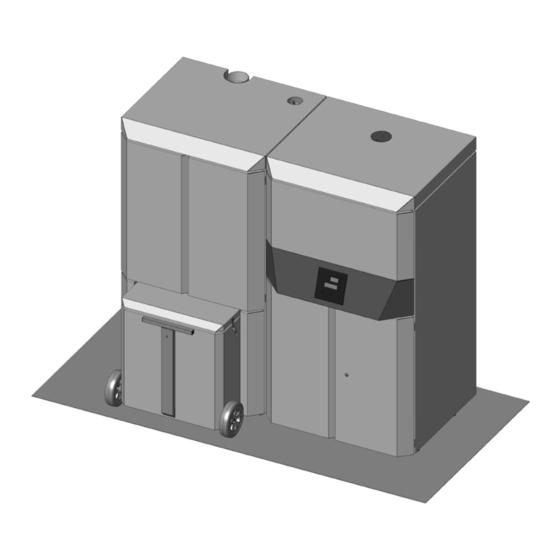
4 - UNPACKING PREPARATION AND UNPACKING The LOGIKA boiler is delivered inclusive of all if electrical and mechanical components and already tested at the factory: Install the boiler in the area set aside for it, making sure it conforms to the requirements. The body of the boiler must only ever be carried upright with a trolley. - Page 21 TOOLS: 10 mm face or box spanner FRONT VIEW REAR VIEW FIGURE 1 - STRUCTURE OF LOGIKA 25-35 BOILER REMOVAL SCREWS OF PACKAGE Open the package and remove the two front and back brackets, removing the two screws between each bracket and the boiler and the two screws that fasten the bracket to the pallet.
- Page 22 Open the package and remove the two screws between the bracket and the boiler and the two screws that fasten the bracket to the pallet. FIGURE 2 - LOGIKA 25-35 BOILER MANUAL TANK FIGURE 2 - LOGIKA 25-35 BOILER REFILL TANK...
-
Page 23: Technical Dept. - All Rights Reserved - Reproduction Is Prohibited
4 - UNPACKING EASYCLEAN KIT PACKAGE AUTOMATIC TURBOLATOR KIT ACTUATOR FEEDER PLASTIC CAP AUTOMATIC ASH OUTLET KIT • EASYCLEAN ASH OUTLET KIT ASH DOOR SUPPORT 2 X PIECES (see piece "a" page 34) MICROSWITCH SUPPORT BRACKET 1 X PIECE (see piece page 35) CENTRAL DOOR SUPPORT 1 X PIECE (see piece "b"... -
Page 24: Positioning
5 - POSITIONING REQUIREMENTS FOR INSTALLATION OF THE PLANT - POSITIONING The most important thing to do before installation of the LOGIKA boiler is to set aside a suitable area that meets the minimum requirements for installation. • the minimum clearance in front of the product for the purpose of cleaning, maintenance, etc. must be 1000 mm; the minimum permissible distance between the back of the product and a wall must be 400 mm;... - Page 25 5 - POSITIONING FOOT ADJUSTMENT Adjustable feet are mounted at the point of the wheels on the base of the boiler and tank. It is possible to unscrew the foot with a spanner to stabilise the structure. 1. TURN THE FEET CLOCKWISE TO LOWER THE PRODUCT. FOOT 2.
-
Page 26: Installation And Assembly Of Boiler
6 - INSTALLATION AND ASSEMBLY OF BOILER Instructions on how to install the structure of the LOGIKA boiler: a. Positioning on the ground (lifting or slide). b. Put the tank and boiler in the room where they are to be installed (but NOT in their definitive position). c. - Page 27 6 - INSTALLATION AND ASSEMBLY OF BOILER 2) using the slide (sold as an accessory). Put the slide against the pallet and fasten it on with the two screws at pos. x in the figure, aligning it with the wheels of the boiler. The slide can be fastened onto the pallet with the screws removed from the brackets that previously held the boiler on the pallet.
- Page 28 6 - INSTALLATION AND ASSEMBLY OF BOILER c) Install any additional kits (automatic turbolators and/or automatic ash outlet). Certain parts have to be removed in order to install the automatic ash cleaning kit. Remove from the boiler structure unit: • Ash drawer A and B • Doors C and D • unit F • unit E...
- Page 29 6 - INSTALLATION AND ASSEMBLY OF BOILER Remove both the augers (K) from the package containing the automatic ash cleaning kit. At this point, remove screw "h" (spanner 10) and remove carrier "g". Attention!! The auger is now no longer secured. To move it, hold it at the front with one hand to avoid dropping it. Technical Dept.
- Page 30 6 - INSTALLATION AND ASSEMBLY OF BOILER Undo the screws "j" to remove panel "k" at the back of the boiler. Remove the two caps "z" (using a 25 mm spanner or adjustable pliers).
- Page 31 6 - INSTALLATION AND ASSEMBLY OF BOILER Insert both the auger units (K), making sure the shaft of the auger does not slide at the front. Remove the two gaskets "j" and put them in again after assembling the doors "c" (see page 34). Technical Dept.
- Page 32 6 - INSTALLATION AND ASSEMBLY OF BOILER It is necessary to put the auger all the way into the structure of the boiler (see figure 1) in order to prevent the shaft of the auger from coming out of the hole at the back. Next, secure the shaft by re-inserting the carrier "g" and the screw "h" which were removed before the auger was inserted in the structure of the boiler.
- Page 33 6 - INSTALLATION AND ASSEMBLY OF BOILER Turn the auger by hand to move the screw "h" to a 90 degree angle to the vertical. 90° Repeat this operation with the other auger. 3 mm ~10 mm FIG. 1 - APPROX. 10 MM – CORRECT POSITIONING OF THE FEED SCREW Technical Dept.
- Page 34 6 - INSTALLATION AND ASSEMBLY OF BOILER Take the geared motors "m" out of the package of the trolley drawer. Make sure that the screw is securely fastened on the ground side (see detail "u") of the shaft of the geared motor, to prevent it from turning on empty.
- Page 35 6 - INSTALLATION AND ASSEMBLY OF BOILER In the accessories kit there is also a cable for connecting the geared motors "m". It is necessary to insert the terminal in the remote board "t" and the fastons in the geared motor "m". Caution! While the terminal for the remote board "t"...
- Page 36 6 - INSTALLATION AND ASSEMBLY OF BOILER The two doors and brackets in the Easyclean kit are pre-assembled in the interest of ease. They need to be disassembled, however, to make them easier to install. Take the two side brackets "a" and fasten them onto the structure of the boiler with the screws provided in the kit using the top and bottom holes (spanner 17).
- Page 37 6 - INSTALLATION AND ASSEMBLY OF BOILER Pull the cable about 30 cm out from the side. Take the micro-switch from the accessory package kit and, before fastening it onto the ash tray, remove the two screws “v” and low box “s”. Feed the cable from the left side of the boiler through the hole in the box “s” and connect it to the microswitch.
- Page 38 6 - INSTALLATION AND ASSEMBLY OF BOILER At the back of the boiler, connect the cable from the side to the terminal of the board as shown. The microswitch is now connected. 1 - Remove the bridge. 2 - Insert the cable from side “f”...
- Page 39 6 - INSTALLATION AND ASSEMBLY OF BOILER Take the two columns from the trolley package. Insert the seat at the base of the column with the screw of the boiler. At the top, fasten the column onto the structure with the screw provided. ATTENTION: This operation can be done when both the sides of the boiler are available.
- Page 40 6 - INSTALLATION AND ASSEMBLY OF BOILER When the additional kit for automatic tubulators is also present. The operations to be done are: Remove the protection "z" (detail G) from the left-hand side of the boiler, undoing the 4 screws "x". •...
- Page 41 6 - INSTALLATION AND ASSEMBLY OF BOILER • Calibrate the actuator. Set up the limit switch before inserting the actuator on the pin of the boiler 1. Press the clutch key and turn the vise anti-clockwise to the end of the scale. 2.
- Page 42 • This cable comes out from the rear bottom part of the boiler. Take the three red, white and black wires and connect them to the terminal with reference to the colours of the other three wires already in place.
- Page 43 Remove the terminals and connect the wires to the feeder as shown in the diagram: A = black wire to connect to V- B = red wire to V+ C = blue wire to neutral N D = brown wire to L •...
- Page 44 6 - INSTALLATION AND ASSEMBLY OF BOILER d) assembly of the right-hand side of the boiler (OBLIGATORY before connecting the boiler to the tank). Take hold of the right-hand side "Z" and put it up against the boiler. The side to be used is easily recognisable because it has a hole in the middle.
- Page 45 6 - INSTALLATION AND ASSEMBLY OF BOILER When installing the side of the boiler make sure the pin on side “x” engages in slot “f” at the back of the boiler. Fasten the panel at the top with the two screws provided. Assemble the two rubbers "k"...
- Page 46 6 - INSTALLATION AND ASSEMBLY OF BOILER f) assembly of the smoke pipe and lambda probe Take the packages containing the pipe and lambda probe out of the firebox holder in the boiler. Assemble the probe on the probe as follows: •...
- Page 47 6 - INSTALLATION AND ASSEMBLY OF BOILER g) assemble the lambda probe and connect it to the boiler connector. Connect the piston pin of the probe on the connector at the top of the boiler. h) connect the pressure gauge pipe to the pressure outlet. Connect the transparent pipe from the top part of the boiler to the pressure connector.
-
Page 48: Installation And Assembly Of Tank
7 - INSTALLATION AND ASSEMBLY OF TANK Instructions on how to install the structure of the tank: a. Positioning on the ground (lifting or slide). b. Put the tank in the room where it is to be installed (but NOT in its definitive position). c. - Page 49 7 - INSTALLATION AND ASSEMBLY OF TANK 2) using the slide (sold as an accessory). Put the slide against the pallet and fasten it on with the two screws at pos. x in the figure, aligning it with the wheels of the tank. The slide can be fastened onto the pallet with the screws removed from the brackets that previously held the tank on the pallet.
- Page 50 7 - INSTALLATION AND ASSEMBLY OF TANK MANUAL TANK Same procedure as for the Refill tank. Put the choice of tank (Refill or manual) in the installation area and with reference to the definitive measurements recommended above (see page 22)
- Page 51 7 - INSTALLATION AND ASSEMBLY OF TANK c) assembly of left side of the tank (manual/refill) (OBLIGATORY before connecting the tank to the boiler). Take the left side "S" and put it next to the tank. The side to be used is easily recognisable because it has two holes in the middle. At the base of the panel are two holes "x"...
- Page 52 7 - INSTALLATION AND ASSEMBLY OF TANK ASSEMBLY OF SIDE PANEL (MANUAL TANK)
- Page 53 Remove the flexible pipes. • Find the gasket "k" (provided). • Identify the flexible pipe with red marking "u" and connect it to the relative one of the boiler using gasket "k". Technical Dept. - All rights reserved - Reproduction is prohibited...
- Page 54 7 - INSTALLATION AND ASSEMBLY OF TANK e) mechanical connection between tank and boiler Put the tank and boiler in their definitive position. Next, connect the tank to the boiler with the four screws "x" already mounted on the boiler.
- Page 55 7 - INSTALLATION AND ASSEMBLY OF TANK f) insertion of spark plug Locate the spark plug loosely fitted in the tank and insert it fully, and fasten it in place with the two screws provided, as shown in the figure. Apply gentle pressure to counteract the resistance of the spring and push the flange all the way down onto the structure. DETAIL OF FASTENING OF SPARK PLUG (MANUAL TANK) DETAIL OF FASTENING OF SPARK PLUG (REFILL TANK) Technical Dept.
- Page 56 7 - INSTALLATION AND ASSEMBLY OF TANK g) electrical and hydraulic connection of the control panel to the tank Manual tank Locate the main instrument panel "P" with control panel "n" and pressure gauge "m" which is in the tank package, and proceed with electrical and hydraulic installation.
- Page 57 7 - INSTALLATION AND ASSEMBLY OF TANK Refill tank Connection of control panel. CENTRAL PANEL WITH CONTROL PANEL AND PRESSURE GAUGE (refill ELECTRICAL CONNECTION OF CONTROL PANEL (refill tank) tank) POSITION FOR ELECTRICAL CONNECTION OF CONTROL PANEL (refill tank) Technical Dept. - All rights reserved - Reproduction is prohibited...
- Page 58 7 - INSTALLATION AND ASSEMBLY OF TANK Connection of pressure gauge. a) Remove fitting "R" from the tip of the capillary "C". b) Unscrew fitting "T" on the hydraulic unit. c) Insert fitting "T" on the capillary by means of the slot. d) Screw fitting "T"...
- Page 59 7 - INSTALLATION AND ASSEMBLY OF TANK h) electrical connection between tank and boiler Connect the two piston pins of the tank to the piston pins of the boiler. The connection of the piston pin on the boiler is recognisably different (see image below).
-
Page 60: Assembly Of Boiler Aesthetics Unit
8 - ASSEMBLY OF BOILER AESTHETICS UNIT i) hydraulic connection between tank and water mains (supply-return-sanitary-filling) (RESPONSIBILITY OF SPECIALISED HYDRAULIC TECHNICIAN) l) hydraulic supply to boiler and checking for leaks (RESPONSIBILITY OF SPECIALISED HYDRAULIC TECHNICIAN). k) assembly of aesthetics unit of boiler After completing steps "i"... - Page 61 8 - ASSEMBLY OF BOILER AESTHETICS UNIT First of all, locate the left side panel "5" and fasten it onto the structure of the boiler. At the bottom, fit the holes "o" in the side on the pins ''p'' of the boiler. At the top of the panel, instead, insert the two flaps ("h") in the gaps (detail "t") and fasten them on with the two screws.
- Page 62 8 - ASSEMBLY OF BOILER AESTHETICS UNIT After fastening the left panel on the boiler, locate the top cover "7" and feed the pins "s" above the two side panels of the boiler into the fittings "v" at the base of cover "7". ASSEMBLY OF TOP COVER OF BOILER...
- Page 63 8 - ASSEMBLY OF BOILER AESTHETICS UNIT At this point, locate the two top doors "1" and "2" and fasten them onto the boiler. Doors "1" and "2" are already fitted with hinges. Fasten the two hinges "z" onto the structure of the boiler using the holes "g" and screws provided in the package of the manual/refill tank. Tools: Screwer with cross insert "a"...
- Page 64 8 - ASSEMBLY OF BOILER AESTHETICS UNIT If the Easyclean kit is not available, repeat this procedure for the two bottom doors "3" and "4". In this case, too, doors "3" and "4" are already fitted with hinges. Fasten the two hinges "n" onto the structure of the boiler at the point of the holes "m". ASSEMBLY OF BOTTOM DOOR OF BOILER...
-
Page 65: Assembly Of Trolley
9 - ASSEMBLY OF TROLLEY m) if the easyclean kit is present, assemble the trolley drawer. Complete the assembly of the automatic ash outlet kit by inserting the trolley. • To facilitate the operation, at least for the first few times, remove the door "z" (FIGURE A) of the trolley to permit better visibility. •... - Page 66 9 - ASSEMBLY OF TROLLEY • Open doors "1" and "2". • Hold the trolley with both hands and move it up to the structure of the boiler (FIGURE 1). • Engage the intakes of the trolley in the two protruding augers (FIGURE 2). •...
-
Page 67: Assembly Of Aesthetics Unit Of Refill Tank
10 - ASSEMBLY OF AESTHETICS UNIT OF REFILL TANK n) assembly of aesthetic unit of tank Refill tank REFILL TANK AESTHETICS UNIT For convenience, the panels are identified with the numbers in the picture. Technical Dept. - All rights reserved - Reproduction is prohibited... - Page 68 10 - ASSEMBLY OF AESTHETICS UNIT OF REFILL TANK Locate the right side panel "11" and insert the holes "y" at the base of the panel on the pins "k" on the structure of the tank. ASSEMBLY OF RIGHT-HAND SIDE PANEL (REFILL TANK)
- Page 69 10 - ASSEMBLY OF AESTHETICS UNIT OF REFILL TANK The central instrument panel "E" with control panel and pressure gauge has already been connected to the hydraulic kit and printed circuit board (see dedicated pages). Once the right panel has been mounted, it can be assembled on the structure of the tank by engaging parts "g"...
- Page 70 10 - ASSEMBLY OF AESTHETICS UNIT OF REFILL TANK The top panel "9" has the same fastening system as central panel "E". Insert the hooks "g" in the holes "f" on the structure of the tank. Use screw "y" (provided) to secure the top of the panel "9". ASSEMBLY OF TOP PANEL (REFILL TANK)
- Page 71 10 - ASSEMBLY OF AESTHETICS UNIT OF REFILL TANK The bottom door "A" is already fitted with hinges (detail "t") to be fastened onto the structure of the tank using the holes present (detail "u") and the screws provided. ASSEMBLY OF DOOR (REFILL TANK) IMPORTANT: Door "8"...
- Page 72 10 - ASSEMBLY OF AESTHETICS UNIT OF REFILL TANK In order to fasten cover “12” already fitted with hinges (detail “t”) it is necessary to fasten it first to the holes “u” in the structure of the tank (with the screws provided) then engage the ring on piston “x” on pin “z”. Repeat this procedure for the second piston. ASSEMBLY OF DOOR (REFILL TANK)
-
Page 73: Assembly Of Aesthetics Unit Of Manual Tank
11 - ASSEMBLY OF AESTHETICS UNIT OF MANUAL TANK MANUAL TANK For convenience, the panels are identified with the numbers in the picture. MANUAL TANK AESTHETICS UNIT Technical Dept. - All rights reserved - Reproduction is prohibited... - Page 74 11 - ASSEMBLY OF AESTHETICS UNIT OF MANUAL TANK Locate the right side panel ''12'' and insert the holes ''y'' at the base of the panel on the pins ''k'' on the structure of the tank. ASSEMBLY OF RIGHT-HAND SIDE PANEL (MANUAL TANK)
- Page 75 11 - ASSEMBLY OF AESTHETICS UNIT OF MANUAL TANK The central instrument panel ''p'' with control panel and pressure gauge has already been connected to the hydraulic kit and printed circuit board (see dedicated pages). After assembling also the right panel with holes "s" it is possible to install it on the structure of the tank by engaging the parts "t".
- Page 76 11 - ASSEMBLY OF AESTHETICS UNIT OF MANUAL TANK The top panel ''10'' has the same fastening system as central panel ''p'' . Insert the hooks ''g'' in the holes ''f'' on the structure of the tank. Use screw ''y'' (provided) to secure the top of the panel ''10'' . ASSEMBLY OF TOP PANEL (MANUAL TANK)
- Page 77 11 - ASSEMBLY OF AESTHETICS UNIT OF MANUAL TANK At this point, locate the two bottom doors "8" and "9" and fasten them onto the structure of the tank. Doors ''8'' and ''9'' are already fitted with hinges. Fasten the two hinges “t” onto the structure of the tank at the point of the holes ''u'' . Doors “8”...
- Page 78 11 - ASSEMBLY OF AESTHETICS UNIT OF MANUAL TANK Fasten the rear panel "14" onto the structure of the tank with the screws provided. ASSEMBLY OF REAR PANEL (MANUAL TANK)
- Page 79 11 - ASSEMBLY OF AESTHETICS UNIT OF MANUAL TANK In order to fasten the cover ''13'' , which is already fitted with hinges (detail ''t''), attach it first to the holes (detail ''u'') on the structure of the tank (with the screws provided) and then engage the ring of the piston ''x'' on pin ''z'' . Repeat the procedure for the second piston. ASSEMBLY OF COVER (MANUAL TANK) o) hydraulic connection between the tank and water mains (RESPONSIBILITY OF A SPECIALIST TECHNICIAN) It is advisable to connect the tank and system with flexible pipes.
- Page 80 Via La Croce n°8 33074 Vigonovo di Fontanafredda (PN) – ITALY Telefono: +39 0434/599599 r.a. Fax: +39 0434/599598 Internet: www.mcz.it e-mail: info.red@mcz.it 8901231800 REV. 0 20/11/2012...
- Page 81 INSTALLATION GUIDE PELLET BOILER LOGIKA 25-35 LOGIKA 25-35 REFILL PART 2 - OPERATION AND CLEANING Translation of the original instructions...
-
Page 82: Table Of Contents
TABLE OF CONTENTS TABLE OF CONTENTS ..................II 1 - PLUMBING CONNECTION ................1 2- FILLING THE SYSTEM .................. 2 3 - GENERAL WARNINGS ................. 4 4 - LOADING THE PELLETS ................7 2 - MENU OPTIONS ..................9 6 - ADJUSTMENTS MENU ................17 7 - SYSTEM CONFIGURATION ................18 8 - ELECTRICAL CONNECTION .................22 9 - START-UP/SHUT-DOWN ................23... -
Page 83: Plumbing Connection
1 - PLUMBING CONNECTION PLUMBING CONNECTION IMPORTANT: The connections depend on the type of hydraulic kit installed and the type of system configuration. IMPORTANT! The boiler must be installed by qualified personnel who can testify to the conformity of the system in accordance with the applicable laws in force. -
Page 84: Filling The System
2- FILLING THE SYSTEM FILLING THE SYSTEM Fill the system slowly to allow air bubbles to pass through the vent holes of the heating system. For closed circuit heating systems, the filling pressure of the system at cold and the pre-inflation pressure of the expansion tank must be the same. •... - Page 85 2- FILLING THE SYSTEM Fill the heating system manually using the tap with check valve in the hydraulic kit. • Connect or plug the H O hot outlet "U". • Connect the H O cold input "K" to the system. •...
- Page 86 3 - GENERAL WARNINGS GENERAL PRECAUTIONS The electrical safety of the system is guaranteed only when this is connected correctly to an efficient earthing system installed in accordance with the safety standards in force: the pipes of the gas, water and heating systems do not constitute a suitable earth system. It is necessary to ensure this essential safety requirement;...
- Page 87 3 - GENERAL WARNINGS BEFORE START-UP GENERAL PRECAUTIONS After a long period of inactivity, use a vacuum cleaner with long tube to remove any traces of pellets in the tank that could have absorbed humidity and are no longer suitable for combustion. The first start-up may not be successful as the feed screw is empty and does not always manage to load the required amount of pellets in the brazier to reach the threshold temperature, despite the presence of fire.
-
Page 88: General Warnings
3 - GENERAL WARNINGS OPENING/CLOSING THE DOOR OF THE FIREBOX ATTENTION! The door of the firebox should be opened only when the boiler is cold and at standstill, and only when removing the ash. The door must be closed properly for the boiler to work correctly. OPENING THE DOOR OF THE FIREBOX To open the internal door, lift and pull the handle towards yourself. -
Page 89: Loading The Pellets
4 - LOADING THE PELLETS LOADING THE PELLETS The pellets can be loaded either manually or automatically. The tank can contain up to 210 litres or 140 kg of pellets. Manual loading (Logika): • Open the top cover of the tank and pour in the pellets. In the interest of convenience, it is possible to put the bag (15 kg) on the grate and cut it. - Page 90 4 - LOADING THE PELLETS AUTOMATIC PELLET LOADING OF LOGIKA REFILL Refer to section 3 of the manual for automatic pellet loading with the BIG-BAG system. AUTOMATIC LOADING OF LOGIKA REFILL...
-
Page 91: Menu Options
2 - MENU OPTIONS 2 - MENU OPTIONS CONTROL PANEL DISPLAY Menu options 1. Scrolling up through the programming menu. 5. Decrease set / programming functions 2. Scrolling down through the programming menu 6. Start/stop boiler/exit menu 3. Menu/confirmation. 7. Display. 4. - Page 92 2 - MENU OPTIONS CONFIGURATION OF PROGRAMMED MODE (TIMER) - Main menu The current time and date must be configured to ensure correct operation of the timer. There are six configurable TIMERS; for each one, the user can select a start and stop time and the days of the week when it is in use. When one or more programs are active, the status of the boiler and the TIMER "n"...
- Page 93 2 - MENU OPTIONS NOTES ON USE OF THE TIMER • The start time can be between 00:00 and 23:50 • If the stop time has not yet been saved, the program proposes a start time at +10 minutes. • If a timer program stops the boiler at 24:00 on one day and another program starts it up at 00:00 on the next day: the boiler remains •...
- Page 94 2 - MENU OPTIONS a - Language Select the language as follows: • Press the "menu" key. • Use the arrow keys to scroll through and select "Settings" • Press “menu” to confirm. • Use the arrow keys to scroll through and select "language". •...
- Page 95 2 - MENU OPTIONS d - Auto-Eco The Auto-Eco function turns the boiler off automatically at the configured time of the "Eco Stop T" parameter when no heat is required by the devices connected to the boiler: external thermostat (configurations 1-2-3), flow switch (configuration 2), thermostat/puffer probe (configuration 5-6) or thermostat/boiler probe (configuration 3-4).
- Page 96 2 - MENU OPTIONS g - Pellet Recipe This function is for adapting the boiler to the type of pellet in use. As there are many types of pellet available on the market, the operation of the boiler can vary considerably according to the quality of the fuel. When the pellets clog up the brazier due to excess loading of fuel or when the flames are high even at low power, or when the flames are low, it is possible to decrease/increase the amount of pellets in the brazier: Available values:...
- Page 97 2 - MENU OPTIONS i - Component test This can be done only when the boiler is off and allows you to select the components to be tested: • Spark plug: runs for a test time during which the panel shows the countdown timer in seconds. •...
- Page 98 2 - MENU OPTIONS l - System configuration (see dedicated chapter) Modify the system configuration (with the boiler off) as follows: • Press the ''menu'' key. • Use the arrow keys to scroll through and select "Settings" • Press 3 “menu” to confirm. •...
-
Page 99: Adjustments Menu
6 - ADJUSTMENTS MENU ADJUSTMENTS MENU Press the + or - keys (keys 4 or 5) to access the menu for changing the temperature settings of the set system configuration. Configuration 1-2-3-4-5 Water temperature in boiler Configuration 4 Boiler water temperature Configuration 6 Puffer water temperature Edit as follows: • + or - key... - Page 100 7 - SYSTEM CONFIGURATION SYSTEM CONFIGURATIONS At the time of installation, the product must be configured according to the type of system by selecting the relative parameter in the technical menu. There are 6 possible configurations, described below: Configuration Description Ambient temperature management with external ambient thermostat Ambient temperature management with external ambient thermostat;...
- Page 101 7 - SYSTEM CONFIGURATION CONFIGURATION 2 (FACTORY SETTING) CONFIGURATION 3 Technical Dept. - All rights reserved - Reproduction is prohibited...
- Page 102 7 - SYSTEM CONFIGURATION CONFIGURATION 4 CONFIGURATION 5 NOTE: TO ENSURE CORRECT OPERATION IN THIS CONFIGURATION, THE PUFFER THERMOSTAT HAS TO BE SET AT A VALUE BELOW THE "WATER T SET".
- Page 103 7 - SYSTEM CONFIGURATION CONFIGURATION 6 LOGIKA BOILER HEATING DELIVERY HEATING RETURN ZONE VALVE HEATING BODIES HOT SANITARY WATER COLD SANITARY WATER SANITARY WATER BOILER DIVERTER VALVE BOILER THERMOSTAT THERMOSTATIC MIXER VALVE NTC PROBE 10 kΩ β3434 SANITARY WATER HEATING PUFFER HEATING SYSTEM CIRCULATOR PUFFER THERMOSTAT NTC PROBE 10 kΩ...
-
Page 104: Electrical Connection
8 - ELECTRICAL CONNECTION AUXILIARY BOILER Positions 6-7 have a N.C. contact (Max 3A) for enabling an auxiliary boiler when the pellet boiler is turned off or in alarm mode. ELECTRICAL CONNECTIONS 1 2 3 4 5 6 7 8 9 10 TERMINAL BLOCK CONTACTS POS.1-2 EXTERNAL THERMOSTAT/PUFFER THERMOSTAT CLEAN POS.8 NEUTRAL THREE-WAY VALVE 230 Vac... - Page 105 9 - START-UP/SHUT-DOWN START-UP Press key 6 (esc) to start up. The display on the panel is ON with the flame blinking. When the flame stops blinking, the boiler has reached the operating condition for "supplying power". SUPPLY OF POWER The boiler positions itself at flame level 3 at the end of the ignition phase Subsequent modulation of the flame to lower or higher power is controlled automatically on the basis of the heat requirements of the connected devices and on the basis of the set system...
-
Page 106: Safety Devices And Alarms
10 - SAFETY DEVICES AND ALARMS SAFETY DEVICES The product is supplied with the following safety devices: SMOKE PRESSURE GAUGE Monitors pressure in the smoke duct. It is designed to shut down the boiler in the event of an obstructed flue or significant back-pressure (from the wind). - Page 107 10 - SAFETY DEVICES AND ALARMS TAMPERING WITH THE SAFETY DEVICES IS PROHIBITED If the product is NOT used as described in this instruction manual, the manufacturer declines all liability for any damage caused to persons and property. The manufacturer furthermore refuses to accept responsibility for damage to persons and property arising from the failure to observe all the rules contained in the manual and in particular: •...
- Page 108 10 - SAFETY DEVICES AND ALARMS ALARM SIGNALLING When a condition occurs other than the one expected for regular operation of the boiler, an alarm is triggered. The reason for the alarm is given on the control panel. The sound signal is not enabled for alarms A01-A02 in order not to disturb the user when there is an absence of pellets in the night tank.
- Page 109 10 - SAFETY DEVICES AND ALARMS Fault with puffer probe. Puffer probe detached / interrupted / defective / not recognised. Call the assistance centre. Puffer probe alarm Fault with puffer probe 2. Puffer probe detached / interrupted / defective / not recognised.
-
Page 110: Maintenance And Cleaning
11 - MAINTENANCE AND CLEANING WEEKLY AND MONTHLY CLEANING PERFORMED BY THE USER BEFORE EACH START-UP All cleaning must be carried out with the boiler cold. Before cleaning the boiler check that it is equipped with the Easy Clean kit (automatic discharge of ash and/or automatic turbolators). In the case of a Logika boiler without Easy Clean kit, proceed as follows: • move the lever on the left side of the boiler forcefully 3-4 times to start cleaning of the turbolators and to make any ash deposits fall into the drawers. - Page 111 11 - MAINTENANCE AND CLEANING • open the door on the firebox and use an iron pallet to move any residual ash into the hole of the firebox. In this way, the ash is deposited in the bottom ash drawers by the end of the automatic cleaning phase. • enable the cleaning function This function can be enabled only when the stove is off.
- Page 112 11 - MAINTENANCE AND CLEANING At the end of the cleaning cycle: • Open the bottom aesthetic doors • Remove the ash tray "K" from under the boiler. • Open the doors of the boiler. • Remove the ash drawers. •...
- Page 113 11 - MAINTENANCE AND CLEANING In the case of a Logika boiler with Easy Clean kit, proceed as follows: • clean the turbolators manually as described previously, if the boiler does not feature the automatic turbolator kit; and if it does feature this kit, cleaning occurs automatically upon each ignition of the boiler (so, every 24 hours).
- Page 114 11 - MAINTENANCE AND CLEANING ATTENTION: The frequency with which the smoke exhaust system must be cleaned depends on the use of the boiler and the type of installation. We recommend relying on an authorized service centre for end-of-season cleaning and maintenance, they will carry out all of the previously mentioned work and make a general check of the stove's components.
- Page 115 11 - MAINTENANCE AND CLEANING PARTS/INTERVAL 2-3 DAYS WEEKLY 30 DAYS 60 DAYS EVERY SEASON · Manual cleaning of turbolators (1) Cleaning of firebox Cleaning the bottom ash drawers (2) Cleaning the trolley (3) Cleaning the outlet "T" (outside the boiler) Cleaning the smoke fitting Checking the circulation pump...
- Page 116 12 - TROUBLESHOOTING CHECKING THE INTERNAL COMPONENTS ATTENTION: All operations that require repairs must be carried out solely by a specialist technician with the boiler extinguished, cold and with the power cord unplugged. ANOMALY POSSIBLE CAUSES SOLUTIONS The pellets are not fed into the The pellet hopper is empty Fill the hopper with pellets combustion chamber.
-
Page 117: Troubleshooting
12 - TROUBLESHOOTING ANOMALY POSSIBLE CAUSES SOLUTIONS The boiler runs for a few minutes and Start-up phase is not completed Repeat start-up then goes out. Temporary power cut Wait for the automatic restart Clogged smoke duct Clean the smoke duct Faulty or malfunctioning temperature Check and replace the probes probes... - Page 118 12 - TROUBLESHOOTING ANOMALIES RELATED TO THE PLUMBING CIRCUIT No increase in temperature with Incorrect combustion adjustment. Check recipe and parameters. boiler in operation Boiler / system dirty. Check and clean the boiler. Insufficient stove power. Check that the boiler is properly sized for the requirements of the system.
-
Page 119: Wiring Diagram
13 - WIRING DIAGRAM REMOTE BOARD NR. 24 Comune Apri Apri Comune Chiudi Chiudi VENTILATORE FUMI TRASFORMATORE 230 V ac 24 V dc Technical Dept. - All rights reserved - Reproduction is prohibited... - Page 120 13 - WIRING DIAGRAM MOTHERBOARD NR. 25 3 vie solare valvole zona 2 Pompa solare Valvola zona 1 ENCODER COCLEA OUT PWM Pompa SERIALE-SERAMI...
- Page 124 Via La Croce n°8 33074 Vigonovo di Fontanafredda (PN) – ITALY Telephone: +39 0434/599599 r.a. Fax: +39 0434/599598 Internet: www.mcz.it e-mail: info.red@mcz.it 8901249300 REV. 0 17/11/2012...
Need help?
Do you have a question about the LOGIKA 25-35 and is the answer not in the manual?
Questions and answers