Table of Contents
Advertisement
Advertisement
Table of Contents

Related Manuals for RED practika 28-33


Summary of Contents for RED practika 28-33
- Page 1 USE AND INSTALLATION MANUAL COD.8901112700...
-
Page 2: Table Of Contents
3. TECHNICAL SPECIFICATIONS AND DIMENSIONS ..............9 3.1. Technical specifications ......................9 3.2. Description of the Practika 28-33 hot water boiler and automatic pellet burner ......10 3.3. Description of the “Practika” hot water pellet boiler heat exchanger .......... 10 3.4. - Page 3 External thermostat 7.4.1......................42 7.5. Installing the pellet conveyor auger ..................42 Filling the pellet conveyor auger with fuel 7.5.1................42 7.6. Connect the boiler control box to the power supply ..............42 7.7. End view of the system ......................43 8.
-
Page 4: General Information
Chapter 1 PRACTIKA 28-33 USE AND INSTALLATION MANUAL page 4 General information The user is NOT permitted to service this boiler. The manufacturer cannot be held liable for personal injury, harm to animals or property damage resulting from failure to observe the instructions contained in the manuals supplied with the boiler. - Page 5 Appliance use in accordance with the envisaged purposes includes scrupulous observance of the instructions provided in this manual. RED reserves the right to make any changes to the design and factory settings of the burner and hot water boiler without having to inform the end users of such changes.
-
Page 6: Guarantee Terms
Chapter 2 PRACTIKA 28-33 USE AND INSTALLATION MANUAL page 6 2. GUARANTEE TERMS The Manufacturer guarantees the product, with the exception of parts subject to normal wear specified below, for two years from the date of purchase, provided that proof of purchase is supplied in a document specifying the name of the retailer and the date the sale was made and that the completed guarantee certificate was sent within 8 days of said purchase. -
Page 7: Additional Clauses
Please contact your retailer and/ or local importer in the event of product failure. RED will not be held liable for any damage which may - either directly or indirectly - be caused to property, or personal injury or harm to animals ensuing from failure to observe all the instructions provided herein and the applicable regulations regarding installation, use and maintenance of the appliance. -
Page 8: Service Call
Chapter 2 PRACTIKA 28-33 USE AND INSTALLATION MANUAL page 8 2.7. Service call The service call must be made to the retailer or service centre. The manufacturer cannot be held liable if the product and any of its accessories are used incorrectly or modified without authorisation. -
Page 9: Technical Specifications And Dimensions
Chapter 3 PRACTIKA 28-33 USE AND INSTALLATION MANUAL page 9 3. TECHNICAL SPECIFICATIONS AND DIMENSIONS 3.1. Technical specifications The hot water pellet boilers in the "PRACTIKA" range are pellet boilers for the production of hot water with a steel structure, which use solid biomasses in the form of pellets as fuel. The boiler is designed for connection to hot water heating systems. -
Page 10: Description Of The Practika 28-33 Hot Water Boiler And Automatic Pellet Burner
Chapter 3 PRACTIKA 28-33 USE AND INSTALLATION MANUAL page 10 3.2. Description of the Practika 28-33 hot water boiler and automatic pellet burner The system consists of: Hot water pellet boiler Automatic pellet burner 3.3. Description of the “Practika” hot water pellet boiler heat exchanger The "PRACTIKA"... - Page 11 Chapter 3 PRACTIKA 28-33 USE AND INSTALLATION MANUAL page 11 The heat exchanger is a welded structure of steel plates. The front section of the heat exchanger consists of a combustion chamber, beneath which the ash tray is situated. The heat exchanger is a relatively compact structure and it was designed like the so-called "three-way...
-
Page 12: System Technical Details
Chapter 3 PRACTIKA 28-33 USE AND INSTALLATION MANUAL page 12 3.4. System technical details The heat and technical details of the system consisting of pellet boiler and pellet burner using wood pellets: Parameter Measurement unit Value Hot water pellet boiler model... - Page 13 Chapter 3 PRACTIKA 28-33 USE AND INSTALLATION MANUAL page 13 The dimensions and technical details of the system consisting of pellet boiler and pellet burner using wood pellets: Parameter Measurement unit Value Hot water pellet boiler model PRACTIKA 28 PRACTIKA 33...
- Page 14 Chapter 3 PRACTIKA 28-33 USE AND INSTALLATION MANUAL page 14 The following figures show the dimensions and structure of the system modules: Figure 3.4.1 Front view with burner on the left Figure 3.4.2 Top view with burner on the left Technical specifications and dimensions Technical dept.
- Page 15 Chapter 3 PRACTIKA 28-33 USE AND INSTALLATION MANUAL page 15 Ø150 Figure 3.4.3 Rear view with burner on the right Technical specifications and dimensions Technical dept. - All rights reserved - Reproduction prohibited...
- Page 16 Chapter 3 PRACTIKA 28-33 USE AND INSTALLATION MANUAL page 16 Upper boiler cover Convective ducting cover Upper front combustion chamber cover Combustion chamber flap cover Flange for pellet burner connection Fibreglass seal M10 fixing nuts Figure 3.4.4 View of the pellet boiler with burner on the right Technical specifications and dimensions Technical dept.
- Page 17 Chapter 3 PRACTIKA 28-33 USE AND INSTALLATION MANUAL page 17 Upper boiler cover Combustion gas outlet duct “Tertiary passage” of combustion gases through the boiler “Secondary passage” of combustion gases through the boiler “First passage” of combustion gases through the boiler...
-
Page 18: Information For Using Pellets
4100÷5000 kcal/kg). In order to prolong the life cycle of the boiler, RED recommends the use of good quality pellets. The pellets to be used to power the boiler must have high quality characteristics, such as those set out in standards DIN 51731 and ÖNORM M7135. -
Page 19: Installing A "Practika" Hot Water Boiler
Chapter 4 PRACTIKA 28-33 USE AND INSTALLATION MANUAL page 19 4. INSTALLING A "PRACTIKA" HOT WATER BOILER 4.1. General warnings This boiler must only be used for the use expressly intended. Any other use is to be considered incorrect and therefore dangerous. -
Page 20: Packaging
Chapter 4 PRACTIKA 28-33 USE AND INSTALLATION MANUAL page 20 4.2. Packaging The boiler is delivered complete with all electrical and mechanical components and it is factory tested. The boiler must always be handled vertically, using manual or mechanical cranes, which can lift the pallet on which it is packaged or the boiler itself directly. - Page 21 Chapter 4 PRACTIKA 28-33 USE AND INSTALLATION MANUAL page 21 above any structure adjacent to the chimney itself (including the ridge of the roof) at least 8 metres away. The flue pipe must have a diameter of no less than the boiler union; for flue pipes with a square or rectangular cross-section, the internal cross-section must be increased by 10% compared to the boiler union.
-
Page 22: Roof Outlet Via An External Steel Flue Pipe
Chapter 4 PRACTIKA 28-33 USE AND INSTALLATION MANUAL page 22 Avoid installing completely horizontal sections. The room where the heat generator is to be installed must not contain any existing or envisaged smoke suction hoods in order to avoid depressurising the setting. -
Page 23: Roof Outlet Along A Traditional Flue Pipe
Chapter 4 PRACTIKA 28-33 USE AND INSTALLATION MANUAL page 23 Roof outlet along a traditional flue pipe 4.4.2. The flue smoke can also be discharged using an existing traditional flue pipe provided it is compliant to standards (see UNI 10683). -
Page 24: System Installation Procedure
Chapter 5 PRACTIKA 28-33 USE AND INSTALLATION MANUAL page 24 5. SYSTEM INSTALLATION PROCEDURE 5.1. Characteristics and special requirements for fitting and installing the automatic pellet burner and the hot water pellet boiler The automatic pellet burner is connected and fitted onto the heat exchanger of the pellet boiler. The burner... -
Page 25: Hydraulic Connections
Chapter 5 PRACTIKA 28-33 USE AND INSTALLATION MANUAL page 25 The boiler must be fitted in a room that is sufficiently aired in order to guarantee there is alwas a continuous flow of air for combustion. Air inlets linked to the outside must be arranged and, in compliance with the provisions of Standard UNI 10683, these must have the following characteristics: 1. -
Page 26: Hydraulic Scheme
Chapter 5 PRACTIKA 28-33 USE AND INSTALLATION MANUAL page 26 5.4. Hydraulic scheme System installation procedure Technical dept. - All rights reserved - Reproduction prohibited... - Page 27 Chapter 5 PRACTIKA 28-33 USE AND INSTALLATION MANUAL page 27 Figure 5.4.1 General hydraulic scheme recommended for connecting the “PRACTIKA” pellet boiler to the heating system. System installation procedure Technical dept. - All rights reserved - Reproduction prohibited...
-
Page 28: Washing The System
Chapter 5 PRACTIKA 28-33 USE AND INSTALLATION MANUAL page 28 PRACTIKA BOILER THERMOSTATIC MIXER COLD WATER INLET SOLAR CONTROL UNIT SAFETY VALVE SOLAR PANEL SOLAR PUMP STATION CYLINDER DOMESTIC HOT WATER the system installation and the running of the tests must be specified in the relevant... - Page 29 This could damage the seals and cause noisy operation. RED will not be held liable for any damage to persons, animals or property caused by failure to observe the above instructions. Once all the hydraulic connections have been made, check the seals under pressure by filling the boiler.
-
Page 30: Electrical Connections
Chapter 5 PRACTIKA 28-33 USE AND INSTALLATION MANUAL page 30 5.6. Electrical connections General warnings 5.6.1. The electrical safety of the system is only ensured when the same is correctly connected to an efficient earthing system, built in accordance with the provisions of the applicable safety standards: the piping of the gas, plumbing and heating systems are absolutely not suitable. -
Page 31: Settings To Make Before The First Start-Up
Chapter 5 PRACTIKA 28-33 USE AND INSTALLATION MANUAL page 31 Connection to 230V electricity supply The installation of the electrical accessory components of the boiler requires electrical connection to a mains at 230 V – 50 Hz: This connection must be made according to best practice in accordance with the applicable CEI standards. -
Page 32: Wiring Diagram Of The Hot Water Pellet Boiler
Chapter 6 PRACTIKA 28-33 USE AND INSTALLATION MANUAL page 32 Wiring diagram of the hot water pellet boiler 5.6.3. Figure 5.6.3.1. General wiring diagram of the pellet boiler control panel 1. Control panel 9. Smoke blower fan rev control 2. Smoke sensor 10. -
Page 33: General Instructions
Chapter 6 PRACTIKA 28-33 USE AND INSTALLATION MANUAL page 33 6. GENERAL INSTRUCTIONS 6.1. Starting the system Press key B on the control panel. CAUTION: You may notice some smoke being released by the boiler when the system is started up, especially if the chimney flue does not have appropriate draft (for instance, insufficient height of the chimney flue or obstruction of the chimney flue outlet gas duct). -
Page 34: Checking The System Heat Output
Chapter 6 PRACTIKA 28-33 USE AND INSTALLATION MANUAL page 34 6.4. Checking the system heat output The system heat output check is performed by adjusting the heat output of the pellet burner. CAUTION: if the type of fuel changes (for instance, by changing the category of pellets, the supplier, the size, etc.), you will then need to adjust the heat output parameters and the burner operating mode. -
Page 35: Installation Of Boiler Components
Chapter 7 PRACTIKA 28-33 USE AND INSTALLATION MANUAL page 35 7. INSTALLATION OF BOILER COMPONENTS 7.1. Installing the automatic pellet burner Use the mineral wool insulation seal applied to the burner pellet. Avoid damaging the seal when connecting the burner to the boiler flange - this seal reduces the penetration of ambient air into the combustion chamber, as well as providing heat insulation, thereby reducing the backflow of heat towards the main burner module. -
Page 36: Installing The Two Ceramic Plates In The Boiler Combustion Chamber
Chapter 7 PRACTIKA 28-33 USE AND INSTALLATION MANUAL page 36 Figure 7.1.2 Side view of the pellet burner, fitted onto the boiler heat exchanger. 7.2. Installing the two ceramic plates in the boiler combustion chamber Fit the two ceramic plates in the boiler combustion chamber - they will guide the combustion gases and... -
Page 37: Installing The Combustion Gas Duct Cover
Chapter 7 PRACTIKA 28-33 USE AND INSTALLATION MANUAL page 37 Fit the second ash cover onto the bottom of the boiler convective wall Ash cover Figure 7.2.2 The ash cover is put in place (which covers the aperture for cleaning the ash between the secondary and tertiary duct of the heat exchanger combustion gases). - Page 38 Chapter 7 PRACTIKA 28-33 USE AND INSTALLATION MANUAL page 38 combustion cover correctly positioned Hook for the combustion gas cover (to handle it more easily) Lower support of the combustion gas cover (welded onto the heat exchanger) Figure 7.3.1 The correct position of the ducting cover is illustrated Installation of boiler components Technical dept.
- Page 39 Chapter 7 PRACTIKA 28-33 USE AND INSTALLATION MANUAL page 39 Installing the combustion gas duct cover Figure 7.3.2 Position of the hot water boiler covering elements Fir the heat exchanger convective ducting cover EXPLANATION: this cover comes with a stainless steel protective heat insulation plate.
- Page 40 Chapter 7 PRACTIKA 28-33 USE AND INSTALLATION MANUAL page 40 Fit the combustion chamber cover of the boiler heat exchanger EXPLANATION: this cover has a protective heat insulation plate, to to operate at the high temperature levels of the combustion gases in the boiler combustion chamber.
-
Page 41: Connect The Pellet Burner To The Hot Water Boiler
Chapter 7 PRACTIKA 28-33 USE AND INSTALLATION MANUAL page 41 7.4. Connect the pellet burner to the hot water boiler Connect the pellet burner cables to the boiler, inserting the burner connector into the boiler female connector. CAUTION: these electrical connectors come with an element that prevents inadvertent detachment of the connectors - do not force them, use a suitable tool to detach them. -
Page 42: External Thermostat
Chapter 7 PRACTIKA 28-33 USE AND INSTALLATION MANUAL page 42 EXTERNAL THERMOSTAT DOMOTIC 3/4/7 BOILER/ BURNER CONNECTION MANUAL RESET THERMOSTAT EXTRACTOR FAN (OPTIONAL) POWER SUPPLY External thermostat 7.4.1. The connection must be closed in order to start up the boiler. -
Page 43: End View Of The System
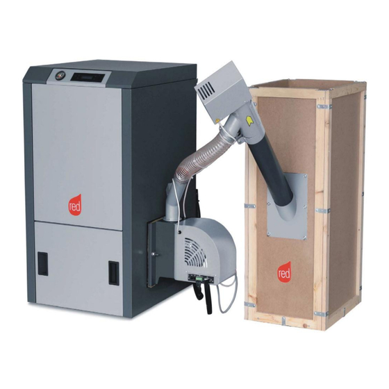
Chapter 7 PRACTIKA 28-33 USE AND INSTALLATION MANUAL page 43 7.7. End view of the system Figure 7.7.1 End view of the system consisting of the “PRACTIKA” hot water pellet boiler and pellet burner. Installation of boiler components Technical dept. - All rights reserved - Reproduction prohibited... -
Page 44: Control Panel Display
Chapter 8 PRACTIKA 28-33 USE AND INSTALLATION MANUAL page 44 8. CONTROL PANEL DISPLAY 8.1. Control panel logic Below is some useful information to understand the logic for browsing and using the control panel. The brightness of the control panel is turned off after approximately 30” if the keyboard is left unused. -
Page 45: Menu Structure
Chapter 9 PRACTIKA 28-33 USE AND INSTALLATION MANUAL page 45 9. MENU STRUCTURE The menu is designed to set/modify a series of information GENERAL MENU TIME SETTING Hour Minutes SETTINGS Language Auto eco (ON-OFF) ... -
Page 46: Hour/Minutes Adjustment
Chapter 9 PRACTIKA 28-33 USE AND INSTALLATION MANUAL page 46 9.1. Hour/minutes adjustment In the start screenshot, press any key to show the screenshot with the word MENU. Press the key relating to MENU to display the word SET. Enter SET to open the programme to change the:... -
Page 47: Eco Mode
Chapter 9 PRACTIKA 28-33 USE AND INSTALLATION MANUAL page 47 FOR EXAMPLE: Fire:5 Menu 65°C H2O 21.04 TH2O:75°C < Setting > < Setting > < Language > < Language > ECO mode 9.2.2. The boiler is factory set to AUTO-ECO mode, which means: when the external thermostat is satisfied, the boiler modulates at power level 1 for a brief period of time, after which - if the thermostat continues to be satisfied - the boiler shuts down. -
Page 48: Back Light
Chapter 9 PRACTIKA 28-33 USE AND INSTALLATION MANUAL page 48 Back light 9.2.3. This setting enables or disables the automatic switch-off of the backlit display. Tone (Panel display: ON-OFF) 9.2.4. This setting disables the sound when keys are pressed. It does not affect the alarm signals. -
Page 49: Temperature On Pump
Chapter 9 PRACTIKA 28-33 USE AND INSTALLATION MANUAL page 49 Temperature On Pump 9.2.9. Use this function to set the temperature for the circulation pump to come on. With the boiler on, with water at a temperature below the set point, the pump starts only for 10 seconds per minute, while with... -
Page 50: Start Pump
Chapter 9 PRACTIKA 28-33 USE AND INSTALLATION MANUAL page 50 Start Pump 9.2.13. This function manually starts the circulation pump to run the circulation test on the system. 9.3. Adjusting the water temperature in the boiler The water temperature is displayed in real time on the start screenshot of the control panel. The boiler set point (TH O) is the desired temperature of the water in the boiler. -
Page 51: First Start-Up
51 9.5. First start-up Preliminary checks RED will not be held liable for any damage to persons, animals or property caused by failure to observe the above instructions. Before starting the boiler, it is advisable to check that: ... -
Page 52: Connecting The Room Thermostat Or Storage Tank Thermostat
If nothing untoward is detected, this means there may be a problem with the boiler components or ascribable to incorrect installation. REMOVE THE PELLET FROM THE BRAZIER AND CALL FOR AN AUTHORISED RED TECHNICIAN. 9.6. -
Page 53: Safety Devices
Chapter PRACTIKA 28-33 USE AND INSTALLATION MANUAL page 53 10. SAFETY DEVICES The boiler is fitted with the following safety devices: PHOTORESISTOR It detects the presence of a flame. PELLET THERMOSTAT (ALARM A03) If the temperature exceeds the safety value set, it stops the functioning of the boiler immediately and the sensor needs to be reset in order to restart the boiler, only once the same has cooled down. -
Page 54: Alarm Signals
Chapter PRACTIKA 28-33 USE AND INSTALLATION MANUAL page 54 CAUTION! If the boiler is NOT used as instructed herein, the manufacturer will not be held in any way liable for any ensuing personal harm and/or property damage. In addition, the manufacturer... -
Page 55: Silencing Alarms
Service Regular maintenance advice and maintenance is due to be carried out. Contact a qualified RED technician. 10.2. Silencing alarms If an alarm is triggered, hold down the ON/OFF key a few seconds to restore the boiler to normal functioning. After a brief period during which the boiler checks whether the cause that triggered the alarm has subsided, the boiler quits alarm mode and can be restarted. -
Page 56: Troubleshooting
Chapter PRACTIKA 28-33 USE AND INSTALLATION MANUAL page 56 11. TROUBLESHOOTING In the event of a system fault, the problem needs to be identified, along with a suitable solution. Some faults are described in the pellet burner instruction manual, along with the related proposed solution. This document contains additional information, which will come in handy for both the end user and the service technicians. - Page 57 Chapter PRACTIKA 28-33 USE AND INSTALLATION MANUAL page 57 No fuel in the burner You can reset the burner operation manually. Check whether the ignition this process needs to be prolonged - adjustment must only be made by an authorised technician...
-
Page 58: Cleaning And Maintenance
12.1. Instructions for inspection and maintenance To ensure the long-term operation of your appliance and avoid deteriorating its performance, only original RED spare parts must be used. Before carrying out maintenance operations, always perform the following operations: ... -
Page 59: Body Maintenance
Chapter PRACTIKA 28-33 USE AND INSTALLATION MANUAL page 59 12.2. Body maintenance Danger! Before servicing the boiler, make sure both the boiler itself and its components have cooled down. Warnings Never drain the water from the system, even partially, except if you really have to. -
Page 60: Training And End User Demonstration Of Maintenance And Adjustment Procedures
Cleaning the exchanger and the compartment under the brazier is a simple yet very important operation to ensure the performance declared by RED at all times. Every two or three days, we therefore recommend you clean the internal heat exchanger, following these few simple steps in order: Enable the “CLEANING”... - Page 61 Chapter PRACTIKA 28-33 USE AND INSTALLATION MANUAL page 61 change the operating parameters of the boiler control module in order to operate the appliance with different modes and heat outputs, depending on the local heating requirements: Filling the fuel hopper – the fuel is poured into the system hopper. The pellet auger draws the fuel from the hopper and carries it to the main module of the pellet burner.
- Page 62 Chapter PRACTIKA 28-33 USE AND INSTALLATION MANUAL page 62 Figure 12.3.1 Removing the ash tray from the combustion chamber and cleaning it. Open the combustion chamber flap and remove the ash tray, situated at the bottom of the boiler, where the ash residue is collected.
-
Page 63: Recommendations And Obligations
Chapter PRACTIKA 28-33 USE AND INSTALLATION MANUAL page 63 12.4. Recommendations and obligations Caution! After every cleaning process, the boiler needs to be checked in terms of the correct positioning of its components, the seal of the covers and the boiler functioning. - Page 64 Via La Croce n°8 33074 Vigonovo di Fontanafredda (PN) – ITALY Telephone: +39 0434/599599 PBX Fax: +39 0434/599598 e-mail: info.red@mcz.it 8901112700 Rev 2 03/2013...
Need help?
Do you have a question about the practika 28-33 and is the answer not in the manual?
Questions and answers