
Related Manuals for RED COMPACT 18


Summary of Contents for RED COMPACT 18
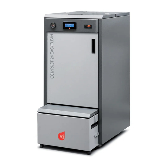
- Page 1 INSTALLATION GUIDE PELLET BOILER COMPACT 18/24 Easy Clean Instructions in English...
-
Page 2: Table Of Contents
TABLE OF CONTENTS TABLE OF CONTENTS ..................II INTRODUCTION ..................... 1 1-WARNINGS AND WARRANTY CONDITIONS ............2 2-INSTALLATION INSTRUCTIONS ..............9 3-DRAWINGS AND TECHNICAL CHARACTERISTICS ..........19 4-UNPACKING ....................22 5-POSITIONING ....................25 6-ASSEMBLY ....................26 7-TROLLEY ASSEMBLY ...................28 8-PANEL REMOVAL ..................29 9-HYDRAULIC CONNECTION ................30 10-ELECTRICAL CONNECTIONS ...............33 11-FIRST START-UP ..................34 12-MENU ENTRIES AND OPERATION ..............37... -
Page 3: Introduction
REVISIONS TO THE PUBLICATION The content of this manual is strictly technical and property of RED. No part of this manual may be translated into other languages, adapted or reproduced, even in part, in other mechanical or electronic forms, photocopies, recordings or other, without the prior written authorisation from RED. -
Page 4: 1-Warnings And Warranty Conditions
1-WARNINGS AND WARRANTY CONDITIONS SAFETY PRECAUTIONS • Installation, electrical connection, function test and maintenance must only be carried out by authorised and qualified personnel. • Install the product in accordance with all local and national legislation and regulations in force in the region or state. •... - Page 5 1-WARNINGS AND WARRANTY CONDITIONS • All liability for improper use of the product is entirely borne by the user and relieves the Manufacturer from any civil and criminal liability. • Any type of tampering or unauthorised replacement with non-original spare parts could be hazardous for the operator’s safety and relieves the company from any civil and criminal liability.
- Page 6 1-WARNINGS AND WARRANTY CONDITIONS • Do not wash the product with water. The water could get inside the unit and damage the electrical insulation and cause electric shocks. • A carbon monoxide alarm must be fitted in the room where the appliance is sited Refer too ADJ part 2.34 through too 2.36 page 41 (ONLY FOR UK).
- Page 7 1-WARNINGS AND WARRANTY CONDITIONS • IF ANY SMOKE SPILLAGE IS SEEN WITHIN THE ROOM OR THE APPLIANCE SUFFERS FROM AN EXPLOSIVE IGNITION PLEASE TURN OFF THE APPLIANCE, VENTILATE THE ROOM AND CONTACT THE INSTALLER/ SERVICE ENGINEER IMMEDIATELY. INFORMATION • In case of any problems, get in touch with your dealer, or a qualified engineer authorised by MCZ, and if a repair is necessary, insist on the use of original spare parts.
- Page 8 1-WARNINGS AND WARRANTY CONDITIONS EXCLUSIONS The guarantee does not cover malfunctions and/or damage to the appliance that arise due to the following causes: • Damage caused during transportation or relocation • all parts that develop faults due to negligence or improper use, incorrect maintenance, installation that does not comply with the manufacturer's instructions (always refer to the installation and use manual provided with the appliance) •...
- Page 9 1-WARNINGS AND WARRANTY CONDITIONS SPARE PARTS In the event of a malfunction, consult the retailer who will forward the call to the Technical Assistance Service. Use only original spare parts. The retailer or service centre can provide all necessary information regarding spare parts. We do not recommend waiting for the parts to be worn before having them replaced.
- Page 10 1-WARNINGS AND WARRANTY CONDITIONS RULES FOR INSTALLATION The product is a boiler that uses wood pellets. Below is a list of the European regulations regarding the installation of the product: EN 303-5:2012: Solid fuel boilers, with manual or automatic loading, nominal thermal power of 500 kW - Terminology, requisites, tests and marking.
-
Page 11: 2-Installation Instructions
2-INSTALLATION INSTRUCTIONS The instructions in this chapter refer explicitly to the Italian installation regulation UNI 10683. In any case, always observe the domestic regulations in force. PELLETS Wood pellets are manufactured by hot-extruding compressed sawdust which is produced during the working of natural dried wood. The compactness of the material is guaranteed by the lignin contained in the wood itself and allows pellets to be produced without glue or binders. - Page 12 2-INSTALLATION INSTRUCTIONS PRECAUTIONS REGARDING INSTALLATION IMPORTANT! Product installation and assembly must be carried out by qualified personnel. The product must be installed in a suitable place that allows easy access for it to be opened regularly and for routine maintenance to be performed.
- Page 13 2-INSTALLATION INSTRUCTIONS POSITIONING AND RESTRICTIONS In the case of simultaneous installation with other heating appliances, provide appropriate air inlets for each one (according to the instructions of each product). Installation of the product is not permitted: • in rooms where there are liquid fuel appliances with continuous or intermittent operation that draw the combustion air from the room they are installed in;...
- Page 14 2-INSTALLATION INSTRUCTIONS FOREWORD This chapter on the Smoke Flue has been produced in reference to the prescriptions of European regulations (EN13384 - EN1443 - EN1856 - EN1457). The chapter provides indications for installing an efficient and correct smoke flue but is under no circumstances to substitute the regulations in force, which the qualified technician must be in possession of.
- Page 15 2-INSTALLATION INSTRUCTIONS TECHNICAL CHARACTERISTICS Flues serving a pellet/wood fuelled appliance must meet the following requirements: • made of materials that are sufficiently resistant to mechanical stress, heat, the action of the products of combustion and their vapours. • made of materials that are impermeable to fumes, condensation, be thermally insulated and resistant to normal mechanical stress over time •...
- Page 16 2-INSTALLATION INSTRUCTIONS ROOF AT 30° A = MIN. 1.30 metres B = DISTANCE > 1.50 metres C = DISTANCE < 1.50 metres D = 0.50 metres ABOVE HIGHEST POINT E = 0.80 metres F = REFLUX ZONE 30° FIGURE 4 ROOF AT 45°...
- Page 17 2-INSTALLATION INSTRUCTIONS DIMENSIONING The drop in pressure (draft) of a flue depends on its height. Check the drop in pressure with the values indicated in the technical characteristics. The minimum height of the chimney is 3.5 meters. The interior cross-section of the flue can be circular (best variation), square or rectangular (the ratio between the interior sides must be ≤1.5) with the sides joined with a minimum radius of 20 mm.
- Page 18 2-INSTALLATION INSTRUCTIONS MAINTENANCE The flue must be kept clean, since the deposit of soot or unburned oils reduces the cross-section reducing the draft and thus compromising the efficient functioning of the heater and, if large build-ups accumulate, can catch fire. The flue and chimney must be cleaned and checked by a skilled chimney sweep at least once a year.
- Page 19 2-INSTALLATION INSTRUCTIONS CONNECTION TO FLUE The connection between the flue and the appliance must be via a smoke duct that conforms with EN 1856-2. The connecting section must extend no more than 4 m horizontally, with a maximum incline of 3% and containing a maximum of 3 90% bends (accessible for inspection - do not count the T joint at the appliance outlet).
- Page 20 2-INSTALLATION INSTRUCTIONS EXAMPLES OF CORRECT INSTALLATION 1. Installation of Ø 150 mm flue with hole for the passage of the pipe increased by: minimum 100 mm around the tube if next to non flammable parts such as cement, brick, etc.; or minimum 300 mm around the tube (or as prescribed by data tags) if next to flammable parts such as wood etc.
-
Page 21: 3-Drawings And Technical Characteristics
3-DRAWINGS AND TECHNICAL CHARACTERISTICS DRAWINGS AND CHARACTERISTICS COMPACT 18/24 EASY CLEAN DIMENSIONS (size in mm) 1038 Technical Dept. - All rights reserved - Reproduction is prohibited... - Page 22 3-DRAWINGS AND TECHNICAL CHARACTERISTICS TECHNICAL CHARACTERISTICS COMPACT 18 EASY CLEAN - 2015 COMPACT 24 EASY CLEAN Product class (EN 303-5/2012) Rated thermal capacity of the firebox 18.0 kW (15480 kcal/h) 24.5 kW (21070 kcal/h) Nominal output power: 16.8 kW (14448 kcal/h) 22.1 kW (19006 kcal/h)
- Page 23 3-DRAWINGS AND TECHNICAL CHARACTERISTICS RESIDUAL HEAD CHART 1000 1500 2000 A = RESIDUAL HEAD (mbar) B = FLOW (l/h) Technical Dept. - All rights reserved - Reproduction is prohibited...
-
Page 24: 4-Unpacking
4-UNPACKING PREPARATION AND UNPACKING The Compact Easy Clean boiler is delivered complete with all its electrical, mechanical and hydraulic components (excluding the circulator kit and thermostatic valve-OPTIONAL) and having been tested in the factory: Box 1 contains the structure of the boiler, while box 2, on top of the packaging, contains the trolley (to make it easier to move and remove ash) and the compressor, required to turn on the turbulators. - Page 25 4-UNPACKING Install the boiler in the area set aside for it, making sure it conforms to the requirements. The boiler body or unit must always be kept in a vertical position when moved, and only ever moved using suitable lifting trolleys. The packaging materials are neither toxic nor harmful, and therefore no particular disposal measures are required.
- Page 26 4-UNPACKING The end user is responsible for product storage, disposal or possible recycling in compliance with the relative applicable laws in force. Position the product and proceed with connecting it to the chimney. If the product must be connected to an exhaust pipe that goes through the rear wall (to enter the chimney), make sure not to force it in. Attention!! If the boiler smoke outlet is forced or used improperly to lift it or position it, the operation of the stove can be damaged irreparably.
-
Page 27: 5-Positioning
5-POSITIONING REQUIREMENTS FOR INSTALLATION OF THE PLANT - POSITIONING The most important thing to do before installation of the boiler is to set aside a suitable area that meets the minimum requirements for installation. • the minimum clearance in front of the product for the purpose of cleaning, maintenance, etc. must be 1000 mm; •... -
Page 28: 6-Assembly
6-ASSEMBLY Live electrical parts: only power the product after completing assembly. COMPRESSOR CONNECTION COMPRESSOR KNOCKOUT HOLE ON REAR BOILER PANEL COMPRESSOR PIPE FASTENING SCREWS (supplied) SOLENOID VALVE GASKET (supplied) POLYSTYRENE... - Page 29 6-ASSEMBLY Connect compressor “A” to the boiler as follows: • Take out compressor unit “A” from packaging 2 • Take the supplied gasket “e” and secure it to the sheet metal inside the compressor unit where it touches the boiler to avoid potential vibration (see picture on previous page) •...
-
Page 30: 7-Trolley Assembly
7-TROLLEY ASSEMBLY Take out the trolley from package 2 and proceed as follows: • move the trolley towards the boiler and make sure the feed screw goes inside the trolley's hole “P” • now lock it into place with the two side levers (see image below) Note: cap “O”... -
Page 31: 8-Panel Removal
8-PANEL REMOVAL If any work is carried out on some components of the stove or if you are just cleaning it, you need to remove the side panels. Remove the panels as follows: • remove the trolley • lift the two top covers •... -
Page 32: 9-Hydraulic Connection
9-HYDRAULIC CONNECTION PLUMBING CONNECTION IMPORTANT: The connections depend on the type of System Configuration. IMPORTANT! If installing the boiler involves another pre-existing system complete with heating equipment (gas boiler, methane boiler, fuel oil boiler, etc.), it is strongly recommended that you contact a qualified operator who subsequently will be responsible for the compliance of the system with the applicable laws in force. - Page 33 Standard UNI 8065 (water treatment of thermal plants for civil use). As standard, RED supplied the product FERNOX PROTECTOR F1 with the product. This provides long term protection against corrosion and calcium build-up for the heating appliance. It prevents the corrosion of the metal parts of the appliance, i.e.
- Page 34 A higher return temperature reduces the formation of condensation of the fumes and extends the life of the boiler. Valves available offer various calibrations. RED recommends the model (see accessories list) at 55°C with hydraulic connections of 1". Once the calibration temperature is reached, the valve opens thereby supplying hot water to the system.
-
Page 35: 10-Electrical Connections
10-ELECTRICAL CONNECTIONS GENERAL PRECAUTIONS The electrical safety of the system is guaranteed only when this is connected correctly to an efficient earthing system installed in accordance with the safety standards in force: the pipes of the gas, water and heating systems do not constitute a suitable earth system. It is necessary to ensure this essential safety requirement;... -
Page 36: 11-First Start-Up
11-FIRST START-UP BEFORE START-UP GENERAL PRECAUTIONS Remove all parts that may burn from the brazier and the product's tank (manual, various adhesive labels or any polystyrene). Make sure all the refractory materials are positioned correctly and they do not obstruct the combustion chamber. The first start-up may not be successful as the feed screw is empty and does not always manage to load the required amount of pellets in time to light the flame. - Page 37 11-FIRST START-UP The boiler will be subject to expansion and contraction during the stages of lighting and cooling down, and may therefore make slight creaking noises. This is absolutely normal as the structure is made of laminated steel and must not be considered a defect. It is extremely important to make sure the boiler does not reach high temperatures straight away, but to increase the temperature gradually using low power at first.
- Page 38 11-FIRST START-UP LOADING THE PELLETS The pellets can be loaded either manually or automatically. The tank can contain up to 150 litres or 100 kg of pellets. Manual Loading: • Open the top cover of the boiler and pour in the pellets. Automatic loading (with remote tank of 100/200 or 400 kg - optional - see accessories): •...
-
Page 39: 12-Menu Entries And Operation
12-MENU ENTRIES AND OPERATION CONTROL PANEL DISPLAY Menu options The boiler has a modern touch-screen display used to adjust individual functions in a user-friendly manner. Press the controls on the touch-screen display to launch them. We recommend: • not using protective films •... - Page 40 12-MENU ENTRIES AND OPERATION MAIN MENU Press key 6/7 (MENU) to go to the available boiler parameters. 20° 50° 10:29 MENU 70° Eco Mode on Here are the functions you can access under the MENU function: • Date and Time •...
- Page 41 12-MENU ENTRIES AND OPERATION CONFIGURATION OF PROGRAMMED MODE (TIMER) - Main menu The current time and date must be configured to ensure correct operation of the timer. There are six configurable TIMERS; for each one, the user can select a start and stop time and the days of the week when it is in use. When one or more programs are active, the status of the boiler and the TIMER "n"...
- Page 42 12-MENU ENTRIES AND OPERATION EXAMPLES OF PROGRAMMING 08:00 12:00 11:00 14:00 Boiler on between 08:00 and 14:00 08:00 11:00 11:00 14:00 Boiler on between 08:00 and 14:00 17:00 24:00 00:00 06:00 Boiler on between 17:00 on Monday to 06:00 on Tuesday NOTES ON USE OF THE TIMER •...
- Page 43 12-MENU ENTRIES AND OPERATION SETTINGS MENU The SETTINGS menu is for configuring use of the boiler. With keys 1 and 4 in the menu, select the SETTINGS control. Use key 5 to go to the settings menu and select the option you want to configure (see the list below). a.
- Page 44 12-MENU ENTRIES AND OPERATION b - Cleaning This function is only activated when the boiler is off. When it is activated, the fan turns at top speed so that the soot removed by the turbulators is sucked in. < Cleaning >...
- Page 45 12-MENU ENTRIES AND OPERATION e - External thermostat EXTERNAL THERMOSTAT (not included with the boiler, it must be provided by the user) The temperature of the boiler can also be controlled by an external thermostat in the room. It should be positioned centrally in the room where the boiler is installed.
- Page 46 12-MENU ENTRIES AND OPERATION AUTO ECO MODE The Auto-Eco mode changes the behaviour of the boiler in automatic mode, that is: when the ambient temperature set by the user is reached (the temperature is detected by the probe on the equipment or by the external thermostat), the boiler modulates at power value 1 for a short period of time;...
- Page 47 12-MENU ENTRIES AND OPERATION i - Auxiliary boiler An additional module (optional) must be installed to allow the start-up of an auxiliary boiler when the main boiler is off or has been stopped due to an alarm. By default, this function is deactivated (Off). If you need to activate it (On), go into the settings menu with key 5 and select the Auxiliary boiler option;...
- Page 48 12-MENU ENTRIES AND OPERATION < Smoke Fan rpm > < Smoke Fan rpm > Use key 5 to go to the settings menu and select the Smoke Var.rpm option. Confirm with key 5 and then with keys “b” (arrows) you can increase or reduce the %.
- Page 49 12-MENU ENTRIES AND OPERATION p - Chimney sweeper function (for maintenance operators only) This function can only be activated when the boiler is on and power is supplied, and it forces operation of the boiler at the parameters P5, with the ventilator (if present) in V5. Any corrections to the loading/smoke ventilation percentage must be read. This state lasts 20 minutes, the countdown is displayed on the panel.
- Page 50 12-MENU ENTRIES AND OPERATION The temperature in small print on the display is the value detected by the probe, while the one in large print is the set temperature (SET). The icons represent the various available SETPOINT values available. SETPOINT VALUE 1 DHW SETPOINT VALUE 70°...
- Page 51 12-MENU ENTRIES AND OPERATION q - System configuration With keys 1 and 4 in the menu, select the SETTINGS control. With key 5, go into the settings menu and select the option System Config. The display of the room temperature or external thermostat status depends on the value of the “EXT therm” parameter. CONFIGURATION 1 20°...
- Page 52 12-MENU ENTRIES AND OPERATION r - Season In configurations 2 and 3, enabling the ''summer'' function disables deviation of the 3-way valve towards the heating system to prevent the radiators from heating up, and so the flow is always towards the hot water system (DHW). Selecting the "summer"...
- Page 53 12-MENU ENTRIES AND OPERATION INFO MENU Use key 5 to go to the settings menu and select the INFO option. Use key 5 to go into the SUBMENU. < Info > Available parameters are: (Info-Product type - Fw Version - oper. hours - no. of start-ups - Feed screw load - Extractor rpm - Exchanger Voltage - Flame - Smoke T).
- Page 54 12-MENU ENTRIES AND OPERATION SYSTEM CONFIGURATIONS At the time of installation, the product must be configured according to the type of system by selecting the relative parameter in the "SETTINGS" menu. There are 5 possible configurations, described below: Configuration Description Room temperature control via boiler's on-board probe or by enabling external thermostat.
- Page 55 12-MENU ENTRIES AND OPERATION CONFIGURATION 2.1 (FACTORY SETTING) CONFIGURATION 2.2 (*) (*) DISCONNECT THE INTERNAL THREE-WAY VALVE AND FLOW SWITCH (IF PRESENT) Technical Dept. - All rights reserved - Reproduction is prohibited...
- Page 56 12-MENU ENTRIES AND OPERATION CONFIGURATION 3 (*) (*) DISCONNECT THE INTERNAL THREE-WAY VALVE AND FLOW SWITCH (IF PRESENT) CONFIGURATION 4...
- Page 57 12-MENU ENTRIES AND OPERATION CONFIGURATION 5 COMPACT HEATING DELIVERY HEATING RETURN ZONE VALVE HEATING BODIES HOT SANITARY WATER DOMESTIC COLD WATER SANITARY WATER BOILER DIVERTER VALVE BOILER THERMOSTAT THERMOSTATIC MIXER VALVE NTC PROBE 10 kΩ β3434 SANITARY WATER HEATING PUFFER HEATING SYSTEM CIRCULATOR PUFFER THERMOSTAT NTC PROBE 10 kΩ...
- Page 58 12-MENU ENTRIES AND OPERATION ASH EVACUATION SYSTEM (THE FEED SCREW IS ACTIVATED TO AUTOMATICALLY REMOVE ASH) out1 Stop Start IF IT IS ON THE SET COUNT WILL BE RUNNING, WHICH MEANS THAT THE AUTOMATIC CLEANING FUNCTION IS ACTIVATED Time value set by default is 5’ (the parameter can be changed from 5’ to 0’) WAITING TIME BETWEEN ONE CLEANING CYCLE AND THE NEXT HOURS/MINUTES Time value set by default is 1h 30’...
- Page 59 12-MENU ENTRIES AND OPERATION WIRING DIAGRAM OF THE TIMER (ASH REMOVAL SYSTEM) TROLLEY PELLET SAFETY SWITCH ASH CLEANING MOTORS POWER SUPPLY 230 V AC AUTOMATIC THERMOSTAT OPERATION OPERATING MODE The operating mode for hydro stoves is only AUTOMATIC (there is no manual operating mode available). The modulation of the flame is controlled according to the "System configuration"...
- Page 60 12-MENU ENTRIES AND OPERATION ELECTRICAL CONNECTIONS TERMINAL BLOCK CONTACTS POS.1-2 EXTERNAL THERMOSTAT/PUFFER THERMOSTAT POS.8 NEUTRAL THREE-WAY VALVE (*) POS.3-4 PUFFER/BOILER PROBE POS.9 THREE-WAY VALVE PHASE (sanitary) (*) POS.5 EARTHING POS.10 THREE-WAY VALVE PHASE (heating) (*) POS.6-7 AUXILIARY BOILER (*) DISCONNECT THE INTERNAL THREE-WAY VALVE AND FLOW SWITCH (IF PRESENT) START-UP Press key 1 (OFF) for a few seconds to start up the appliance.
-
Page 61: 13-Safety Devices And Alarms
13-SAFETY DEVICES AND ALARMS SAFETY DEVICES The product is fitted with the following safety devices PRESSURE SWITCH Monitors pressure in the smoke duct. It is designed to shut down the pellet feed screw in the event of an obstructed flue or significant back-pressure. - Page 62 13-SAFETY DEVICES AND ALARMS ALARM SIGNALLING A01 = alarm code No Ignition No ignition = alarm description 10/01/2014 22:30 10/01/2014 22:30 = time and date of the alarm Clean Burner and Try Again Clean the brazier and fill up the tank = description of the solution to clear MENU Reset the alarm...
- Page 63 13-SAFETY DEVICES AND ALARMS ALARM RESET NEVER open the appliance door whilst the stove is either in the initial startup or on its shut down cycle, pellets will still be smoldering or therefore volatiles may be present. ATTENTION! If during operation or initial ignition you encounter smoke spillage in to the room from the appliance or the flue then please switch off the appliance, ventilate the room and contact the installation / service engineer immediately.
-
Page 64: 14-Recommendations For A Safe Use
14-RECOMMENDATIONS FOR A SAFE USE ONLY CORRECT INSTALLATION AND APPROPRIATE MAINTENANCE AND CLEANING OF THE APPLIANCE CAN GUARANTEE CORRECT OPERATION AND SAFE USE OF THE PRODUCT We would like to inform you that we are aware of cases of malfunctioning of domestic pellet-fuelled heating products, mainly due to incorrect installation and use, as well as inadequate maintenance. -
Page 65: 15-Cleaning And Maintenance
15-CLEANING AND MAINTENANCE Disconnect the product from the 230V power supply before performing any maintenance operation. DAILY OR WEEKLY CLEANING PERFORMED BY THE USER If the pellets in the tank run out, unburned pellets may accumulate in the brazier; always remove these residues from the brazier. Check the status of your brazier every 15 days. - Page 66 15-CLEANING AND MAINTENANCE CLEANING THE TROLLEY Red recommends checking the level of the ash inside the trolley every 15 days with the boiler switched off and in any case empty the container every two months(*). Carry out this check as follows: •...
- Page 67 15-CLEANING AND MAINTENANCE PERIODIC CLEANING PERFORMED BY A QUALIFIED TECHNICIAN Cleaning pipes When the boiler is cold, lift the exchanger cover and the tank cover and remove the side panels (see the indications in the dedicated paragraph). Unlock the fastening system of the turbulators as follows: •...
- Page 68 15-CLEANING AND MAINTENANCE Remove the two turbulators “T” and, using a stiff rod or a bottle brush, clean the internal pipe unit and the turbulators; remove all of the accumulated ash, use a vacuum cleaner if necessary. Check the cover seal and replace it if necessary.
- Page 69 15-CLEANING AND MAINTENANCE Cleaning the bottom ash drawers When the trolley is taken out to check the level of the ash and, in any case, when the turbulators are cleaned, you need to also clean the lower drawers “T” and “K”. CLEANING THE SMOKE EXHAUST SYSTEM AND GENERAL CHECKS Clean the smoke extractor system, especially around the “T”...
- Page 70 15-CLEANING AND MAINTENANCE PERIODICAL CHECK OF THE DOOR CLOSURE Make sure the door closure ensures a correct sealing action (with the “paper sheet” test) and that when the door is closed, the closing block (X in the figure) does not protrude from the sheet metal to which it is secured. For some products it will be necessary to disassemble the cladding to be able to assess the anomalous protrusion of the block when the door is closed.
- Page 71 15-CLEANING AND MAINTENANCE CHECKING THE INTERNAL COMPONENTS ATTENTION! The internal electromechanical components must only be checked by qualified personnel whose technical expertise includes combustion and electricity. We recommend that an annual maintenance service is carried out with a scheduled service contract. This service is essentially a visual and functional inspection of the following components: PARTS/INTERVAL 15 DAYS*...
-
Page 72: 16-Faults/Causes/Solutions
16-FAULTS/CAUSES/SOLUTIONS CHECKING THE INTERNAL COMPONENTS ATTENTION: GUIDE FOR THE USE OF THE SPECIALISED TECHNICIAN ONLY ATTENTION: All repairs must be carried out exclusively by a specialised technician, while the boiler is completely cold and the electric plug is disconnected. The operations in bold type must be carried out by specialised personnel. The manufacturer will not be liable and the guarantee is invalidated if this condition is not respected. - Page 73 16-FAULTS/CAUSES/SOLUTIONS ANOMALY POSSIBLE CAUSES SOLUTIONS The boiler runs for a few minutes and Start-up phase is not completed Repeat start-up then goes out. Temporary power cut Wait for the automatic restart Clogged smoke duct Clean the smoke duct Faulty or malfunctioning temperature Check and replace the probes probes Faulty spark plug...
- Page 74 16-FAULTS/CAUSES/SOLUTIONS The stove does not run No power supply Check that the plug is inserted and the main switch is in the “I” position. Pellet probe stop Cancel stoppage by changing the setting of the rear thermostat. If the problem persists, request assistance.
-
Page 75: 17-Wiring Diagram
17-WIRING DIAGRAM MOTHERBOARD WIRING KEY FUSE 14. EXTERNAL THERMOSTAT CONNECTION (TERMINAL) BOARD PHASE 15. ROOM TEMPERATURE PROBE BOARD NEUTRAL 16. PUFFER/BOILER PROBE CONNECTION (TERMINAL) SMOKE EXTRACTOR FAN 17. BOILER WATER TEMPERATURE PROBE ROOM FAN 18. SMOKE EXTRACTOR FAN REVOLUTION CONTROL PELLET SAFETY THERMOSTAT 19. - Page 76 Via La Croce n°8 33074 Vigonovo di Fontanafredda (PN) – ITALY Telephone: +39 0434/599599 r.a. Fax: +39 0434/599598 Internet: www.mcz.it e-mail: info.red@mcz.it REV. 4 26/01/2016 8901421600...
Need help?
Do you have a question about the COMPACT 18 and is the answer not in the manual?
Questions and answers