Table of Contents
Advertisement
Advertisement
Table of Contents

Related Manuals for RED COMPACT 14-2015


Summary of Contents for RED COMPACT 14-2015
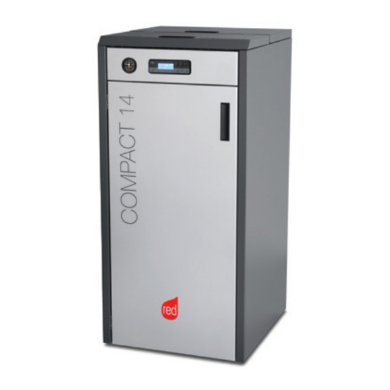
- Page 1 INSTALLATION GUIDE PELLET BOILER COMPACT 14-2015 Instructions in English...
-
Page 2: Table Of Contents
TABLE OF CONTENTS TABLE OF CONTENTS ..................II INTRODUCTION ..................... 1 1-WARNINGS AND WARRANTY CONDITIONS ............2 2-INSTALLATION INSTRUCTIONS ..............9 3-DRAWINGS AND TECHNICAL CHARACTERISTICS ..........19 4 - UNPACKING ....................22 5 - POSITIONING ..................24 6 - INSTALLATION AND DISASSEMBLY .............25 7 - PUMP KIT AND HYDRAULIC CONNECTION ............30 8 - ELECTRICAL CONNECTION .................35 9 - FIRST START-UP ..................37... -
Page 3: Introduction
INTRODUCTION Dear Customer, Our boilers are designed and built in compliance with the European standard EN 303-5 (manual or automatic loading solid fuel boilers). They also meet the essential requirements of directive 2006/95/EC (Low Voltage) and directive 2004/108/EC (Electromagnetic Compatibility). To get the best performance out of your boiler, we suggest you read the instructions in this manual carefully before starting it up for the first time. -
Page 4: 1-Warnings And Warranty Conditions
1-WARNINGS AND WARRANTY CONDITIONS SAFETY PRECAUTIONS • Installation, electrical connection, function test and maintenance must only be carried out by authorised and qualified personnel. • Install the product in accordance with all local and national legislation and regulations in force in the region or state. •... - Page 5 1-WARNINGS AND WARRANTY CONDITIONS • Any type of tampering or unauthorised replacement with non-original spare parts could be hazardous for the operator’s safety and relieves the company from any civil and criminal liability. • Many of the surfaces of the product get very hot (door, handle, glass, smoke extraction pipes, etc.).
- Page 6 1-WARNINGS AND WARRANTY CONDITIONS • A carbon monoxide alarm must be fitted in the room where the appliance is sited Refer too ADJ part 2.34 through too 2.36 page 41 (ONLY FOR UK). • If there is a fire in the flue pipe, extinguish the stove, disconnect it from the power supply and never open the door.
- Page 7 1-WARNINGS AND WARRANTY CONDITIONS INFORMATION • In case of any problems, get in touch with your dealer, or a qualified engineer authorised by MCZ, and if a repair is necessary, insist on the use of original spare parts. • Use only the fuel recommended by MCZ (for Italy pellets with a diameter of 6 mm and for other European countries with a diameter of 6-8 mm) and provided only with an automatic supply system.
- Page 8 1-WARNINGS AND WARRANTY CONDITIONS EXCLUSIONS The guarantee does not cover malfunctions and/or damage to the appliance that arise due to the following causes: • Damage caused during transportation or relocation • all parts that develop faults due to negligence or improper use, incorrect maintenance, installation that does not comply with the manufacturer's instructions (always refer to the installation and use manual provided with the appliance) •...
- Page 9 1-WARNINGS AND WARRANTY CONDITIONS SPARE PARTS In the event of a malfunction, consult the retailer who will forward the call to the Technical Assistance Service. Use only original spare parts. The retailer or service centre can provide all necessary information regarding spare parts. We do not recommend waiting for the parts to be worn before having them replaced.
- Page 10 1-WARNINGS AND WARRANTY CONDITIONS RULES FOR INSTALLATION The product is a boiler that uses wood pellets. Below are some reference European standards for product installation: EN 303-5:2012: Solid fuel boilers, with manual or automatic loading, nominal thermal power of 500 kW - Terminology, requisites, tests and marking.
-
Page 11: 2-Installation Instructions
2-INSTALLATION INSTRUCTIONS The instructions in this chapter refer explicitly to the Italian installation regulation UNI 10683. In any case, always observe the domestic regulations in force. PELLETS Wood pellets are manufactured by hot-extruding compressed sawdust which is produced during the working of natural dried wood. The compactness of the material is guaranteed by the lignin contained in the wood itself and allows pellets to be produced without glue or binders. - Page 12 2-INSTALLATION INSTRUCTIONS PRECAUTIONS REGARDING INSTALLATION IMPORTANT! Product installation and assembly must be carried out by qualified personnel. The product must be installed in a suitable place that allows easy access for it to be opened regularly and for routine maintenance to be performed.
- Page 13 2-INSTALLATION INSTRUCTIONS POSITIONING AND RESTRICTIONS In the case of simultaneous installation with other heating appliances, provide appropriate air inlets for each one (according to the instructions of each product). Installation of the product is not permitted: • in rooms where there are liquid fuel appliances with continuous or intermittent operation that draw the combustion air from the room they are installed in;...
- Page 14 2-INSTALLATION INSTRUCTIONS FOREWORD This chapter on the Smoke Flue has been produced in reference to the prescriptions of European regulations (EN13384 - EN1443 - EN1856 - EN1457). The chapter provides indications for installing an efficient and correct smoke flue but is under no circumstances to substitute the regulations in force, which the qualified technician must be in possession of.
- Page 15 2-INSTALLATION INSTRUCTIONS TECHNICAL CHARACTERISTICS Flues serving a pellet/wood fuelled appliance must meet the following requirements: • made of materials that are sufficiently resistant to mechanical stress, heat, the action of the products of combustion and their vapours. • made of materials that are impermeable to fumes, condensation, be thermally insulated and resistant to normal mechanical stress over time •...
- Page 16 2-INSTALLATION INSTRUCTIONS ROOF AT 30° A = MIN. 1.30 metres B = DISTANCE > 1.50 metres C = DISTANCE < 1.50 metres D = 0.50 metres ABOVE HIGHEST POINT E = 0.80 metres F = REFLUX ZONE 30° FIGURE 4 ROOF AT 60°...
- Page 17 2-INSTALLATION INSTRUCTIONS DIMENSIONING The drop in pressure (draft) of a flue depends on its height. Check the drop in pressure with the values indicated in the technical characteristics. The minimum height of the chimney is 3.5 meters. The interior cross-section of the flue can be circular (best variation), square or rectangular (the ratio between the interior sides must be ≤1.5) with the sides joined with a minimum radius of 20 mm.
- Page 18 2-INSTALLATION INSTRUCTIONS MAINTENANCE The flue must be kept clean, since the deposit of soot or unburned oils reduces the cross-section reducing the draft and thus compromising the efficient functioning of the heater and, if large build-ups accumulate, can catch fire. The flue and chimney must be cleaned and checked by a qualified chimney sweep at least once a year.
- Page 19 2-INSTALLATION INSTRUCTIONS CONNECTION TO FLUE The connection between the flue and the appliance must be via a smoke duct that conforms with EN 1856-2. The connecting section must extend no more than 4 m horizontally, with a maximum incline of 3% and containing a maximum of 3 90% bends (accessible for inspection - do not count the T joint at the appliance outlet).
- Page 20 2-INSTALLATION INSTRUCTIONS EXAMPLES OF CORRECT INSTALLATION 1. Installation of Ø150mm flue with hole for the passage of the pipe increased by: minimum 100 mm around the tube if next to non flammable parts such as cement, brick, etc.; or minimum 300 mm around the tube (or as prescribed by data tags) if next to flammable parts such as wood etc.
-
Page 21: 3-Drawings And Technical Characteristics
3-DRAWINGS AND TECHNICAL CHARACTERISTICS DRAWINGS AND CHARACTERISTICS COMPACT 14 DIMENSIONS (dimensions in mm) R=50 Technical Dept. - All rights reserved - Reproduction is prohibited... - Page 22 3-DRAWINGS AND TECHNICAL CHARACTERISTICS TECHNICAL CHARACTERISTICS COMPACT 14 Product class (EN 303-5/2012) Rated thermal capacity of the firebox 13.6 kW (11696 kcal/h) Nominal output power: 12.3 kW (10578 kcal/h) Minimum output power 3.3 kW (2838 kcal/h) Efficiency at Max 90.6% Efficiency at Min 91.5% Temperature of exhaust smoke at Max...
- Page 23 3-DRAWINGS AND TECHNICAL CHARACTERISTICS Residual head 1000 1500 2000 A = Residual head (mbar) B = Flow (l/h) Technical Dept. - All rights reserved - Reproduction is prohibited...
-
Page 24: Unpacking
4 - UNPACKING PREPARATION AND UNPACKING The Compact 14 boiler is delivered complete with all its electrical, mechanical and hydraulic components (excluding the pump kit- OPTIONAL) and having been tested in the factory: Remove the cardboard, remove the brackets that secure the boiler to the pallet as well as the polystyrene. To remove the rear bracket (fig.2) one must remove the three screws “x”... - Page 25 4 - UNPACKING To remove the front bracket (fig.3) proceed as follows: • open the door • remove screw “s” • remove screw “t” • lift and remove bracket “A” Figure 3 - Front bracket removal Install the boiler in the area set aside for it, making sure it conforms to the requirements. The boiler body or unit must always be kept in a vertical position when moved, and only ever moved using suitable lifting trolleys.
-
Page 26: Positioning
5 - POSITIONING REQUIREMENTS FOR INSTALLATION OF THE PLANT - POSITIONING The most important thing to do before installation of the boiler is to set aside a suitable area that meets the minimum requirements for installation. • the minimum clearance in front of the product to allow suitable access for cleaning, maintenance, etc. must be 700 mm; the minimum permissible distance between the back of the product and a wall must be 400 mm;... -
Page 27: Installation And Disassembly
6 - INSTALLATION AND DISASSEMBLY FUMES EXHAUST AND COMBUSTION AIR INLET The boiler is fitted at the back with a pipe “U” 0100 mm for fumes exhaust and with a pipe “E” 0 50 mm for combustion air inlet. Technical Dept. - All rights reserved - Reproduction is prohibited... - Page 28 5 - POSITIONING FOOT ADJUSTMENT The underside of the boiler is fitted with adjustable feet. Use a spanner to unscrew the feet to adjust the length and make the structure stable. TURN THE FEET CLOCKWISE TO RAISE THE PRODUCT. TURN THE FEET ANTI-CLOCKWISE TO LOWER THE PRODUCT. OPENING/CLOSING THE FIREBOX DOOR ATTENTION! The door must be securely closed for the boiler to work correctly.
- Page 29 5 - POSITIONING ACCESS TO THE ELECTRONIC BOARD To access the electronic board one must remove the two screws “N” and remove the door “M”. Technical Dept. - All rights reserved - Reproduction is prohibited...
- Page 30 5 - POSITIONING REAR PANEL REMOVAL To install the pump kit or for interventions on the boiler components one may need to remove the rear panel “O”. To do this one must remove the 4 screws “P” and remove the panel “O”.
- Page 31 5 - POSITIONING SIDE PANEL REMOVAL Also with regard to the right side panel, one may need to remove it to in order to work on the boiler. To do this one must: • Lift the two covers “A” and “B” •...
-
Page 32: Pump Kit And Hydraulic Connection
7 - PUMP KIT AND HYDRAULIC CONNECTION PUMP KIT (Optional) The boilers must be connected to an OPTIONAL hydraulic kit (see accessories listing). There are two types of hydraulic kits available for heating: pump (FIG.4) and high efficiency pump (FIG.5). FIG.4 - PUMP KIT FIG.5 - HIGH EFFICIENCY PUMP KIT For the installation instructions of the various kits refer to the manual contained in the kit itself. - Page 33 7 - PUMP KIT AND HYDRAULIC CONNECTION By way of example, in the figure below, the installation of the pump kit for high efficiency heating. The pipe “M” must be connected to the boiler delivery pipe, while the hose “T” from the expansion vessel (already connected as standard to the boiler) must be connected to the kit as well as the pipe “R”...
- Page 34 Standard UNI 8065 (water treatment of thermal plants for civil use). As standard, RED supplied the product FERNOX PROTECTOR F1 with the product. This provides long term protection against corrosion and calcium build-up for the heating appliance. It prevents the corrosion of the metal parts of the appliance, i.e.
- Page 35 7 - PUMP KIT AND HYDRAULIC CONNECTION • after starting up the boiler for the first time and bringing the system up to temperature, stop the pumps and repeat the air purging procedure; • leave the system to cool, and if necessary, restore the water pressure to 1 bar. NOTE In systems with a closed vessel, where possible, the water pressure in the heating system must not be lower than 1 bar when the system is at room temperature;...
- Page 36 A higher return temperature reduces the formation of condensation of the fumes and extends the life of the boiler. Valves available offer various calibrations. RED recommends the model (see accessories list) at 55°C with hydraulic connections of 1". Once the calibration temperature is reached, the valve opens allowing water to flow and supplying hot water to the system.
-
Page 37: Electrical Connection
8 - ELECTRICAL CONNECTION GENERAL PRECAUTIONS The electrical safety of the system is guaranteed only when this is connected correctly to an efficient earthing system installed in accordance with the safety standards in force: the pipes of the gas, water and heating systems do not constitute a suitable earth system. It is necessary to ensure this essential safety requirement;... - Page 38 8 - ELECTRICAL CONNECTION ELECTRICAL CONNECTION First connect the power cable at the back of the boiler and then to a wall socket The main switch at the back must only be operated for turning the boiler on and off.
-
Page 39: First Start-Up
9 - FIRST START-UP GENERAL PRECAUTIONS Remove any objects that may burn from the brazier (manual, various adhesive labels or any remaining polystyrene). Check that the brazier is positioned correctly and rests properly on the base. The first start-up may not be successful as the feed screw is empty and does not always manage to load the required amount of pellets in time to light the flame. - Page 40 9 - FIRST START-UP Do not stand close to the stove and, as mentioned, air the room. The smoke and smell of paint will disappear after about an hour of operation, however, they are not harmful in any case. The boiler will be subject to expansion and contraction during the lighting and cooling down stages, and may therefore make slight creaking noises.
- Page 41 9 - FIRST START-UP LOADING THE PELLETS The pellets can be loaded either manually or automatically. The tank can contain up to 35 litres or 25 kg of pellets. Manual Loading: • Open the top cover of the boiler and pour in the pellets. Never remove the protective grate from inside the tank.
- Page 42 9 - FIRST START-UP SAFETY PROCEDURE TO FOLLOW IF ANY SMOKE SPILLAGE IS SEEN WITHIN THE ROOM OR THE APPLIANCE SUFFERS FROM AN EXPLOSIVE IGNITION PLEASE TURN OFF THE APPLIANCE, VENTILATE THE ROOM AND CONTACT THE INSTALLER/ SERVICE ENGINEER IMIDIAT- LEY.
-
Page 43: Menu Items And Function
10 - MENU ITEMS AND FUNCTION CONTROL PANEL DISPLAY Menu options 1. Switching on/switching off the boiler 5. Decrease set temperature / programming functions. 2. Scrolling down through the programming menu 6. Increase set temperature / programming functions. 3. Menu 7. - Page 44 10 - MENU ITEMS AND FUNCTION PROGRAMMED MODE (TIMER) - Main menu The current time and date must be configured to ensure correct operation of the timer. There are six configurable TIMERS; for each one, the user can select a start and stop time and the days of the week when it is in use. When one or more programs are active, the status of the boiler and the TIMER "n"...
- Page 45 10 - MENU ITEMS AND FUNCTION NOTES ON USE OF THE TIMER • The timer always starts the boiler with the last temperature and ventilation settings (or with the default settings at 20°C and V3 if they have never been altered). •...
- Page 46 10 - MENU ITEMS AND FUNCTION SETTINGS MENU The SETTINGS menu is for configuring use of the boiler: a. Language. b. Cleaning (shown only when boiler is off). Auger loading (shown only when boiler is off). d. Tones. e. External thermostat (activation). Auto Eco (activation).
- Page 47 10 - MENU ITEMS AND FUNCTION c - Load auger This is for filling the the pellet loading system. This can be enabled only when the boiler is off. A countdown appears. The auger stops automatically at the end of the countdown and the menu closes. To select ''Load auger'' (only with boiler off) proceed as follows: •...
- Page 48 10 - MENU ITEMS AND FUNCTION g - Eco Switch-off T To select the Eco Stop T function, proceed as follows: • Press the "menu" key. • Use the arrow keys to scroll through and select "Settings" • Press “menu” to confirm. •...
- Page 49 10 - MENU ITEMS AND FUNCTION i - Auxiliary boiler An additional module (optional) must be installed to allow the start-up of an auxiliary boiler when the main boiler is off or has been stopped due to an alarm. The default settings have this function disabled. To enable the function, go to the settings menu. l - Pellet Recipe This function is for adapting the boiler to the type of pellet in use.
- Page 50 10 - MENU ITEMS AND FUNCTION l - Maximum power Allows you to set the maximum power limit of the flames which the boiler can use to reach the set target temperature. Modify the power as follows: • Press the "menu" key. •...
- Page 51 10 - MENU ITEMS AND FUNCTION o - System configuration To change the configuration of the system, proceed as follows: • Press the "menu" key. • Use the arrow keys to scroll through and select "Settings" • Press 3 “menu” to confirm. •...
- Page 52 10 - MENU ITEMS AND FUNCTION SYSTEM CONFIGURATIONS At the time of installation, the product must be configured according to the type of system by selecting the relative parameter in the "SETTINGS" menu. There are 5 possible configurations, described below: Configuration Description Room temperature control via boiler's on-board probe or by enabling external thermostat FACTORY SETTING...
- Page 53 10 - MENU ITEMS AND FUNCTION CONFIGURATION 2 CONFIGURATION 3 Technical Dept. - All rights reserved - Reproduction is prohibited...
- Page 54 10 - MENU ITEMS AND FUNCTION CONFIGURATION 4...
- Page 55 10 - MENU ITEMS AND FUNCTION CONFIGURATION 5 COMPACT 14 HEATING DELIVERY HEATING RETURN ZONE VALVE HEATING BODIES HOT SANITARY WATER DOMESTIC COLD WATER SANITARY WATER BOILER DIVERTER VALVE BOILER THERMOSTAT THERMOSTATIC MIXER VALVE NTC PROBE 10 kΩ β3434 SANITARY WATER HEATING PUFFER HEATING SYSTEM CIRCULATOR PUFFER THERMOSTAT...
- Page 56 10 - MENU ITEMS AND FUNCTION OPERATING MODE The operating mode for boilers is always AUTOMATIC (there is no manual operating mode available). The modulation of the flame is controlled according to the "System configuration" by the room temperature probe located at the back of the appliance (see pos.S), by the external thermostat, by the temperature of the water in the boiler or by the NTC probes.
- Page 57 10 - MENU ITEMS AND FUNCTION START-UP Press key 1 (esc) to start up the appliance. The display will show ON with the flashing flame symbol. When the flame stops blinking, the boiler has reached the operating condition for "supplying power". The default target room temperature is set at 20°C.
-
Page 58: Safety Devices And Alarms
11 - SAFETY DEVICES AND ALARMS SAFETY DEVICES The product is fitted with the following safety devices PRESSURE SWITCH Monitors pressure in the smoke duct. It is designed to shut down the pellet feed screw in the event of an obstructed flue or significant back-pressure. - Page 59 11 - SAFETY DEVICES AND ALARMS IT IS FORBIDDEN TO TAMPER WITH THE SAFETY DEVICES If the product is NOT used as described in this instruction manual, the manufacturer declines all liability for any damage caused to persons and property. In particular: •...
- Page 60 11 - SAFETY DEVICES AND ALARMS ALARM SIGNALLING When a condition occurs other than the one expected for regular operation of the boiler, an alarm is triggered. The reason for the alarm is given on the control panel. The sound signal is not enabled for alarms A01-A02 in order not to disturb the user when there is an absence of pellets in the night tank.
- Page 61 11 - SAFETY DEVICES AND ALARMS To reset the alarm, press and hold key 1 (ESC) for a few seconds. The boiler checks whether the cause of the alarm is ongoing. In the first case, the alarm continues to be displayed, in the second case it turns OFF. If the alarm persists, contact a service centre.
-
Page 62: 12-Recommendations For A Safe Use
12-RECOMMENDATIONS FOR A SAFE USE ONLY CORRECT INSTALLATION AND APPROPRIATE MAINTENANCE AND CLEANING OF THE APPLIANCE CAN GUARANTEE CORRECT OPERATION AND SAFE USE OF THE PRODUCT We would like to inform you that we are aware of cases of malfunctioning of domestic pellet-fuelled heating products, mainly due to incorrect installation and use, as well as inadequate maintenance. -
Page 63: Maintenance And Cleaning
13 - MAINTENANCE AND CLEANING DAILY OR WEEKLY CLEANING PERFORMED BY THE USER Only a proper maintainance and cleaning of the product can assure you the correct functionality and a safe use of your stove. ATTENTION! All the cleaning operations of all parts must be performed with the product completely cold and the plug disconnected. - Page 64 13 - MAINTENANCE AND CLEANING CLEAN THE EXCHANGER AND THE COMPARTMENT BENEATH THE BRAZIER EVERY 2/3 DAYS Cleaning the exchanger and the compartment beneath the brazier is a simple operation but very important if the boiler is to maintain optimal performance. We therefore recommend cleaning the internal exchanger every 2-3 days, performing these simple operations in sequence: •...
- Page 65 13 - MAINTENANCE AND CLEANING PERIODIC CLEANING PERFORMED BY A QUALIFIED TECHNICIAN CLEANING THE EXCHANGER AND PIPE UNIT CLEANING THE UPPER COMPARTMENT When the boiler has cooled down lift the front cover; undo the two screws “I” on the cover “H”. Remove the two screws “L” and remove the cover “H”.
- Page 66 13 - MAINTENANCE AND CLEANING CLEANING THE LOWER COMPARTMENT Open the door of the burner “A” and pull out the brazier “B”; extract the ash drawer “C” and empty it. Remove the three screws “F” and remove the cap “E”. If needed replace the gasket “D”. Clean the brazier, ash drawer and compartment under cap “E”, vacuum any built-up ash and soot.
- Page 67 13 - MAINTENANCE AND CLEANING CLEANING OF SMOKE DUCT AND GENERAL CHECKS: Clean the smoke extractor duct, especially around the T joints, bends and any horizontal sections. For information on cleaning the flue, contact a chimney sweep. Check the integrity of the ceramic fibre seals on the door of the boiler. If necessary, order new replacement seals from the retailer or contact an authorized service centre to carry out this task.
- Page 68 13 - MAINTENANCE AND CLEANING REPLACEMENT OF OVERPRESSURE SILICON DAMPER FOR COMBUSTION CHAMBER The overpressures sillicon damper “G” for combustion chamber (fig. A) shall be replaced with a new one yearly (during the periodical maintainance) in order to keep the overpressure safety system efficient. For replacement use the following instructions •...
- Page 69 13 - MAINTENANCE AND CLEANING EVERY EVERY PARTS/INTERVAL 2-3 DAYS EVERY WEEK 15 DAYS 60-90 DAYS SEASON SEASONS Cleaning the brazier * Cleaning the ash collection tray with the vacuum cleaner Cleaning the ash tray Cleaning the fire door porthole Cleaning pipes Ash drawer lower compartment cleaning...
-
Page 70: Troubleshooting
14 - TROUBLESHOOTING CHECKING THE INTERNAL COMPONENTS ATTENTION: GUIDE FOR THE USE OF THE SPECIALISED TECHNICIAN ONLY ATTENTION: All repairs must be carried out exclusively by a specialised technician, while the boiler is completely cold and the electric plug is disconnected. The operations in bold type must be carried out by specialised personnel. The manufacturer will not be liable and the guarantee is invalidated if this condition is not respected. - Page 71 14 - TROUBLESHOOTING ANOMALY POSSIBLE CAUSES SOLUTIONS The boiler runs for a few minutes and Start-up phase is not completed Repeat start-up then goes out. Temporary power cut Wait for the automatic restart Clogged smoke duct Clean the smoke duct Faulty or malfunctioning temperature Check and replace the probes probes...
- Page 72 14 - TROUBLESHOOTING The stove does not run No power supply Check that the plug is inserted and the main switch is in the “I” position. Pellet probe stop Cancel stoppage by changing the setting of the rear thermostat. If the problem persists, request assistance.
-
Page 73: Electrical Plan
15 - ELECTRICAL PLAN MOTHERBOARD WIRING KEY FUSE 14. EXTERNAL THERMOSTAT CONNECTION (TERMINAL) BOARD PHASE 15. ROOM TEMPERATURE PROBE BOARD NEUTRAL 16. PUFFER/BOILER PROBE CONNECTION (TERMINAL) SMOKE EXTRACTOR FAN 17. BOILER WATER TEMPERATURE PROBE ROOM FAN 18. SMOKE EXTRACTOR FAN REVOLUTION CONTROL PELLET SAFETY THERMOSTAT 19. - Page 76 Via La Croce n°8 33074 Vigonovo di Fontanafredda (PN) – ITALY Telephone: +39 0434/599599 r.a. Fax: +39 0434/599598 Internet: www.mcz.it e-mail: info.red@mcz.it 8901504400 REV. 1 03/02/2016...
Need help?
Do you have a question about the COMPACT 14-2015 and is the answer not in the manual?
Questions and answers