
Related Manuals for RED LOGIKA 25


Summary of Contents for RED LOGIKA 25
- Page 1 INSTALLATION GUIDE PELLET BOILER LOGIKA 25-35 LOGIKA 25-35 REFILL PART 1 - ASSEMBLY Translation of the original instructions...
-
Page 2: Table Of Contents
TABLE OF CONTENTS TABLE OF CONTENTS ..................II INTRODUCTION ..................... 1 1-WARNINGS AND WARRANTY CONDITIONS ............2 2-INSTALLATION INSTRUCTIONS ..............7 3-DRAWINGS AND TECHNICAL CHARACTERISTICS ..........18 4 - UNPACKING ....................22 5 - POSITIONING ..................26 6 - INSTALLATION AND ASSEMBLY OF BOILER ...........28 7 - INSTALLATION AND ASSEMBLY OF TANK ............49 8 - ASSEMBLY OF BOILER AESTHETICS UNIT .............60 9 - ASSEMBLY OF TROLLEY ................65... -
Page 3: Introduction
INTRODUCTION Dear Customer, Our boilers are designed and built in compliance with the European standard EN 303-5 (manual or automatic loading solid fuel boilers). They also meet the essential requirements of directive 2006/95/EC (Low Voltage) and directive 2004/108/EC (Electromagnetic Compatibility). To get the best performance out of your boiler, we suggest you read the instructions in this manual carefully before starting it up for the first time. -
Page 4: 1-Warnings And Warranty Conditions
1-WARNINGS AND WARRANTY CONDITIONS SAFETY PRECAUTIONS • Installation, electrical connection, function test and maintenance must only be carried out by authorised and qualified personnel. • Install the product in accordance with all local and national legislation and regulations in force in the region or state. • Only use the fuel recommended by the manufacturer. - Page 5 1-WARNINGS AND WARRANTY CONDITIONS INFORMATION: Please contact the retailer or qualified personnel authorised by the company to resolve a problem. • You must only use the fuel specified by the manufacturer. • Check and clean the smoke extraction pipes regularly (connection to the chimney). • Always keep the cover of the fuel hopper closed.
- Page 6 1-WARNINGS AND WARRANTY CONDITIONS EXCLUSIONS The guarantee does not cover malfunctions and/or damage to the appliance that arise due to the following causes: • Damage caused during transportation or relocation • all parts that develop faults due to negligence or improper use, incorrect maintenance, installation that does not comply with the manufacturer’s instructions (always refer to the installation and use manual provided with the appliance) •...
- Page 7 1-WARNINGS AND WARRANTY CONDITIONS SPARE PARTS In the event of a malfunction, consult the retailer who will forward the call to the Technical Assistance Service. Use only original spare parts. The retailer or service centre can provide all necessary information regarding spare parts. We do not recommend waiting for the parts to be worn before having them replaced.
- Page 8 1-WARNINGS AND WARRANTY CONDITIONS RULES FOR INSTALLATION The product is a boiler that uses wood pellets. Below is a list of European regulations regarding the installation of the product: EN 303-5:2012: Solid fuel boilers, with manual or automatic loading, nominal thermal power of 500 kW - Terminology, requisites, tests and marking.
-
Page 9: 2-Installation Instructions
2-INSTALLATION INSTRUCTIONS The instructions in this chapter refer explicitly to the Italian installation regulation UNI 10683. In any case, always observe the domestic regulations in force. PELLETS Wood pellets are manufactured by hot-extruding compressed sawdust which is produced during the working of natural dried wood. The compactness of the material is guaranteed by the lignin contained in the wood itself and allows pellets to be produced without glue or binders. - Page 10 2-INSTALLATION INSTRUCTIONS PRECAUTIONS REGARDING INSTALLATION IMPORTANT! Product installation and assembly must be carried out by qualified personnel. The product must be installed in a suitable place that allows easy access for it to be opened regularly and for routine maintenance to be performed.
- Page 11 2-INSTALLATION INSTRUCTIONS POSITIONING AND RESTRICTIONS In the case of simultaneous installation with other heating appliances, provide appropriate air inlets for each one (according to the instructions of each product). Installation of the product is not permitted: • in rooms where there are liquid fuel appliances with continuous or intermittent operation that draw the combustion air from the room they are installed in;...
- Page 12 2-INSTALLATION INSTRUCTIONS FOREWORD This chapter on the Smoke Flue has been produced in reference to the prescriptions of European regulations (EN13384 - EN1443 - EN1856 - EN1457). The chapter provides indications for installing an efficient and correct smoke flue but is under no circumstances to substitute the regulations in force, which the qualified technician must be in possession of.
- Page 13 2-INSTALLATION INSTRUCTIONS TECHNICAL CHARACTERISTICS Flues serving a pellet/wood fuelled appliance must meet the following requirements: • made of materials that are sufficiently resistant to mechanical stress, heat, the action of the products of combustion and their vapours. • made of materials that are impermeable to fumes, condensation, be thermally insulated and resistant to normal mechanical stress over time •...
- Page 14 2-INSTALLATION INSTRUCTIONS ROOF AT 30° A = MIN. 1.30 metres B = DISTANCE > 1.50 metres C = DISTANCE < 1.50 metres D = 0.50 metres ABOVE HIGHEST POINT E = 0.80 metres F = REFLUX ZONE 30° FIGURE 4 ROOF AT 60°...
- Page 15 2-INSTALLATION INSTRUCTIONS DIMENSIONING The drop in pressure (draft) of a flue depends on its height. Check the drop in pressure with the values indicated in the technical characteristics. The minimum height of the chimney is 3.5 meters. The interior cross-section of the flue can be circular (best variation), square or rectangular (the ratio between the interior sides must be ≤1.5) with the sides joined with a minimum radius of 20 mm.
- Page 16 2-INSTALLATION INSTRUCTIONS MAINTENANCE The flue must be kept clean, since the deposit of soot or unburned oils reduces the cross-section reducing the draft and thus compromising the efficient functioning of the heater and, if large build-ups accumulate, can catch fire. The flue and chimney must be cleaned and checked by a qualified chimney sweep at least once a year.
- Page 17 2-INSTALLATION INSTRUCTIONS CONNECTION TO FLUE The connection between the flue and the appliance must be via a smoke duct that conforms with EN 1856-2. The connecting section must extend no more than 4 m horizontally, with a maximum incline of 3% and containing a maximum of 3 90% bends (accessible for inspection - do not count the T joint at the appliance outlet).
- Page 18 2-INSTALLATION INSTRUCTIONS EXAMPLES OF CORRECT INSTALLATION 1. Installation of Ø150mm flue with hole for the passage of the tube increased by: minimum 100 mm around the tube if next to non flammable parts such as cement, brick, etc.; or minimum 300 mm around the tube (or as prescribed by data tags) if next to flammable parts such as wood etc.
- Page 19 2-INSTALLATION INSTRUCTIONS CONNECTION OF THE SMOKE EXHAUST DUCT When making the hole for the passage of the smoke discharge pipe, it is necessary to take into account the possible presence of flammable materials. If the hole has to be in a wall made of wood or other thermolabile material, THE INSTALLER MUST first set up the relative wall fitting (diameter 13 cm minimum) and insulate the pipe of the product passes with appropriate insulating material (1.3 - 5 cm thick with minimum heat conductivity of 0.07 W/m°K).
-
Page 20: 3-Drawings And Technical Characteristics
3-DRAWINGS AND TECHNICAL CHARACTERISTICS DRAWINGS AND CHARACTERISTICS DIMENSIONS OF LOGIKA 25-35 HYDRO (dimensions in mm) N.B. The 90° bend is not provided with the boiler. 1540 1200... - Page 21 3-DRAWINGS AND TECHNICAL CHARACTERISTICS DIMENSIONS OF LOGIKA 25-35 REFILL HYDRO (dimensions in mm) N.B. The 90° bend is not provided with the boiler. 1235 Technical Dept. - All rights reserved - Reproduction is prohibited...
- Page 22 3-DRAWINGS AND TECHNICAL CHARACTERISTICS TECHNICAL CHARACTERISTICS LOGIKA 25 LOGIKA 35 Product class (EN 303-5/2012) Rated thermal capacity of the firebox 25.8 kW (22188 kcal/h) 33.8 kW (29068 kcal/h) Nominal output power: 24.8 kW (21328 kcal/h) 32.1 kW (27606 kcal/h) Minimum output power 8.3 kW (7138 kcal/h)
- Page 23 3-DRAWINGS AND TECHNICAL CHARACTERISTICS Residual head We recommend in particular to check the data tags of the flue for the safety distances that must be respected in presence of combustible materials and the type of insulating material to be used. These indications must be followed rigorously to avoid serious harm to personnel and surrounding infrastructure.
-
Page 24: Unpacking
After removing all the packaging, check that the boiler is complete and not damaged. If in doubt, contact the retailer. PACKAGING OF THE LOGIKA 25/35 BOILER The Logika boiler is delivered in three different packages (and with additional packages for accessories), depending on the model: •... - Page 25 TOOLS: 10 mm face or box spanner FRONT VIEW REAR VIEW FIGURE 1 - STRUCTURE OF LOGIKA 25-35 BOILER REMOVAL SCREWS OF PACKAGE Open the package and remove the two front and back brackets, removing the two screws between each bracket and the boiler and the two screws that fasten the bracket to the pallet.
- Page 26 Open the package and remove the two screws between the bracket and the boiler and the two screws that fasten the bracket to the pallet. FIGURE 2 - LOGIKA 25-35 BOILER MANUAL TANK FIGURE 2 - LOGIKA 25-35 BOILER REFILL TANK...
-
Page 27: Technical Dept. - All Rights Reserved - Reproduction Is Prohibited 25
4 - UNPACKING EASYCLEAN KIT PACKAGE AUTOMATIC TURBOLATOR KIT ACTUATOR FEEDER PLASTIC CAP AUTOMATIC ASH OUTLET KIT EASYCLEAN ASH OUTLET KIT • ASH DOOR SUPPORT 2 X PIECES (see piece “a” page 34) MICROSWITCH SUPPORT BRACKET 1 X PIECE (see piece page 35) CENTRAL DOOR SUPPORT 1 X PIECE (see piece “b”... -
Page 28: Positioning
5 - POSITIONING REQUIREMENTS FOR INSTALLATION OF THE PLANT - POSITIONING The most important thing to do before installation of the LOGIKA boiler is to set aside a suitable area that meets the minimum requirements for installation. • the minimum clearance in front of the product for the purpose of cleaning, maintenance, etc. must be 1000 mm; the minimum permissible distance between the back of the product and a wall must be 400 mm;... - Page 29 5 - POSITIONING FOOT ADJUSTMENT In the lower part of the boiler and the tank, near the wheels, there are adjustable feet mounted (in the tank there are no wheels). It is possible to unscrew the foot with a spanner to stabilise the structure. 1.
-
Page 30: Installation And Assembly Of Boiler
6 - INSTALLATION AND ASSEMBLY OF BOILER Instructions on how to install the structure of the LOGIKA boiler: a. Positioning on the ground (lifting or slide). b. Put the tank and boiler in the room where they are to be installed (but NOT in their definitive position). c. - Page 31 6 - INSTALLATION AND ASSEMBLY OF BOILER 2) using the slide (sold as an accessory). Put the slide against the pallet and fasten it on with the two screws at pos. x in the figure, aligning it with the wheels of the boiler. The slide can be fastened onto the pallet with the screws removed from the brackets that previously held the boiler on the pallet.
- Page 32 6 - INSTALLATION AND ASSEMBLY OF BOILER c) Install any additional kits (automatic turbolators and/or automatic ash outlet). Certain parts have to be removed in order to install the automatic ash cleaning kit. Remove from the boiler structure unit: • Ash drawer A and B • Doors C and D • unit F • unit E...
- Page 33 6 - INSTALLATION AND ASSEMBLY OF BOILER Remove both the augers (K) from the package containing the automatic ash cleaning kit. At this point, remove screw “h” (spanner 10) and remove carrier “g”. Attention!! The auger is now no longer secured. To move it, hold it at the front with one hand to avoid dropping it. Technical Dept.
- Page 34 6 - INSTALLATION AND ASSEMBLY OF BOILER Undo the screws “j” to remove panel “k” at the back of the boiler. Remove the two caps “z” (using a 25 mm spanner or adjustable pliers).
- Page 35 6 - INSTALLATION AND ASSEMBLY OF BOILER Insert the K auger units one at a time, making sure the shaft of the auger does not slide out at the front. The two “j” gasketsare to be re- inserted in the “G” opening after assembling the “c” doors (see page 34).
- Page 36 6 - INSTALLATION AND ASSEMBLY OF BOILER It is necessary to put the auger all the way into the structure of the boiler (see figure 1) in order to prevent the shaft of the auger from coming out of the hole at the back. Next, secure the shaft by re-inserting the carrier “g” and the screw “h” which were removed before the auger was inserted in the structure of the boiler.
- Page 37 6 - INSTALLATION AND ASSEMBLY OF BOILER Turn the auger by hand to move the screw “h” to a 90 degree angle to the vertical. 90° Repeat this operation with the other auger. 3 mm ~10 mm FIG. 1 - APPROX. 10 MM – CORRECT POSITIONING OF THE FEED SCREW Technical Dept.
- Page 38 6 - INSTALLATION AND ASSEMBLY OF BOILER Take the geared motors “m” out of the package of the trolley drawer. Make sure that the screw is securely fastened on the ground side (see detail “u”) of the shaft of the geared motor, to prevent it from turning on empty.
- Page 39 6 - INSTALLATION AND ASSEMBLY OF BOILER In the accessories kit there is also a cable for connecting the geared motors “m”. It is necessary to insert the terminal in the remote board “t” and the fastons in the geared motor “m”. Caution! While the terminal for the remote board “t”...
- Page 40 6 - INSTALLATION AND ASSEMBLY OF BOILER The two doors and brackets in the Easyclean kit are pre-assembled in the interest of ease. They need to be disassembled, however, to make them easier to install. Take the two side brackets “a” and fasten them onto the structure of the boiler with the screws provided in the kit using the top and bottom holes (spanner 17).
- Page 41 6 - INSTALLATION AND ASSEMBLY OF BOILER Pull the cable about 30 cm out from the side. Take the micro-switch from the accessory package kit and, before fastening it onto the ash tray, remove the two screws “v” and low box “s”. Feed the cable from the left side of the boiler through the hole in the box “s” and connect it to the microswitch.
- Page 42 6 - INSTALLATION AND ASSEMBLY OF BOILER At the back of the boiler, connect the cable from the side to the terminal of the board as shown. The microswitch is now connected. 1 - Remove the bridge. 2 - Insert the cable from side “f” Take the two columns from the trolley package.
- Page 43 6 - INSTALLATION AND ASSEMBLY OF BOILER When the additional kit for automatic tubulators is also present. The operations to be done are: • Remove the protection “z” (detail G) from the left-hand side of the boiler, undoing the 4 screws “x”. •...
- Page 44 6 - INSTALLATION AND ASSEMBLY OF BOILER • Calibrate the actuator. Set up the limit switch before inserting the actuator on the pin of the boiler 1. Press the clutch key and turn the vise anti-clockwise to the end of the scale. 2.
- Page 45 • This cable comes out from the rear bottom part of the boiler. Take the three red, white and black wires and connect them to the terminal with reference to the colours of the other three wires already in place.
- Page 46 Remove the terminals and connect the wires to the feeder as shown in the diagram: A = black wire to connect to V- B = red wire to V+ C = blue wire to neutral N D = brown wire to L •...
- Page 47 6 - INSTALLATION AND ASSEMBLY OF BOILER d) assembly of the right-hand side of the boiler (OBLIGATORY before connecting the boiler to the tank). Take hold of the right-hand side “Z” and put it up against the boiler. The side to be used is easily recognisable because it has a hole in the middle.
- Page 48 6 - INSTALLATION AND ASSEMBLY OF BOILER When installing the side of the boiler make sure the pin on side “x” engages in slot “f” at the back of the boiler. Fasten the panel at the top with the two screws provided. Assemble the two rubbers “k”...
- Page 49 6 - INSTALLATION AND ASSEMBLY OF BOILER f) assembly of the smoke pipe and lambda probe Take the packages containing the pipe and lambda probe out of the firebox holder in the boiler. Assemble the probe on the probe as follows: •...
- Page 50 6 - INSTALLATION AND ASSEMBLY OF BOILER g) assemble the lambda probe and connect it to the boiler connector. Connect the piston pin of the probe on the connector at the top of the boiler. h) connect the pressure gauge pipe to the pressure outlet. Connect the transparent pipe from the top part of the boiler to the pressure connector.
-
Page 51: Installation And Assembly Of Tank
7 - INSTALLATION AND ASSEMBLY OF TANK Instructions on how to install the structure of the tank: a. Positioning on the ground (lifting or slide). b. Put the tank in the room where it is to be installed (but NOT in its definitive position). c. - Page 52 7 - INSTALLATION AND ASSEMBLY OF TANK 2) manually A pair of workers must lift the tank and place it on the ground. REFILL TANK MANUAL TANK REFILL TANK MANUAL TANK Same procedure as for the Refill tank. Put the choice of tank (Refill or manual) in the installation area and with reference to the definitive measurements recommended above (see page 22) 50 50...
- Page 53 7 - INSTALLATION AND ASSEMBLY OF TANK c) assembly of left side of the tank (manual/refill) (OBLIGATORY before connecting the tank to the boiler). Take the left side “S” and put it next to the tank. The side to be used is easily recognisable because it has two holes in the middle. At the base of the panel are two holes “x”...
- Page 54 7 - INSTALLATION AND ASSEMBLY OF TANK ASSEMBLY OF SIDE PANEL (MANUAL TANK) Install the hydraulic kit (accessory) Follow the instructions in the circulator kit for installation.
- Page 55 Remove the flexible pipes. • Find the gasket “k” (provided). • Identify the flexible pipe with red marking “u” and connect it to the relative one of the boiler using gasket “k”. Technical Dept. - All rights reserved - Reproduction is prohibited...
- Page 56 7 - INSTALLATION AND ASSEMBLY OF TANK e) mechanical connection between tank and boiler Put the tank and boiler in their definitive position. Next, connect the tank to the boiler with the four screws “x” already mounted on the boiler.
- Page 57 7 - INSTALLATION AND ASSEMBLY OF TANK f) insertion of spark plug Locate the spark plug loosely fitted in the tank and insert it fully, and fasten it in place with the screw provided, as shown in the figure. DETAIL OF FASTENING OF SPARK PLUG (MANUAL TANK) DETAIL OF FASTENING OF SPARK PLUG (REFILL TANK) 55 55 Technical Dept.
- Page 58 7 - INSTALLATION AND ASSEMBLY OF TANK g) electrical and hydraulic connection of the control panel to the tank Manual tank Locate the main instrument panel “P” with control panel “n” and pressure gauge “m” which is in the tank package, and proceed with electrical and hydraulic installation.
- Page 59 7 - INSTALLATION AND ASSEMBLY OF TANK Refill tank Connection of control panel. CENTRAL PANEL WITH CONTROL PANEL AND PRESSURE GAUGE (refill ELECTRICAL CONNECTION OF CONTROL PANEL (refill tank) tank) POSITION FOR ELECTRICAL CONNECTION OF CONTROL PANEL (refill tank) Technical Dept. - All rights reserved - Reproduction is prohibited...
- Page 60 7 - INSTALLATION AND ASSEMBLY OF TANK Connection of pressure gauge. a) Insert the T-fitting on the R-fitting of the hydraulic unit (accessory kit) b) Screw the T-fitting to the hydraulic unit (accessory kit). Manual tank CONNECTION OF PRESSURE GAUGE TO HYDRAULIC KIT (manual tank) Refill tank C = PRESSURE GAUGE CAPILLARY R = FITTING MOUNTED ON THE HYDRAULIC UNIT (ACCESSORY...
- Page 61 7 - INSTALLATION AND ASSEMBLY OF TANK h) electrical connection between tank and boiler Connect the two piston pins of the tank to the piston pins of the boiler. The connection of the piston pin on the boiler is recognisably different (see image below).
-
Page 62: Assembly Of Boiler Aesthetics Unit
8 - ASSEMBLY OF BOILER AESTHETICS UNIT i) hydraulic connection between tank and water mains (supply-return-sanitary-filling) (RESPONSIBILITY OF SPECIALISED HYDRAULIC TECHNICIAN) l) hydraulic supply to boiler and checking for leaks (RESPONSIBILITY OF SPECIALISED HYDRAULIC TECHNICIAN). k) assembly of aesthetics unit of boiler After completing steps “i”... - Page 63 8 - ASSEMBLY OF BOILER AESTHETICS UNIT First of all, locate the left side panel “5” and fasten it onto the structure of the boiler. At the bottom, fit the holes “o” in the side on the pins ‘’p’’ of the boiler. At the top of the panel, instead, insert the two flaps (“h”) in the gaps (detail “t”) and fasten them on with the two screws.
- Page 64 8 - ASSEMBLY OF BOILER AESTHETICS UNIT After fastening the left panel on the boiler, locate the top cover “7” and feed the pins “s” above the two side panels of the boiler into the fittings “v” at the base of cover “7”. ASSEMBLY OF TOP COVER OF BOILER...
- Page 65 8 - ASSEMBLY OF BOILER AESTHETICS UNIT At this point, locate the two top doors “1” and “2” and fasten them onto the boiler. Doors “1” and “2” are already fitted with hinges. Fasten the two hinges “z” onto the structure of the boiler using the holes “g” and screws provided in the package of the manual/refill tank. Tools: Screwer with cross insert "a"...
- Page 66 8 - ASSEMBLY OF BOILER AESTHETICS UNIT If the Easyclean kit is not available, repeat this procedure for the two bottom doors “3” and “4”. In this case, too, doors “3” and “4” are already fitted with hinges. Fasten the two hinges “n” onto the structure of the boiler at the point of the holes “m”. ASSEMBLY OF BOTTOM DOOR OF BOILER...
-
Page 67: Assembly Of Trolley
9 - ASSEMBLY OF TROLLEY m) if the easyclean kit is present, assemble the trolley drawer. Complete the assembly of the automatic ash outlet kit by inserting the trolley. • To facilitate the operation, at least for the first few times, remove the door “z” (FIGURE A) of the trolley to permit better visibility. •... - Page 68 9 - ASSEMBLY OF TROLLEY • Open doors “1” and “2”. • Hold the trolley with both hands and move it up to the structure of the boiler (FIGURE 1). • Engage the intakes of the trolley in the two protruding augers (FIGURE 2). •...
-
Page 69: Assembly Of Aesthetics Unit Of Refill Tank
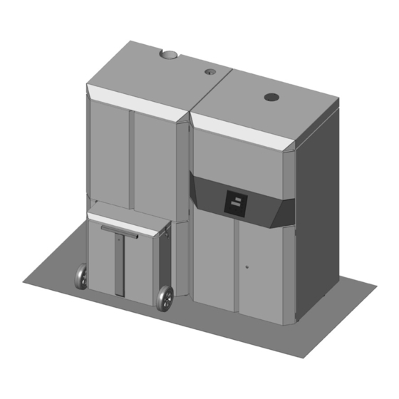
10 - ASSEMBLY OF AESTHETICS UNIT OF REFILL TANK Refill tank For convenience, the panels are identified with the numbers in the picture. REFILL TANK AESTHETICS UNIT Technical Dept. - All rights reserved - Reproduction is prohibited... - Page 70 10 - ASSEMBLY OF AESTHETICS UNIT OF REFILL TANK Locate the right side panel “11” and insert the holes “y” at the base of the panel on the pins “k” on the structure of the tank. ASSEMBLY OF RIGHT-HAND SIDE PANEL (REFILL TANK)
- Page 71 10 - ASSEMBLY OF AESTHETICS UNIT OF REFILL TANK The central instrument panel “E” with control panel and pressure gauge has already been connected to the hydraulic kit and printed circuit board (see dedicated pages). Once the right panel has been mounted, it can be assembled on the structure of the tank by engaging parts “g”...
- Page 72 10 - ASSEMBLY OF AESTHETICS UNIT OF REFILL TANK The top panel “9” has the same fastening system as central panel “E”. Insert the hooks “g” in the holes “f” on the structure of the tank. Use screw “y” (provided) to secure the top of the panel “9”. ASSEMBLY OF TOP PANEL (REFILL TANK)
- Page 73 10 - ASSEMBLY OF AESTHETICS UNIT OF REFILL TANK The bottom door “A” is already fitted with hinges (detail “t”) to be fastened onto the structure of the tank using the holes present (detail “u”) and the screws provided. ASSEMBLY OF DOOR (REFILL TANK) IMPORTANT: Door “8”...
- Page 74 10 - ASSEMBLY OF AESTHETICS UNIT OF REFILL TANK In order to fasten cover “12” already fitted with hinges (detail “t”) it is necessary to fasten it first to the holes “u” in the structure of the tank (with the screws provided) then engage the ring on piston “x” on pin “z”. Repeat this procedure for the second piston. ASSEMBLY OF DOOR (REFILL TANK)
-
Page 75: Assembly Of Aesthetics Unit Of Manual Tank
11 - ASSEMBLY OF AESTHETICS UNIT OF MANUAL TANK MANUAL TANK For convenience, the panels are identified with the numbers in the picture. MANUAL TANK AESTHETICS UNIT Technical Dept. - All rights reserved - Reproduction is prohibited... - Page 76 11 - ASSEMBLY OF AESTHETICS UNIT OF MANUAL TANK Locate the right side panel ‘’12’’ and insert the holes ‘’y’’ at the base of the panel on the pins ‘’k’’ on the structure of the tank. ASSEMBLY OF RIGHT-HAND SIDE PANEL (MANUAL TANK) The central instrument panel ‘’p’’...
- Page 77 11 - ASSEMBLY OF AESTHETICS UNIT OF MANUAL TANK The top panel ‘’10’’ has the same fastening system as central panel ‘’p’’ . Insert the hooks ‘’g’’ in the holes ‘’f’’ on the structure of the tank. Use screw ‘’y’’ (provided) to secure the top of the panel ‘’10’’ . ASSEMBLY OF TOP PANEL (MANUAL TANK) At this point, locate the two bottom doors “8”...
- Page 78 11 - ASSEMBLY OF AESTHETICS UNIT OF MANUAL TANK Fasten the rear panel “14” onto the structure of the tank with the screws provided. ASSEMBLY OF REAR PANEL (MANUAL TANK) In order to fasten the cover ‘’13’’ , which is already fitted with hinges (detail ‘’t’’), attach it first to the holes (detail ‘’u’’) on the structure of the tank (with the screws provided) and then engage the ring of the piston ‘’x’’...
- Page 80 Via La Croce n°8 33074 Vigonovo di Fontanafredda (PN) – ITALY Telefono: +39 0434/599599 r.a. Fax: +39 0434/599598 Internet: www.mcz.it e-mail: info.red@mcz.it 8901317400 REV. 0 06/11/2013...
Need help?
Do you have a question about the LOGIKA 25 and is the answer not in the manual?
Questions and answers