Table of Contents
Advertisement
Quick Links
Advertisement
Table of Contents

Related Manuals for Asus 5U Tower Chassis Kit AK34


Summary of Contents for Asus 5U Tower Chassis Kit AK34
- Page 1 AK34 5U Tower Chassis Kit User Guide...
- Page 2 ASUS has been advised of the possibility of such damages arising from any defect or error in this manual or product.
-
Page 3: Table Of Contents
About this guide ... vii ASUS Contact Information ... viii Chapter 1: Product introduction ... 1-1 1.1 Package contents ... 1-2 1.1.1 ASUS AK34 chassis kit ... 1-2 1.1.2 Standard items ... 1-2 1.1.3 Optional item ... 1-2 1.2 Overview ... 1-3 1.3 Front panel features ... -
Page 4: Contents
Contents 2.6.2 Installing a long expansion card ... 2-17 2.6.3 Removing an expansion card ... 2-18 2.7 Removable components ... 2-19 2.7.1 Chassis fan ... 2-19 2.7.2 Roller wheels ... 2-20 2.7.3 Power supply modules ... 2-21 2.8 Connecting the cables ... 2-22 Appendix: Troubleshooting ...A-1 A.1 Simple fixes ... -
Page 5: Notices
Notices Federal Communications Commission Statement This device complies with FCC Rules Part 15. Operation is subject to the following two conditions: • This device may not cause harmful interference, and • This device must accept any interference received including interference that may cause undesired operation. -
Page 6: Electrical Safety
Safety information Electrical Safety IMPORTANT • Before installing or removing signal cables, ensure that the power cables for the system unit and all attached devices are unplugged. • To prevent electrical shock hazard, disconnect the power cable from the electrical outlet before relocating the system. •... -
Page 7: About This Guide
About this guide Audience This user guide is intended for system integrators, and experienced users with at least basic knowledge of configuring a server. Contents This guide contains the following parts: 1. Chapter 1: System overview This chapter describes the general features of the AK34 barebone server. -
Page 8: Asus Contact Information
ASUS COMPUTER INTERNATIONAL (America) Address: General Fax: General Email: Technical Support Support Fax: General Support: Notebook Support: Web Site: Support Email: ASUS COMPUTER GmbH (Germany and Austria) Address: General Email: General Fax: Technical Support Support Hotlines: Support Fax: Support Email: Web Site: viii... - Page 9 Chapter 1 This chapter describes the general features of the AK34 chassis kit. It includes sections on front panel, rear panel, and internal features. ASUS AK34 chassis kit...
-
Page 10: Chapter 1: Product Introduction
• chassis intrusion cable • power cable 3. Component screws 4. ASUS AK34 Chassis Kit User Guide 1.1.3 Optional item • ASUS AK34 5U Rackmount Rail Kit If any of the above items is damaged or missing, contact your retailer. -
Page 11: Overview
The chassis supports an extended ATX form factor ASUS motherboards. See the motherboard dimension requirements on page 2-4. Refer to the succeeding sections for a brief description of the basic components that are pre-installed in the chassis. -
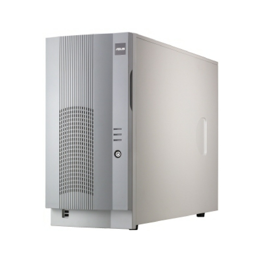
Page 12: Front Panel Features
Front panel features The AK34 chassis kit displays a stylish front bezel with lock. The bezel covers the system components on the front panel and serves as security. Open the bezel to access the front panel components. The power and reset buttons, LED indicators, CD-ROM drive, floppy drive, and two USB ports are located on the front panel. -
Page 13: Rear Panel Features
Slot for motherboard rear panel I/O Expansion slots System with standard power supply module Standard power supply module ASUS AK34 chassis kit AC IN socket (110V/220V autoswitching) AC Power LED 12cm fan vent Chassis lock Chassis intrusion switch (underneath) -
Page 14: Internal Features
Internal features The chassis kit includes the basic components as shown in the picture below. The power supply area differs depending on the power supply module that came with the server you purchased. System with standard power supply module 1. Power supply module 2. -
Page 15: Led Information
Power LED Blinking HDD Access LED Blinking Message LED Blinking Redundant power module LED ASUS AK34 chassis kit Status Description System power ON Suspend mode No activity Read/write data into the HDD Normal; no incoming event ASMS indicates a HW monitor event... - Page 16 Chapter 1: Product introduction...
- Page 17 Chapter 2 This chapter describes the internal hardware components and provides the installation procedures for additional system components. ASUS AK34 chassis kit...
-
Page 18: Chapter 2: Hardware Setup
Preparation Before proceeding, prepare everything that you might need to facilitate installation. 2.1.1 Tools to use 1. Phillips head screw driver 2. Flat head screw driver 2.1.2 System components and devices to install The following items are the basics that you need to install into the chassis kit. -
Page 19: Removing And Installing The Side Cover
2. Slide the cover toward the front until it snaps in place. 3. Tighten the thumb screws to secure the cover. ASUS AK34 chassis kit Hole on the side of the chassis Hook on the cover... -
Page 20: Motherboard Installation
2.3.1 Motherboard dimensions This chassis kit supports an ASUS motherboard that measures 12x12 inches (30.5 x 30.5 cm). Motherboards of smaller sizes will fit into the system chassis. Refer to the motherboard user guide for more information on the system requirements. -
Page 21: Placement Direction And Screw Holes
The following figure shows the specific locations of the standoffs (indicated by black circles) inside the chassis. These standoffs should match with the holes on the motherboard as pointed out above. Metal plate Standoff ASUS AK34 chassis kit... -
Page 22: Installing The Motherboard
2.3.3 Installing the motherboard 1. Remove the temporary metal shield on the rear panel (beside the chassis fan) that covers the rear I/O slot opening. 2. Install the rear I/O shield that came with the motherboard package. Orient the I/O shield such that the openings for the mouse and keyboard ports are aligned to the top of the chassis fan. -
Page 23: Installing 5.25-Inch Drives
To remove the front panel assembly: 1. Use a flat-head screwdriver to detach the hooked tabs from the left side of the front panel. ASUS AK34 chassis kit Hooked tab... -
Page 24: Installing A 5.25-Inch Drive
2. Pull and swing the left edge of the front panel outward. 3. Unhook the hinge-like tabs from the holes on the right side of the front panel to completely detach the front panel assembly from the chassis. 2.4.2 Installing a 5.25-inch drive To install a 5.25-inch drive: 1. - Page 25 (such as a CD/DVD- ROM drive) into the bay until it is in place. The drive is in place when the screw holes on the drive align with the holes on the side of the bay. ASUS AK34 chassis kit...
- Page 26 5. Secure the drive to the bay using the screwless drive bay lock that you removed earlier. a. Match the two pegs on the lock to the holes on the drive bay. b. Turn the knob 45º clockwise until it clicks on the reference point near the “locked icon.”...
- Page 27 Insert the four hinge-like tabs to the holes on the right edge of the chassis. b. Swing the front panel to the left and fit the four (4) hooked tabs to the left side of the chassis until the tabs snap in place. ASUS AK34 chassis kit Hinge-like tab 2-11...
-
Page 28: Installing Hard Disk Drives
Installing hard disk drives The five internal hard disk drive (HDD) bays include removable trays for installing 3.5-inch hard disk drives. You need to remove the side cover to access the drive bays. See section “2.2 Removing and installing the side cover”... - Page 29 5. Carefully insert the drive tray into the bay until you hear a click indicating that the tray is in place. The drive tray is correctly placed when its front edge aligns with the bay edge. ASUS AK34 chassis kit Pegs 2-13...
- Page 30 6. Connect one end of a 40-pin IDE cable to the IDE connector on the drive. Connect the other end to an availble IDE connector on the motherboard. Each drive tray has a designated IDE cable to ensure better air flow and cable placement.
-
Page 31: Installing Or Removing An Expansion Card
The card lock flips up. Card lock lever 2. Slide out the metal bracket opposite the PCI slot where you wish to install the expansion card. You may use a flat-head screwdriver to easily remove the bracket. ASUS AK34 chassis kit Card lock 2-15... - Page 32 3. Install the expansion card making sure that it is properly seated on the slot. 4. Press the end of the card lock marked “LOCK” to secure the card on the slot. A light click indicates that the card is locked in place. Refer to the card documentation for the card configuration details, and to the motherboard user guide in case you need to configure any jumpers after installing the expansion card.
-
Page 33: Installing A Long Expansion Card
3. Slide in the card down until it is properly seated on the slot. 4. Secure the card using the screwless lock on the card guide. Screwless lock ASUS AK34 chassis kit Plastic long-card support 2-17... -
Page 34: Removing An Expansion Card
2.6.3 Removing an expansion card To remove an expansion card: 1. Release the card lock. a. Press the card lock lever. b. The card lock flips up. Card lock lever 2. Pull out the card from the PCI slot. 3. Press the end of the card lock marked “LOCK” to return it in place. 2-18 Card lock Chapter 2: Hardware setup... -
Page 35: Removable Components
2. Use a flat screwdriver to push the pin locks on the four corners of the fan from the inside of the chassis. Chassis fan cable Pin lock (tail-end) 3. Pull out the pin locks from the rear panel. 4. Remove the chassis fan. Pin lock ASUS AK34 chassis kit 2-19... -
Page 36: Roller Wheels
2.7.2 Roller wheels The chassis comes with four roller wheels for convenient transport. Each wheel has a brake lock to stabilize the chassis in place. To remove the chassis wheels: 1. Lay the chassis in its side. 2. Use a Phillips screwdriver to remove the screws that secure the wheels to the bottom of the chassis. -
Page 37: Power Supply Modules
1. Remove the screw that secures the power module to the chassis. 2. Press down the rubber lever to release the power module. 3. Pull out the power module from the chassis. 500W Redundant Power Module ASUS AK34 chassis kit 2-21... -
Page 38: Connecting The Cables
Connecting the cables The chassis includes power and signal cables that you need to connect to the motherboard and to the devices that you will install. Most of the cables for the chassis kit are already connected upon shipment. When installing system devices and connecting cables, make sure that all cables are routed properly for better system stability and performance. - Page 39 This appendix lists the common problems that you may encounter while using the server. It lists the possible causes of the problems and offers solutions. You may refer to this part and try to solve simple problems before calling customer support. ASUS AK34 chassis kit...
-
Page 40: Appendix: Troubleshooting
Simple fixes Some problems that you may encounter are not due to defects on the system or the components. These problems only requires simple troubleshooting actions that you can perform by yourself. Problem The power LED on the server or on the monitor do not light up The keyboard does not work The mouse does not work... - Page 41 The system continuously beeps after it was turned on The message “Non-system disk or disk error” appears Network connection not available ASUS AK34 chassis kit Action 1. Check the memory modules and make sure you installed the DIMMs the system supports.
- Page 42 Appendix: Troubleshooting...
Need help?
Do you have a question about the 5U Tower Chassis Kit AK34 and is the answer not in the manual?
Questions and answers