
Subscribe to Our Youtube Channel
Related Manuals for Asus Gaming Machine Chassis Kit VENTO 3600


Summary of Contents for Asus Gaming Machine Chassis Kit VENTO 3600
-
Page 1: User Guide
Gaming Machine Chassis Kit User Guide 1 5 - 0 6 7 0 0 8 4 0 0 1 5 - 0 6 7 0 0 8 4 0 0 1 5 - 0 6 7 0 0 8 4 0 0 1 5 - 0 6 7 0 0 8 4 0 0 1 5 - 0 6 7 0 0 8 4 0 0 VENTO 3600... - Page 2 Product warranty or service will not be extended if: (1) the product is repaired, modified or altered, unless such repair, modification of alteration is authorized in writing by ASUS; or (2) the serial number of the product is defaced or missing.
-
Page 3: Table Of Contents
Contents Notices ... iv Safety information ... v About this guide ... vi ASUS contact information ... viii Chapter 1: Chapter 1: Chapter 1: Chapter 1: Chapter 1: Product introduction Product introduction Product introduction Product introduction Product introduction Welcome! ... 2 Package contents ... -
Page 4: Notices
Notices Federal Communications Commission Statement Federal Communications Commission Statement Federal Communications Commission Statement Federal Communications Commission Statement Federal Communications Commission Statement This device complies with Part 15 of the FCC Rules. Operation is subject to the following two conditions: • This device may not cause harmful interference, and •... -
Page 5: Safety Information
Safety information Electrical safety Electrical safety Electrical safety Electrical safety Electrical safety • To prevent electrical shock hazard, disconnect the power cable from the electrical outlet before relocating the system. • When adding or removing devices to or from the system, ensure that the power cables for the devices are unplugged before the signal cables are connected. -
Page 6: About This Guide
About this guide This user guide contains the general information and installation instructions for the ASUS VENTO 3600 chassis kit. This guide is intended for experienced users and integrators with hardware knowledge of personal computers. How this guide is organized... - Page 7 Conventions Conventions Conventions Conventions Conventions To make sure that you perform certain tasks properly, take note of the following symbols used throughout this manual. W A R N I N G : W A R N I N G : Information to prevent injury to yourself when trying to W A R N I N G : W A R N I N G : W A R N I N G :...
-
Page 8: Asus Contact Information
Technical Support Telephone (General) (Notebook) Support fax Support e-mail ASUS COMPUTER GmbH (Germany and Austria) ASUS COMPUTER GmbH (Germany and Austria) ASUS COMPUTER GmbH (Germany and Austria) ASUS COMPUTER GmbH (Germany and Austria) ASUS COMPUTER GmbH (Germany and Austria) Address... - Page 9 Chapter 1 This chapter gives a general description of the ASUS VENTO 3600 chassis kit. The chapter lists the system features and introduces the front and rear panels, and the internal components. A S U S V E N T O 3 6 0 0...
-
Page 10: Chapter 1: Product Introduction
The ASUS VENTO 3600 blends efficient functionality with aesthetic design to bring your gaming experience to new heights of performance and style! The colorful and innovative design exclusively by ASUS lets you break away from the usual cube-shaped machines and transport yourself into the virtual future. -
Page 11: System Specification
System specification D r i v e b a y s D r i v e b a y s D r i v e b a y s D r i v e b a y s D r i v e b a y s E x p a n s i o n s l o t s E x p a n s i o n s l o t s E x p a n s i o n s l o t s... -
Page 12: Exploded Drawing
Exploded drawing Cable management kit 120 mm System fan Top panel 5.25” Drive bay locks 5.25” External drive bays (drives not included) Magic Mask ® 5.25” Drive bay covers Side vent for air duct Side panel 10. Side swivel 11. Expansion slot locks 12. -
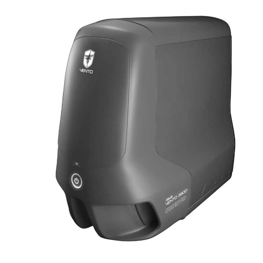
Page 13: Front Panel Features
Front panel features The VENTO 3600 chassis displays a stylish front panel. The power button, LEDs, USB ports, and audio ports are located on the front panel. Flip the Magic Mask disk drive/s. Front panel (external) Front panel (external) Front panel (external) Front panel (external) Front panel (external) Top panel... -
Page 14: Side Panel Features
Side panel features The side panel includes the side swivel, which allows access for the installation of internal components. The side panel also features vent holes with an air duct to pull cool air directly to the components. Side vent for air duct Side swivel Cool LED Rear panel features... -
Page 15: Internal Features
Internal features The VENTO 3600 chassis includes the basic components as shown. Power supply slot 120 mm system fan vent Motherboard mounting panel Expansion slot covers Chassis intrusion sensor A S U S V E N T O 3 6 0 0 A S U S V E N T O 3 6 0 0 A S U S V E N T O 3 6 0 0 A S U S V E N T O 3 6 0 0... - Page 16 1 - 8 1 - 8 1 - 8 1 - 8 1 - 8 C h a p t e r 1 : P r o d u c t i n t r o d u c t i o n C h a p t e r 1 : P r o d u c t i n t r o d u c t i o n C h a p t e r 1 : P r o d u c t i n t r o d u c t i o n C h a p t e r 1 : P r o d u c t i n t r o d u c t i o n...
- Page 17 This chapter provides step-by-step instructions on how to install devices and components in the ASUS VENTO 3600. A S U S V E N T O 3 6 0 0 A S U S V E N T O 3 6 0 0...
-
Page 18: Preparation
Preparation Basic components to install Basic components to install Basic components to install Basic components to install Basic components to install You need to install the following components to the VENTO 3600 chassis kit. Motherboard Power supply unit (PSU) Hard disk drive 5.25-inch drive(s) Floppy disk drive(s) Expansion card(s) - Page 19 Locate and remove three screws that secure the left side cover to the chassis. Keep the screw for later use. Turn the side swivel to about 45º clockwise to release the side panel. Push the side panel to the direction of the arrow. Tilt the side panel, then lift and set aside.
-
Page 20: Installing The Power Supply Unit (Psu)
Installing the power supply unit (PSU) We recommend that you install a standard ATX PSU with at least 350 W power output. To install a PSU: Orient the PSU to the PSU slot. Slide the PSU into the slot until it snugly fits the metal rail. -
Page 21: Installing The Motherboard
Installing the motherboard • The VENTO 3600 supports standard ATX and micro ATX (mATX) motherboards. • Refer to the motherboard user guide for detailed instructions on installing a CPU, heatsink and fan assembly, memory, and other components to the motherboard. Lay the chassis down on a stable surface. -
Page 22: Installing A Hard Disk Drive
Drive the required number of screws with a Phillips screwdriver to secure the motherboard to the chassis. The photo shows the motherboard installed in the chassis. Installing a hard disk drive The chassis kit supports two IDE/ Serial ATA hard disk drives through a detachable hard disk drive cage. -
Page 23: Installing An Ide Hard Disk Drive
2.5.1 2.5.1 2.5.1 Installing an IDE hard disk drive Installing an IDE hard disk drive Installing an IDE hard disk drive 2.5.1 2.5.1 Installing an IDE hard disk drive Installing an IDE hard disk drive To install an I D E I D E I D E I D E... - Page 24 Re-install the HDD cage to the chassis. Slide in the HDD cage to the bay assembly rails. Carefully push the HDD cage in the direction of the arrow until it snaps to indicate that it is secured to the chassis. Connect a 40-pin IDE cable to the IDE connector at the back of the drive.
-
Page 25: Installing A Sata Hard Disk Drive
2.5.2 2.5.2 Installing a SATA hard disk drive Installing a SATA hard disk drive 2.5.2 2.5.2 2.5.2 Installing a SATA hard disk drive Installing a SATA hard disk drive Installing a SATA hard disk drive To install a S e r i a l A T A S e r i a l A T A S e r i a l A T A S e r i a l A T A hard disk drive:... -
Page 26: Installing 5.25-Inch Drives
Installing 5.25-inch drives Make sure to unplug the power cable before installing or removing any system components. Failure to do so may cause severe damage to the motherboard and other system components! The system comes with four 5.25-inch drive bays located on the upper front part of the chassis. - Page 27 The Magic Mask ® lifts to reveal the face plates of the drive bays. Slide the drive bay lock to the left, towards the sign, to unlock the drive bay. Carefully insert the optical drive into the bay, then push it inward until it is completely flushed to the chassis front panel.
-
Page 28: Installing Additional 5.25-Inch Drive(S)
2.6.2 2.6.2 2.6.2 2.6.2 2.6.2 Installing additional 5.25-inch drive(s) Installing additional 5.25-inch drive(s) Installing additional 5.25-inch drive(s) Installing additional 5.25-inch drive(s) Installing additional 5.25-inch drive(s) You may install additional 5.25-inch optical drives, zip, or floppy disk drives in the three remaining bays. Configure your optical drive as Master/Slave device before installing it to the drive bay. - Page 29 Carefully insert the optical drive into the bay, then push it inward until it is completely flushed to the chassis front panel. Align the screw holes as shown. Slide the drive bay lock to the right, towards the lock the drive bay and to secure the drive in place.
-
Page 30: Installing A 3.5-Inch Floppy Disk Drive
Connect a 4-pin power plug from the power supply unit to the drive power connector. Installing a 3.5-inch floppy disk drive You may install up to two floppy disk drives in the 3.5-inch drive bay under the 5.25-inch drive bays. Configure your optical drive as Master/Slave device before installing it to the drive bay. - Page 31 Using a screwdriver, push the knock down metal cover in and out of the chassis until it is removed. Slide the drive bay lock to the right, towards the unlock the drive bay. Carefully insert the floppy disk drive into the bay, then push it inward until it is completely flushed to the chassis front panel.
- Page 32 Slide the drive bay lock to the left, towards the lock the drive bay and to secure the drive in place. The drive bay lock has a screwless design that allows you to secure the floppy disk drive without screws. However, we recommend that you still drive screws into the bay to ensure a firm fit.
-
Page 33: Installing Expansion Cards
Installing expansion cards The VENTO 3600 chassis kit comes with six PCI slots and one AGP slot for installation of expansion cards. Make sure to unplug the power supply before installing or removing an expansion card(s). Failure to do so may cause severe damage to both the motherboard and the components. - Page 34 Align the card connector with the slot, then press firmly until the card is completely seated on the slot. Secure the card with the lock tab you removed earlier. 2 - 1 8 2 - 1 8 2 - 1 8 2 - 1 8 2 - 1 8 C h a p t e r 2 : B a s i c i n s t a l l a t i o n...
-
Page 35: Replacing The Side Cover
Replacing the side cover After installing all components and connecting the necessary cables, replace the side cover by following these instructions. To replace the side cover: Match the side panel hooks to the chassis rail edge. Fit the side panel toward the chassis until it fits. - Page 36 Replace the cable management kit. 2 - 2 0 2 - 2 0 2 - 2 0 2 - 2 0 2 - 2 0 C h a p t e r 2 : B a s i c i n s t a l l a t i o n C h a p t e r 2 : B a s i c i n s t a l l a t i o n C h a p t e r 2 : B a s i c i n s t a l l a t i o n C h a p t e r 2 : B a s i c i n s t a l l a t i o n...
Need help?
Do you have a question about the Gaming Machine Chassis Kit VENTO 3600 and is the answer not in the manual?
Questions and answers