
Related Manuals for Asus Vento 7700


Summary of Contents for Asus Vento 7700
- Page 1 VENTO 7700 Gaming Machine Chassis Kit User Guide 1 5 G 0 6 7 2 4 5 0 0 0 1 5 G 0 6 7 2 4 5 0 0 0 1 5 G 0 6 7 2 4 5 0 0 0...
- Page 2 Product warranty or service will not be extended if: (1) the product is repaired, modified or altered, unless such repair, modification of alteration is authorized in writing by ASUS; or (2) the serial number of the product is defaced or missing.
-
Page 3: Table Of Contents
Installing a 5.25-inch drive ..........2-10 Installing a 3.5-inch floppy disk drive ......... 2-13 Installing expansion cards ........... 2-15 Replacing the side panel ............. 2-17 ASUS contact information ............. 2-18 i i i i i i i i i i i i i i i... -
Page 4: Notices
Notices Federal Communications Commission Statement Federal Communications Commission Statement Federal Communications Commission Statement Federal Communications Commission Statement Federal Communications Commission Statement This device complies with Part 15 of the FCC Rules. Operation is subject to the following two conditions: • This device may not cause harmful interference, and •... -
Page 5: Safety Information
Safety information Electrical safety Electrical safety Electrical safety Electrical safety Electrical safety • To prevent electrical shock hazard, disconnect the power cable from the electrical outlet before relocating the system. • When adding or removing devices to or from the system, ensure that the power cables for the devices are unplugged before the signal cables are connected. -
Page 6: About This Guide
About this guide This user guide contains the general information and installation instructions for the ASUS VENTO 7700 chassis kit. This guide is intended for experienced users and integrators with hardware knowledge of personal computers. How this guide is organized... - Page 7 Chapter 1 This chapter gives a general description of the ASUS VENTO 7700 chassis kit. The chapter lists the system features and introduces the front and rear panels, and the internal components. A S U S V E N T O 7 7 0 0...
-
Page 8: Welcome
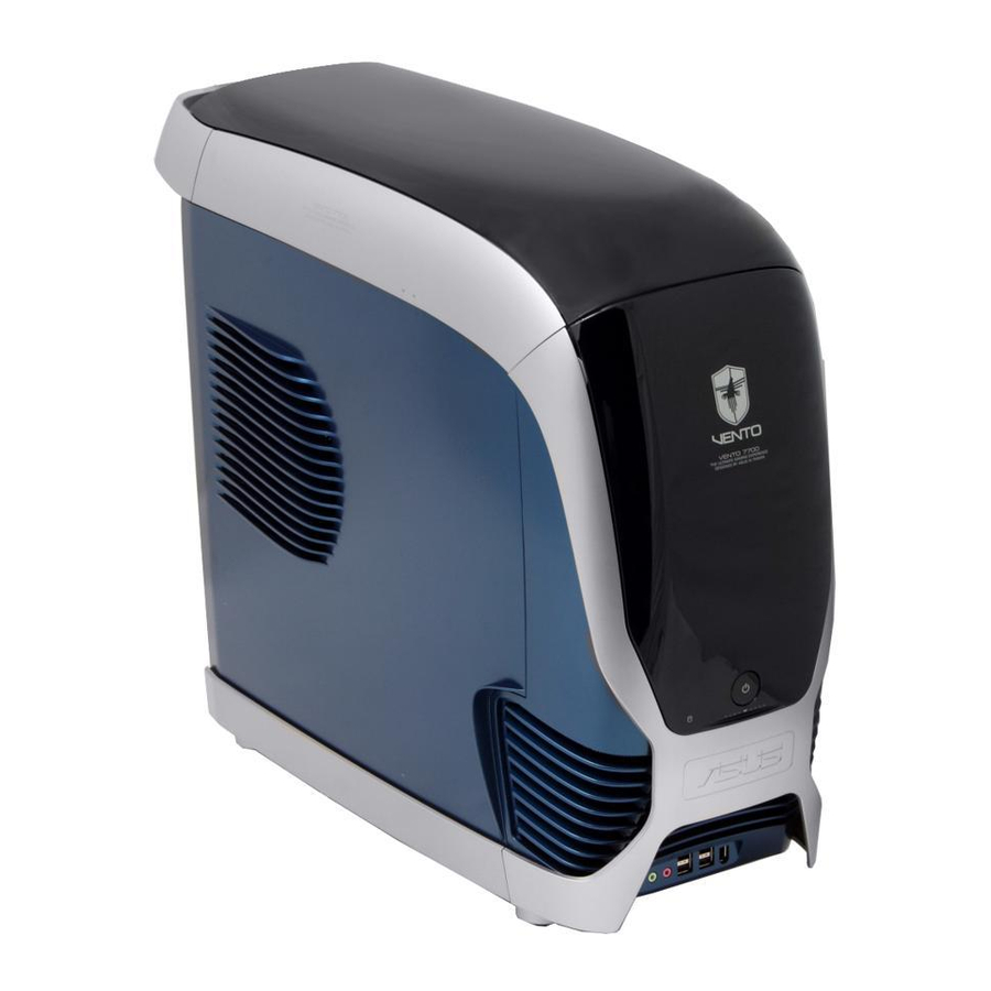
The ASUS VENTO 7700 blends efficient functionality with aesthetic design to bring your gaming experience to new heights of performance and style! The colorful and innovative design exclusively by ASUS lets you break away from the usual cube-shaped machines and transport yourself into the virtual future. -
Page 9: Exploded Drawing
Exploded drawing Chassis assembly Rubber pads for chassis feet Screws for the rear handle Bezel assembly Rear handle Right side panel Top panel 10. Screws for the right side panel Front chassis feet 11. Left side panel Rear chassis feet A S U S V E N T O 7 7 0 0 A S U S V E N T O 7 7 0 0 A S U S V E N T O 7 7 0 0... -
Page 10: Internal Features
Internal features The VENTO 7700 chassis includes the basic components as shown. Power supply slot 5.25-inch drive bays 80 mm system fan vent 3.5-inch FDD bays Motherboard mounting panel Internal HDD drive bays Expansion slot covers 1 - 4 1 - 4... - Page 11 This chapter provides step-by-step instructions on how to install devices and components in the ASUS VENTO 7700. A S U S V E N T O 7 7 0 0 A S U S V E N T O 7 7 0 0...
-
Page 12: Chapter 2: Basic Installation
Basic components to install Basic components to install Basic components to install Basic components to install Basic components to install You need to install the following components to the VENTO 7700 chassis kit. Motherboard Power supply unit (PSU) Hard disk drive (s) 5.25-inch drive(s) - Page 13 Push the side panel towards the rear panel. Slightly tilt down the side panel, then slide it out of the chassis. A S U S V E N T O 7 7 0 0 A S U S V E N T O 7 7 0 0 A S U S V E N T O 7 7 0 0 A S U S V E N T O 7 7 0 0 A S U S V E N T O 7 7 0 0...
-
Page 14: Installing The Power Supply Unit (Psu)
Installing the power supply unit (PSU) We recommend that you install a standard ATX PSU with at least 350 W power output. To install a PSU: Orient the PSU to the PSU slot. Slide the PSU into the slot until it snugly fits the metal rail. -
Page 15: Installing The Motherboard
Installing the motherboard • The VENTO 7700 supports standard ATX and micro ATX (mATX) motherboards. • Refer to the motherboard user guide for detailed instructions on installing a CPU, heatsink and fan assembly, memory, and other components to the motherboard. -
Page 16: Installing A Hard Disk Drive
The photo shows the motherboard installed in the chassis. Installing a hard disk drive The chassis supports three IDE/ Serial ATA hard disk drives. I n t e r n a l h a r d d i s k I n t e r n a l h a r d d i s k I n t e r n a l h a r d d i s k I n t e r n a l h a r d d i s k... -
Page 17: Installing An Ide Hard Disk Drive
2.5.1 2.5.1 Installing an IDE hard disk drive Installing an IDE hard disk drive 2.5.1 2.5.1 2.5.1 Installing an IDE hard disk drive Installing an IDE hard disk drive Installing an IDE hard disk drive To install an I D E I D E I D E I D E hard disk drive:... - Page 18 Connect a 40-pin IDE cable to the IDE connector at the back of the drive then connect the other end to the IDE connector on the motherboard. Refer to the motherboard user guide for the location of the IDE connector. Connect a 4-pin power plug from the power supply unit to the power connector at the back of the drive.
-
Page 19: Installing A Serial Ata Hard Disk Drive
2.5.2 2.5.2 2.5.2 Installing a Serial ATA hard disk drive Installing a Serial ATA hard disk drive Installing a Serial ATA hard disk drive 2.5.2 2.5.2 Installing a Serial ATA hard disk drive Installing a Serial ATA hard disk drive To install a S e r i a l A T A S e r i a l A T A S e r i a l A T A... -
Page 20: Installing A 5.25-Inch Drive
Installing a 5.25-inch drive Make sure to unplug the power cable before installing or removing any system components. Failure to do so may cause severe damage to the motherboard and other system components! The system comes with four 5.25-inch drive bays located on the upper front part of the chassis. - Page 21 The Magic Mask ® lifts to reveal the drive bay covers. Press the lock tabs in the direction of the arrows to release the drive bay cover from the bezel. Using a screwdriver, push the knock down metal cover in and out of the chassis until it is removed.
- Page 22 Carefully insert the optical drive into the bay, then push it inward until it is completely flushed into the chassis. Align the screw holes as shown. Press down the drive bay lock to secure the optical drive to the chassis. Connect a 40-pin IDE cable to the IDE connector at the back of the drive then connect the other...
-
Page 23: Installing A 3.5-Inch Floppy Disk Drive
Installing a 3.5-inch floppy disk drive You may install up to two floppy disk drives in the 3.5-inch drive bay under the 5.25-inch drive bays. To install a floppy disk drive(s): Select the drive bay you intend to use. Press the lock tabs in the direction of the arrows to release the drive bay cover from the bezel. - Page 24 Carefully insert the floppy disk drive into the bay, then push it inward until it is completely flushed into the chassis. Make sure that the FDD screw holes are aligned with the FDD bay screw holes. Press down the drive bay lock to secure the floppy disk drive to the chassis.
-
Page 25: Installing Expansion Cards
Installing expansion cards The VENTO 7700 chassis kit comes with seven (7) slots for installation of expansion cards. Make sure to unplug the power supply before installing or removing an expansion card(s). Failure to do so may cause severe damage to both the motherboard and the components. - Page 26 Align the card connector with the slot, then press firmly until the card is completely seated on the slot. On the rear panel, push the slot cover lock tab to secure the card. 2 - 1 6 2 - 1 6 2 - 1 6 2 - 1 6 2 - 1 6...
-
Page 27: Replacing The Side Panel
Replacing the side panel After installing all components and connecting the necessary cables, replace the side panel by following these instructions. To replace the side panel: Slide the top edge of the side panel into the chassis. Make sure that the side panel handle aligns with the curve on the bezel. -
Page 28: Asus Contact Information
ASUSTeK COMPUTER INC. (Asia-Pacific) Hotline +886-2-2894-3447 +886-2-2890-7698 Support Online http://vip.asus.com/eservice/techserv.aspx Website http://www.asus.com ASUS COMPUTER INTERNATIONAL (America) ASUS COMPUTER INTERNATIONAL (America) ASUS COMPUTER INTERNATIONAL (America) ASUS COMPUTER INTERNATIONAL (America) ASUS COMPUTER INTERNATIONAL (America) General Product Support General Product Support General Product Support...
Need help?
Do you have a question about the Vento 7700 and is the answer not in the manual?
Questions and answers