Table of Contents
Advertisement
Quick Links
Visit us online at
www.uswatersystems.com
Green Wave Ultra Iron, Sulfur and
Manganese Removal Saltless Water
Owners Manual
Models:
385-GWU-1000, 385-GWU-1500, 385-GWU-2000
REVISION #
1.1
REVISION DATE
May 4, 2015
Conditioning System
US Water Systems Corporate Office
1209 Country Club Road
Indianapolis, IN 46234
1-800-608-8792
info@uswatersystems.com
Advertisement
Table of Contents

Subscribe to Our Youtube Channel
Related Manuals for US Water Systems 385-GWU-1000


Summary of Contents for US Water Systems 385-GWU-1000
- Page 1 Green Wave Ultra Iron, Sulfur and Manganese Removal Saltless Water Conditioning System Owners Manual Models: 385-GWU-1000, 385-GWU-1500, 385-GWU-2000 US Water Systems Corporate Office 1209 Country Club Road Indianapolis, IN 46234 1-800-608-8792 REVISION # info@uswatersystems.com REVISION DATE May 4, 2015...
-
Page 2: Table Of Contents
Be sure to check the entire system for any shipping damage or parts loss. Also note damage to the shipping cartons. Contact US Water Systems at 1-800-608-8792 to report any shipping damage within 24 hours of de- livery. Claims made after 24 hours may not be honored. -
Page 3: Proper Installation
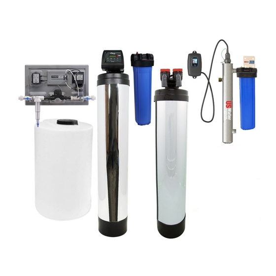
Installation, Operation and Maintenance Manual 385-GWU-1000, 385-GWU-1500, 385-GWU-2000 Proper Installation This water treatment system must be properly installed and located in accordance with the Installation Instructions before it is used or the warranty will be void. Do not install or store where it will be sweat-solder connections, as required by ... - Page 4 Installation, Operation and Maintenance Manual 385-GWU-1000, 385-GWU-1500, 385-GWU-2000 GreenWave Tank Introduction The GreenWave Ultra system provides protection from scale formation throughout the home. The GreenWave system should be installed after the Fusion Oxi-Gen system to treat your entire home, both hot and cold water, or it can be located directly before a water heater or other device (e.g.
- Page 5 Installation, Operation and Maintenance Manual 385-GWU-1000, 385-GWU-1500, 385-GWU-2000 US Water UV Light Introduction This point-of-use system allows for simple installation and operation due to its high output lamp and compact reactor. The reactor is an axial flow design with superior hydraulics, com- pact design and 1”...
- Page 6 US Water UV Light Introduction Operation The US Water Systems UV comes with a feature laden controller that incorporates both the lamp driver (ballast) and control features in one water-tight case. CAUTION: Prior to performing any maintenance on your UV system, you must always disconnect the power.
- Page 7 US Water UV Light Introduction USWATER 5.0 & USWATER 6.0 Power-up Sequence Upon start up, the 5.0 & 6.0 controller will run through a diagnostic start-up and the sequence will be displayed as follows on the color LCD: Next, the controller checks for the installation of any optional modules that may be installed on the system.
- Page 8 Screen.
- Page 9 US Water UV Light Introduction USWATER 6.0 Operational Screens On systems that have the UV module installed (and on all USWATER6.0 systems), the default screen shows the % UV Intensity. At any point during operation the user is able to scroll through the % UV Intensity, Lamp life remaining an d QR Code s c r een s b y s i m p l y p r es s i n g t h e b u t t o n l o c at ed on the front of the controller.
- Page 10 US Water UV Light Introduction Once the UV output drops below 56%, the numbers and warning sign switch to red and a 15 second intermit- tent audible chirp is given off by the ballast. When the output drops below 51%, the display switches to a solid red and a constant audible signal is provided.
- Page 11 USWATER5.0 & USWATER6.0 Failure Modes The US Water Systems controller continuously monitors your UV system and if there is a problem with the system the controller will provide both a visual and audible signal indicating the specific fault that may be adversely affecting the operation of your system.
- Page 12 Users with a camera phone equipped with the correct reader application can scan the image of the QR code and over a wireless network connect to a US Water Systems web page in the phone's browser. US Water Systems' QR webpage has information on how to purchase replacement components as well as a helpful video directory on system servicing (i.e.
-
Page 13: System Overview And Specifications
The Fusion Superfilter Oxi-Gen Hydrogen Peroxide System is the answer to practically any iron, rust, sulfur, hydrogen sulfide or manganese problem, and is backed with our 90-Day 100% Satisfaction Guarantee. US Water Systems guarantees 100% iron, manganese and sulfur removal with its Fusion Superfilter Oxi-Gen System which utilizes Hydrogen Peroxide or H2O2. -
Page 14: Overhead Installation Drawing
Installation, Operation and Maintenance Manual 385-GWU-1000, 385-GWU-1500, 385-GWU-2000 Installed System Overhead View... - Page 15 Installation, Operation and Maintenance Manual 385-GWU-1000, 385-GWU-1500, 385-GWU-2000 Installed System Overhead and View...
- Page 16 Installation, Operation and Maintenance Manual 385-GWU-1000, 385-GWU-1500, 385-GWU-2000 Installed System Overhead and View...
-
Page 17: How Your Fusion Superfilter Oxi-Gen Treatment System Works
4-5 days. The typical frequency is 1-3 days. Contact US Water Systems and a Certified Water Specialist will be able to determine the frequency that can be used when considering the feed water contaminant levels. The factory... -
Page 18: Importance Of Contaminant Removal Prior To The Greenwave Tank
Installation, Operation and Maintenance Manual 385-GWU-1000, 385-GWU-1500, 385-GWU-2000 The Importance of Contaminant Removal Prior to the GreenWave Tank Iron and Manganese Just as with conventional water softening media, the GreenWave media needs to be protected from excess levels of certain metals that can easily coat the active surface, reducing its effectiveness over time. -
Page 19: Fusion Superfilter Installation Instructions And Specifications
Installation, Operation and Maintenance Manual 385-GWU-1000, 385-GWU-1500, 385-GWU-2000 Fusion Superfilter Installation Instructions and Specifications WATER PRESSURE: A minimum of 20 pounds of water pressure is required for re- generation valve to operate effectively. ELECTRICAL FACILITIES: An uninterrupted alternating current (A/C) supply is required. - Page 20 Installation, Operation and Maintenance Manual 385-GWU-1000, 385-GWU-1500, 385-GWU-2000 Superfilter Tank and Control Valve Preparation 2. Lubricate the distributor O-ring and the tank O-ring. Then install the upper basket (may look different than the pictures below) on the bottom of the valve by lining up the tabs then turning the basket clockwise to lock it in place.
-
Page 21: Injection Panel Installation Instructions
Installation, Operation and Maintenance Manual 385-GWU-1000, 385-GWU-1500, 385-GWU-2000 Injection Panel Installation Instructions 1. Layout the parts for the injection panel, then find the location where the panel will be in- stalled. Install the stainless steel mounting bar. A level can be used to make sure the bar is installed properly. - Page 22 Installation, Operation and Maintenance Manual 385-GWU-1000, 385-GWU-1500, 385-GWU-2000 Injection Panel Installation Instructions 2. Hang the injection panel on the mounting bar. 3. If your hot water tank is electric, turn off the power to it to avoid damage to the element in the tank.
- Page 23 Installation, Operation and Maintenance Manual 385-GWU-1000, 385-GWU-1500, 385-GWU-2000 Injection Panel Installation Instructions 6. Now install the outlet plumbing using the Union Adaptor and tighten the union collars with channel locks. Do not over tighten these unions. 7. Now install the strainer filter and the strainer sump. If the feed water is high in turbidity, use the #100 mesh strainer filter.
- Page 24 Installation, Operation and Maintenance Manual 385-GWU-1000, 385-GWU-1500, 385-GWU-2000 Injection Panel Installation Instructions 8. There is a ball valve on the bottom of the strainer filter sump. This ball valve should be closed during operation. This ball valve and be used to flush the strainer filter sump period- ically.
-
Page 25: Superfilter Carbon Tank Installation Instructions
Installation, Operation and Maintenance Manual 385-GWU-1000, 385-GWU-1500, 385-GWU-2000 Superfilter Carbon Tank Installation Instructions Any solder joints being soldered near the valve must be done before connecting any piping to the valves. Always leave at least 6" (152 mm) between the control valve and joints being soldered when soldering pipes that are connected to the valves. - Page 26 Installation, Operation and Maintenance Manual 385-GWU-1000, 385-GWU-1500, 385-GWU-2000 Superfilter Carbon Tank Installation Instructions 2. Attach the outlet plumbing to the Superfilter control valve. Be sure to check the stamped arrows on the valve and bypass for inlet/outlet orientation. NOTE: Put the Fusion Carbon Superfilter in the bypass position.
-
Page 27: Injection Panel Chemical Solution Tank Installation Instructions
Installation, Operation and Maintenance Manual 385-GWU-1000, 385-GWU-1500, 385-GWU-2000 Injection Panel Chemical Solution Tank Installation Instructions 1. Place the chemical solution tank close to the injection panel. Drill a 1/4” hole in the top of the chemical tank. Push the 1/4” tubing in the hole in the tank. - Page 28 Installation, Operation and Maintenance Manual 385-GWU-1000, 385-GWU-1500, 385-GWU-2000 Injection Panel Chemical Solution Tank Installation Instructions 3. Be sure the weighted strainer on the 1/4” tubing until it can be seen in the slots in the weighted strainer. Then drop the strainer in the tank and push the 1/4” tubing through the hole in the tank until the weighted strainer is about 1”...
-
Page 29: Chemical Injection Panel Start-Up Instructions
Installation, Operation and Maintenance Manual 385-GWU-1000, 385-GWU-1500, 385-GWU-2000 Chemical Injection Panel Start-up Instructions 1. Plug the chemical injection panel in the wall. Pour the supplied Hydrogen Peroxide into the chemical solution tank. Unplug the pump power cord from the PCM on the injection panel and attach it to an extension cord that is energized. -
Page 30: Micron Sediment Filter Installation Instructions
Installation, Operation and Maintenance Manual 385-GWU-1000, 385-GWU-1500, 385-GWU-2000 5 Micron Sediment Filter Installation Instructions 1. Install the 5 Micron sediment filter after the Fusion Carbon Superfilter. The sediment filter is marked “IN” and “OUT” on the top of the housing. - Page 31 Installation, Operation and Maintenance Manual 385-GWU-1000, 385-GWU-1500, 385-GWU-2000 Sediment Filter Installation Instructions 3. Now mount the filter housing to the wall using the appropriate fasteners for your wall materi- al. It is preferred that this is mounted on a secured board or wall stud as it will be heavy when full of water.
- Page 32 Installation, Operation and Maintenance Manual 385-GWU-1000, 385-GWU-1500, 385-GWU-2000 Sediment Filter Installation Instructions 1. Now install the filter in the filter housing by removing the sump from the housing. 2. There is a notch in the bottom of the sump that will center the filter in the housing. Unwrap the filter (5 Micron) and install it in the sump.
- Page 33 Installation, Operation and Maintenance Manual 385-GWU-1000, 385-GWU-1500, 385-GWU-2000 Sediment Filter Installation Instructions 4. Now install the sump in the filter cap and turn it clockwise to tighten the filter. Once it is hand tight, use the supplied wrench to tighten it an additional 1/4-1/2 turn.
-
Page 34: Greenwave Tank Installation Instructions
Installation, Operation and Maintenance Manual 385-GWU-1000, 385-GWU-1500, 385-GWU-2000 GreenWave Tank Installation Instructions 1. Place the GreenWave tanks in the desired location on a flat level surface. 2. Make sure that the tank head is tightened securely by hand tightening—Do Not Use a Wrench. Hand- tight is recommended. -
Page 35: Us Water Uv Light Installation Instructions
Installation, Operation and Maintenance Manual 385-GWU-1000, 385-GWU-1500, 385-GWU-2000 US Water UV Light Installation Instructions Overview Figure 3. Recommended Installation... - Page 36 Step 4: If the water supply flow rate is unknown, it is recommended that you use a flow restrictor so that the rated flow of your particular US Water Systems system is not exceeded and the UV dose is not compromised.
- Page 37 Installation, Operation and Maintenance Manual 385-GWU-1000, 385-GWU-1500, 385-GWU-2000 US Water UV Light Installation Instructions Step 9: You can now gently remove the quartz sleeve from its packaging being VERY careful not to touch the length with your hands. The use of cotton gloves (not included) is recommended for this procedure as oils from our hands can leave residue on the sleeve and lamp which can ultimately block the UV light from getting to the water.
- Page 38 Installation, Operation and Maintenance Manual 385-GWU-1000, 385-GWU-1500, 385-GWU-2000 US Water UV Light Installation Instructions Figure 5. UV Sensor Installation Figure 6. IEP Connection Step 12: Th e r eac t o r i s n ow read y f o r w at er f l o w . Wh en al l p l u m b i n g c o n n ec t i o n s h av e b een completed you should check for any possible leaks.
- Page 39 Installation, Operation and Maintenance Manual 385-GWU-1000, 385-GWU-1500, 385-GWU-2000 US Water UV Light Installation Instructions Figure 7. UV Lamp Connection Step 15: Carefully insert the UV lamp into the reactor sliding it inside the quartz sleeve located in- side the reactor (do not drop the lamp into the reactor). Affix the lamp connector into the gland nut by in- serting the connector into the nut and turning the connector approximately ¼...
- Page 40 Installation, Operation and Maintenance Manual 385-GWU-1000, 385-GWU-1500, 385-GWU-2000 US Water UV Light Installation Instructions Figure 9. Ground Screw Connection Step 17: Your system is now ready to be plugged into the appropriate GFCI protected outlet . The unit will be plugged in during the startup procedure. DO NOT plug in at this time.
-
Page 41: Micron Sediment Filter Installation Instructions
Installation, Operation and Maintenance Manual 385-GWU-1000, 385-GWU-1500, 385-GWU-2000 1 Micron Sediment Filter Installation Instructions 1. Install the 1 Micron sediment filter after the US Water UV light. The sediment filter is marked “IN” and “OUT” on the top of the housing. - Page 42 Installation, Operation and Maintenance Manual 385-GWU-1000, 385-GWU-1500, 385-GWU-2000 1 Micron Sediment Filter Installation Instructions 3. Now mount the filter housing to the wall using the appropriate fasteners for your wall materi- al. It is preferred that this is mounted on a secured board or wall stud as it will be heavy when full of water.
- Page 43 Installation, Operation and Maintenance Manual 385-GWU-1000, 385-GWU-1500, 385-GWU-2000 1 Micron Sediment Filter Installation Instructions 1. Now install the filter in the filter housing by removing the sump from the housing. 2. There is a notch in the bottom of the sump that will center the filter in the housing. Unwrap the filter (1 Micron) and install it in the sump.
- Page 44 Installation, Operation and Maintenance Manual 385-GWU-1000, 385-GWU-1500, 385-GWU-2000 1 Micron Sediment Filter Installation Instructions 4. Now install the sump in the filter cap and turn it clockwise to tighten the filter. Once it is hand tight, use the supplied wrench to tighten it an additional 1/4-1/2 turn.
-
Page 45: Control Valve Keypad Functions And Backwash Initiation
Installation, Operation and Maintenance Manual 385-GWU-1000, 385-GWU-1500, 385-GWU-2000 Fusion Carbon Superfilter Key Pad Configuration SETTINGS This function is to enter the basic set up infor- mation required at the time of installation. MANUAL This function is to initiate an immediate or REGEN delayed manual regeneration. -
Page 46: Control Valve Programming
3) Set the “Time of Day” and the “Date”. 4) Set the “Regen Days” to the desired value (contact US Water Systems for help with the proper frequency. Typically 3 days will work for most applications). 5) The “Gallons” parameter should be set to “Off”. -
Page 47: System Start-Up Instructions
Installation, Operation and Maintenance Manual 385-GWU-1000, 385-GWU-1500, 385-GWU-2000 System Start-up Instructions 1. Once all the plumbing has been connected, slowly open the main water shutoff valve. Make sure the inlet and outlet valves on the injection panel are open. Open a spigot downstream of the entire system to release the air. -
Page 48: H2O2 Injection Rate Adjustment Instructions (Bubble Method)
385-GWU-1000, 385-GWU-1500, 385-GWU-2000 Hydrogen Peroxide Injection Rate Adjustment Instructions US Water Systems uses the “bubble method”. This is a visual method that works best for quick and reliable H2O2 injection rates. The GreenWave tank should be in the bypass position during this procedure. -
Page 49: Greenwave Tank Startup Instructions
Installation, Operation and Maintenance Manual 385-GWU-1000, 385-GWU-1500, 385-GWU-2000 GreenWave Tank Startup Instructions WARNING! Be sure the peroxide injection pump is adjusted properly before bringing the GreenWave tank into service. Iron or other contaminants that are removed by the perox- ide injection system can damage the GreenWave media. It is crucial that the peroxide system is operating properly. -
Page 50: What To Expect And Routine Maintenance
If this does occur, it is easily eradicated with a chlorination well “shock” procedure. Ask a US Water Systems representative about our well sanitizing kits. WARNING! If a well is being chlorinated, the Carbon Superfilter and GreenWave tank should be in the bypass position. -
Page 51: Boil Test
Installation, Operation and Maintenance Manual 385-GWU-1000, 385-GWU-1500, 385-GWU-2000 Boil Test The GreenWave tank media can be checked by using the following boil test method. The GreenWave tank cannot be checked by using a hardness test be- cause the elements that make up hardness will still be present in the water. A hardness test will always show hardness because the GreenWave tank does not remove hardness, it only isolates it and prevents it from scaling. -
Page 52: Maintenance Schedule
Installation, Operation and Maintenance Manual 385-GWU-1000, 385-GWU-1500, 385-GWU-2000 Maintenance Schedule Component Action Frequency Existing Well Pressure Tank Drain tank until the water runs clear. 1-6 Months Panel Sediment Filter Drain the filter at the dump valve period- Monthly ically to flush any solids that may accu- mulate. -
Page 53: Limited Lifetime Warranty
GENERAL PROVISIONS residential place of installation of this GreenWave Ultra This warranty does not apply to any commercial or Water Conditioning System, US WATER SYSTEMS, INC. industrial installations or to any part of the water warrants the following: conditioner which has been subjected to misuse, neglect, LIFETIME COVERAGE alteration or accident;...
Need help?
Do you have a question about the 385-GWU-1000 and is the answer not in the manual?
Questions and answers