Table of Contents
Advertisement
Quick Links
Advertisement
Table of Contents

Related Manuals for US Water Systems 320-PUV-MAX-10


Summary of Contents for US Water Systems 320-PUV-MAX-10
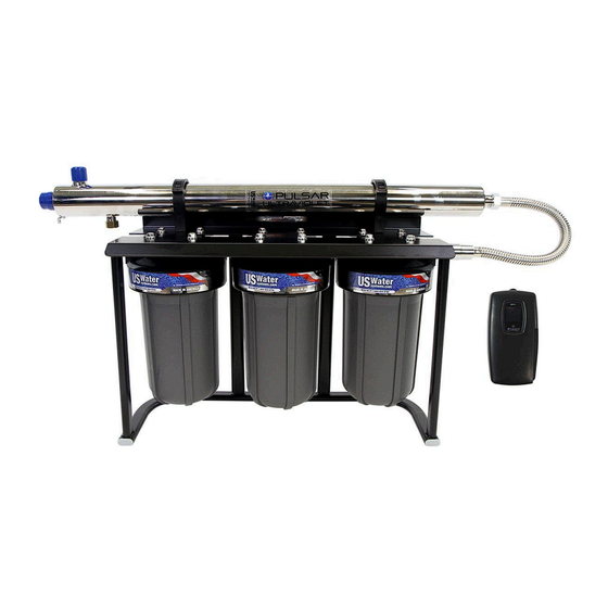
- Page 1 Pulsar Max Ultraviolet Disinfection System 320-PUV-MAX-10...
-
Page 2: Table Of Contents
Table of Contents Unpacking and Inspection ..................3 Safety Guide ...................... 3 System Layout ......................4 Features and Benefits ....................5 Filter Assembly Installation ..................6 UV Installation ......................10 Filter Startup Instructions ..................14 Diagnostic Steps ..................... 15 Filter Cartridge Replacement Instructions ............... 16 Cleaning/Replacing the Quartz Sleeve .............. -
Page 3: Unpacking And Inspection
Be sure to check the entire unit for any shipping damage or lost parts. Also note damage to the shipping cartons. Contact US Water Systems at 1-800-608-8792 to report any shipping damage within 24 hours of delivery. Claims made after 24 hours may not be honored. -
Page 4: System Layout
System Layout Need help? 1.800.390.5936 www.uswatersystems.com... -
Page 5: Features And Benefits
Features and Benefits • Black and Gray Filter Housings - Made in the USA • Best Materials - Built with chemical resistant reinforced Polypropylene • High Pressure Housings - Pressure tested well beyond industry standards: 100°F (37.8°C) and 90 psi (6.2 bar). •... -
Page 6: Filter Assembly Installation
Filter Assembly Installation Install the filter system in the desired location in the water treatment system. The caps are marked "IN" and OUT" on the top of the housings. The system will be built when it arrives flowing left to right. This can be disassembled and changed to match a right to left flow application. - Page 7 Shut off the water and release the water pressure at the lowest sink or spigot. Cut the pipe and connect it to the filter. Connect the inlet plumbing to the inlet on the filter housing. Tighten with an adjustable wrench. Use Teflon tape to wrap the MPT threads on the provided stainless steel flex connec- tor.
- Page 8 Remove the sumps from the filter and install the . Ensure that the filters are installed in the correct order. The system utilizes a step down filtration method so the 5 Micron Magna will be the first, followed by the 1 Micron Magna, and finally the Interceptor.A very small amount of silicone grease or water can be used to lubricate the O-rings on the filter.
- Page 9 Lubricate the O-ring on the filter housing sump and install it. Tighten the filter sump hand tight. That should be adequate. Do not use abrasive tools to tighten the hous- ing or damage may occur. NOTE: Adding a little bit of lubricant/silicone to the sump threads will make the sump easier to remove when replacing the filter.
-
Page 10: Uv Installation
UV Installation The reactor can be installed either horizontally or vertically using the clamps provi- ded. Vertical installation is the preferred method with the inlet at the bottom (lamp connection at the top) as it allows any air that may be in the lines to be easily purged from the system. - Page 11 Use the supplied fasteners to mount the UV reactor to wood or drywall. If mounting to an alternate material, you will need to purchase the proper corresponding fasten- ers. For water supplies where the maximum flow rate is unknown, a flow restrictor is recommended so that the rated flow of your particular UV system is not exceeded.
- Page 12 Mount the controller to the wall so it is above or beside the reactor to ensure that no moisture can deposit on any of the connections. Always mount the controller vertically. Do not plug the controller power cord in before the last step. Always hold UV lamps by their ceramic ends, not by the lamp quartz.
- Page 13 10. Plug the lamp connector into the lamp. Note the keying for proper alignment. Insert the lamp connector into the gland nut and turn the connector approximately 1/4 turn to lock the connector to the gland nut. 11. Tighten the captive ground screw to the ground lug on the UV reactor to ensure proper grounding.
-
Page 14: Filter Startup Instructions
Filter Startup Instructions Open a faucet or spigot down stream of the filter. Slowly open the water shutoff valve and let the filter fill. Air will be pushed out of the system through the open spigot or faucet downstream. Once there is no air coming out of the faucet or spigot, turn the water supply on fully and shut the faucet or spigot. -
Page 15: Diagnostic Steps
Diagnostic Steps Pulsar systems come with a feature laden controller that incorporated both the lamp driver (ballast) and control features in one water-tight case. A full color LCD screen provides the user with a detailed description of the system's per- formance in addition to providing any applicable fault messages and system diagnostics. -
Page 16: Filter Cartridge Replacement Instructions
Filter Cartridge Replacement Instructions Shut off the water supply Open the faucet or spigot closest to the filter housing and allow all the water to empty from the plumbing systems WARNING! If the pressure is not released, the filter sump will be very difficult to get loose. - Page 17 Lubricate the O-rings and install the new filter in the filter housing cap. Lubricate the O-Ring for the sump and the sump threads with food grade silicone grease. Install the filter sump in the filter cap by turning it counter-clockwise until it is hand tight.
-
Page 18: Cleaning/Replacing The Quartz Sleeve
Cleaning/Replacing the Quartz Sleeve Depending on the water quality, the quartz sleeve may require periodic cleaning. At a minimum, the quartz sleeve should be cleaned on an annual basis. The following steps outline a basic cleaning procedure. Turn off the main water inlet valve (and / or turn off the water pump). Disconnect the power cord of the UV system from the electrical outlet. -
Page 19: Replacing The Lamp
Replacing the Lamp Ensure the system is powered down and the UV controller is turned off. Remove the lamp connector from the reactor by pushing the lamp connector in and turning it 1/4 turn counter-clockwise. Disconnect the lamp connector from the lamp. CAUTION: The lamp may be hot. -
Page 20: Warranty
US WATER SYSTEMS, INC.. for transportation and standard labor charg- es. Damages due to environmental issues To obtain warranty service, call or write: or improper installation are not covered.
Need help?
Do you have a question about the 320-PUV-MAX-10 and is the answer not in the manual?
Questions and answers