Table of Contents
Advertisement
Quick Links
Visit us online at
www.uswatersystems.com
US Water Systems Matrixx Liquid Chlorination
Owners Manual
Models:
150-FLCS-XXXX
REVISION #
1.2
REVISION DATE: February 3, 2020
Water Treatment System
US Water Systems, Inc.
1209 Country Club Road
Indianapolis, IN 46234
1-800-608-8792
info@uswatersystems.com
www.uswatersystems.com
US Water Systems Corporate Office
1209 Country Club Road
Indianapolis, IN 46234
1-800-608-8792
info@uswatersystems.com
Advertisement
Table of Contents

Subscribe to Our Youtube Channel
Related Manuals for US Water Systems Matrixx 150-FLCS Series


Summary of Contents for US Water Systems Matrixx 150-FLCS Series
- Page 1 Visit us online at www.uswatersystems.com US Water Systems Matrixx Liquid Chlorination Water Treatment System Owners Manual Models: 150-FLCS-XXXX US Water Systems, Inc. 1209 Country Club Road Indianapolis, IN 46234 1-800-608-8792 info@uswatersystems.com www.uswatersystems.com US Water Systems Corporate Office 1209 Country Club Road...
-
Page 2: Table Of Contents
Be sure to check the entire system for any shipping damage or parts loss. Also note damage to the shipping cartons. Contact US Water Systems at 1-800-608-8792 to report any shipping damage within 24 hours of delivery. Claims made after 24 hours may not be honored. -
Page 3: Proper Installation, Before Starting Installation, Where To Install The Treatment System
Proper Installation This water treatment system must be properly installed and located in accordance with the Installation Instructions before it is used or the warranty will be void. Do not install or store where it will be ex- Maximum allowable inlet water pressure is •... -
Page 4: System Overview And Specifications
System Overview and Specifications Liquid Chlorination systems can be installed for several reasons. Typically they are used for bacteria control or oxidation. Chlorination systems are applied to surface water or shallow wells to remove bacteria in the water from surface runoff and rotting vegetation or from shallow wells with ever changing conditions. -
Page 5: How The Liquid Chlorination Treatment System Works
How the Liquid Chlorination Water Treatment System Works The Liquid Chlorination water treatment system injects chlorine into the water stream to remove iron, sulfur, manganese and bacteria from water source. Chlorine is injected into the water stream proportionally. The chemical injection control panel will engage the pump based on the flow rate of the feed source water and the settings on the pump control. -
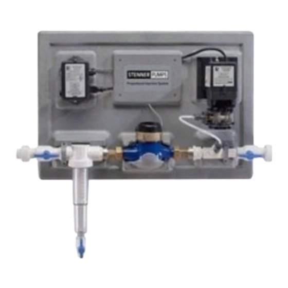
Page 6: System Components
Injection Panel Installation 1. Layout the parts for the injection panel, then find the location where the panel will be in- stalled. Install the stainless steel mounting bar. A level can be used to make sure the bar is installed properly. This bar should be secured to the wall studs or wood backing plate that is secured to the wall studs. - Page 7 Injection Panel Installation 2. Hang the injection panel on the mounting bar. 3. Now install the inlet plumbing from the sediment filter to the left side of the injection panel. Use the 3/4” Union Adaptors to connect to the panel. These adaptors are designed for 3/4” PVC.
- Page 8 Injection Panel Installation 4. Now install the outlet plumbing using the Union Adaptor and tighten the union collars with channel locks. Do not over tighten these unions. 5. Now install the strainer filter and the strainer sump. If the feed water is high in turbidity, use the #100 mesh strainer filter.
-
Page 9: Retention Tank Installation Instructions
Injection Panel Installation 1. There is a ball valve on the bottom of the strainer filter sump. This ball valve should be closed during operation. This ball valve and be used to flush the strainer filter sump period- ically. This can be done by placing a bucket under the ball valve and opening the valve un- til the sump strainer is clear. - Page 10 Retention Tank Installation...
-
Page 11: Carbon Filter Installation
Carbon Filter Specifications Overall Model Tank Size System Height LWS-100 9” X 48” 55.00” 49.25” 9” LWS-150 10” X 54” 61.00” 55.25” 10” Inlet-Outlet Connection LWS-200 12” X 52” 59.00” 53.25” 12” Height LWS-250 13” X 54” 61.00” 55.25” 13” LWS-300 14”... - Page 12 Carbon Filter Flow Diagram...
- Page 13 Carbon Filter Installation Fusion Backwashing Filter Tank Installation Instructions WATER PRESSURE: A minimum of 30 pounds of water pressure is required for the backwashing valve to operate effectively. ELECTRICAL FACILITIES: An uninterrupted alternating current (A/C) supply is required. Note: Other volt- ages are available.
- Page 14 Carbon Filter Installation 3) Place a piece of duct tape over the riser tube so no media enters the riser while filling. 4) Use the Blue Funnel provided, to pour the gravel and media into the tank. Pour the gravel into the tank first, then pour in the carbon.
- Page 15 Carbon Filter Installation 6) Lubricate the distributor O-ring and the outer tank O-ring. 7) Install the upper basket on the bottom of the valve by lining up the tabs then turning the basket clockwise to lock it in place. Place the upper basket over the distributor tube and push the valve on the tank.
- Page 16 Carbon Filter Installation If the hot water tank is electric, turn off the power to it to avoid damage to the element in the tank. If the supply is a private well, turn the power off to the pump and then shut off the main water shut off valve.
- Page 17 Carbon Filter Installation 5. Connect the drain hose to the valve and secure it with a hose clamp. Run the drain hose to the nearest laundry tub, floor drain or approved air gap fitting. The drain can be ran overhead or down along the floor.
- Page 18 Carbon Filter Installation New Sounds There may be new sounds when the system operates. The Backwash cycle lasts up to 25 minutes. During this time, water can be heard running intermittently to the drain. Automatic Hard Water Bypass During Regeneration The regeneration cycle can last 25 to 30 minutes, after which treated water service will be re- stored.
- Page 19 System Regeneration Using Onboard Buttons Normal Operation 1. Home Display The home display will alternate between the Time of Day and Gallons left until the next regen- eration. The meter will count down to zero (0000) and then regenerate at the scheduled time set.
- Page 20 Programming Using Onboard Buttons 1. To enter Main Menu, press the Menu/Enter button. (Time of Day will flash) 2. To set the Time of Day, press the Set/Change button. (First digit will flash) To change digit value, press • the Set/Change button. To accept the digit value, press •...
- Page 21 Programming Using Water Logix App US Water Systems has moved into the 21st century with our latest line of equipment that utiliz- es the Water Logix Bluetooth System Control Application for iPhone and Android. This app al- lows the user to control every aspect of the water systems from convenience of a smart phone.
- Page 22 Programming Using Water Logix App Dashboard Parameters that can be changed are indicated with orange font. To change a parameter tap on the orange font then use the keyboard that appears to change the value. Time of Day: Tap on the “Time of Day” box. A box will appear that allows you to set the unit to the time that matches the device being used to program the unit.
- Page 23 Programming Using Water Logix App Advanced Settings Parameters that can be changed are indicated with orange font. To change a parameter tap on the orange font then use the keyboard that appears to change the value. Backwash: This should be set to “10” mins and should not be changed. Rest: This should be set to “2”...
- Page 24 Programming Using Water Logix App Status and History The Status and History screen shows current conditions of the system as well as flow rate and usage history. There are two parameters that can be reset; Total Regenerations: This parameter shows how many times the system has regenerat- ed since it was put in service or since the last time the value was reset.
- Page 25 Contact Information The Contact Information screes is used to provide the customer with contact info for US Water Systems. There is a link to the website and to our support team. Regeneration Initiation There are two options for regenerating the system. Tap on the desired option and press “OK”.
-
Page 26: Chlorine Injection Setting
Chlorine Injection Setting To set the chlorine injection rate you will use the previously installed sample port (sample port should be installed in the outlet piping after the retention tank). 1. Set the proportional control on the Stenner injection panel (gray wall mount panel) to 40% (there is a dial on the little black box (PCM) that the pump is plugged in to). -
Page 27: What To Expect And Routine Maintenance
What To Expect and Routine Maintenance Now that the US Water Pond and Surface Water Treatment system has been installed here are a few things to ex- pect; 1. The system will produce iron, sulfur and bacteria free water immediately after installation. Depending on the raw water quality there may be contaminants built up in the water heater, plumbing system and other devices. -
Page 28: Maintenance Schedule
Maintenance Schedule Component Action Frequency Replacement Part # Existing Well Pressure Drain tank until the water runs 1-6 Months Tank clear. Injection Panel Pump Inspect pump tube and replace 1-5 Years 411-EC30F-2 Tube as needed. F Tube. Injection Panel Injection Remove the injection fitting and 1-6 Months 411-UCDBINJ... -
Page 29: Layout Drawing
Flow Schematic... -
Page 30: Warranty
TEN YEAR COVERAGE control of US WATER SYSTEMS, INC.. Valve and Electronics To obtain warranty service, call or write: US WATER SYS- We warrant that for ten (10) years from the date of installation, we will TEMS, INC.
Need help?
Do you have a question about the Matrixx 150-FLCS Series and is the answer not in the manual?
Questions and answers