Table of Contents
Advertisement
Quick Links
Visit us online at
www.uswatersystems.com
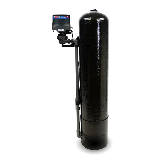
US Water Systems Flexx Oxi-Gen
Aeration Iron and Sulfur Removal
Owners Manual
Models:
FX-150, FX-250
REVISION #
1.2
REVISION DATE : January 2, 2020
System
US Water Systems Corporate Office
1209 Country Club Road
Indianapolis, IN 46234
1-800-608-8792
info@uswatersystems.com
Advertisement
Table of Contents

Related Manuals for US Water Systems Flexx Oxi-Gen FX-150


Summary of Contents for US Water Systems Flexx Oxi-Gen FX-150
- Page 1 Visit us online at www.uswatersystems.com US Water Systems Flexx Oxi-Gen Aeration Iron and Sulfur Removal System Owners Manual Models: FX-150, FX-250 US Water Systems Corporate Office 1209 Country Club Road Indianapolis, IN 46234 1-800-608-8792 REVISION # info@uswatersystems.com REVISION DATE : January 2, 2020...
-
Page 2: Table Of Contents
Be sure to check the entire System for any shipping damage or lost parts. Also note dam- age to the shipping cartons. Contact US Water Systems at 1-800-608-8792 to report any shipping damage within 24 hours of delivery. Claims made after 24 hours may not be honored. -
Page 3: Proper Installation
Proper Installation This water system must be properly installed and located in accordance with the Installation Instructions before it is used or the warranty will be void. Do not install or store where it will be ex- WARNING: Discard all unused parts and •... -
Page 4: About The System
If there is a large amount of free air noticed on the cold water side, there is a possible malfunction of the system and US Water Systems should be contacted to service the unit. -
Page 5: System Dimensions
System Dimensions Model Tank Size FX-150 10” X 54” 61” 52” 10” 21” FX-250 13” X 15” 61” 52” 13” 24” Overall System Height Inlet-Outlet Connection Height Tank Diameter... -
Page 6: Specifications
Specifications Model Number FX-150 FX-250 Tank Size 10” x 54” 13” x 54” Capacity (cu/ft) Gravel Under-bedding 15 lbs 25 lbs Backwash Flow Control (GPM) Service Flow Rates 7 GPM 15 GPM Peak Flow Rates 10 GPM 20 GPM Pressure Drop @ Service Flow 5-7 PSI 5-7 PSI Pressure Drop @ Peak Flow... -
Page 7: How The Water System Works
How the Water System Works • Air is injected into the top of the tank converting ferrous iron to ferric iron and oxidizing sulfur after untreated water has passed through the control valve preventing the control valve from fouling with iron and/or iron. – The Sludge that forms in most Air Injection Systems is simply gone and the iron and sulfur is eradicated with ease. -
Page 8: Where To Install The System
Where To Install The System Place the system as close as possible to A 120 volt electric outlet is needed within 6 • • the pressure tank (well system) or water feet of the system. The transformer has an meter (city water). attached 6 foot power cable. -
Page 9: System Preparation
System Preparation Flexx Oxi-Gen System Tank Preparation WATER PRESSURE: A minimum of 20 pounds of water pressure is required for regener- ation valve to operate effectively. ELECTRICAL FACILITIES: An uninterrupted alternating current (A/C) supply is required. Note: Other voltages are available. Please make sure your voltage supply is compatible with your unit before installation. - Page 10 A helper may be needed to hold the funnel during the filling process. The Gravel is poured in first and the Carbon second. Install all the gravel and carbon that was sent. US Water Systems does NOT send extra me- dia.
- Page 11 System Preparation Lubricate the distributor O-rings on the valve connectors Install the valve on the tank and tighten the connector nuts hand tight. There should- n’t be a need to use tools on these connectors. Hand tight should be sufficient. Install the valve fastening bolt in the bottom of the valve through the support arm bracket.
-
Page 12: Installation Instructions
Installation Instructions If your hot water tank is electric, turn off the power to it to avoid damage to the element in the tank. If you have a private well, turn the power off to the pump and then shut off the main water shut off valve. - Page 13 Installation Instructions 5. Connect the drain hose to the valve and secure it with a hose clamp. Run the drain hose to the nearest laundry tub, floor drain or approved air gap fitting. The drain can be ran overhead or down along the floor. Drain tubing should be a minimum of 1/2” ID. When running the drain overhead it is important that the tubing has no dips or kinks.
- Page 14 Installation Instructions 6. Turn the bypass handle to place the unit in the bypass position. Slowly turn on the main water supply. At the nearest cold treated faucet or spigot, open the faucet and let water run a few minutes or until the system is free of any air or foreign material resulting from the plumbing work.
-
Page 15: Programming The System Using Onboard Buttons
Programming Using Onboard Buttons Plug the transformer into the “P” hole on the valve. The LED screen will be flashing between the time of day and the number of days between backwash cycles. NOTE: The unit will recharge with air every night. The days between a full backwash cycle are what the flashing number represents. - Page 16 Master Programming Using Onboard Buttons To enter Master Programming Mode, press and hold both buttons for 5 seconds. Note: All Master Programming functions have been preset at the factory. Unless a change is desired, it is NOT necessary to enter Master Programming Mode. 1.
- Page 17 Master Programming Using Onboard Buttons 3. Pulse H2O2 Setting (J) The default pulse H2O2 setting is 2. • Setting pulse H2O2 to 0 will disable it. • The maximum value for pulse H2O2 is 4. • Change the digit values using the Set / Change and Menu / Enter buttons as de- •...
-
Page 18: Programming The System Using The Water Logix App
Programming Using Water Logix App US Water Systems has moved into the 21st century with our latest line of equipment that utilizes the Water Logix Bluetooth System Control Application for iPhone and Android. This app allows the user to control every aspect of the water systems from convenience of a smart phone. - Page 19 Programming Using Water Logix App Dashboard Parameters that can be changed are indicated with orange font. To change a parameter tap on the orange font then use the keyboard that appears to change the value. Time of Day: Tap on the “Time of Day” box. A box will appear that allows you to set the unit to the time that matches the device being used to program the unit.
- Page 20 Programming Using Water Logix App Advanced Settings Parameters that can be changed are indicated with orange font. To change a parameter tap on the orange font then use the keyboard that appears to change the value. NOTE: These are factory set and should not be changed without guidance. Air Charge Frequency: This should be set to 1 day.
- Page 21 Programming Using Water Logix App Status and History The Status and History screen shows current conditions of the system as well as flow rate and usage history. There are two parameters that can be reset; Total Regenerations: This parameter shows how many times the system has regen- erated since it was put in service or since the last time the value was reset.
-
Page 22: Regenerating Using The Water Logix App
Programming Using Water Logix App Contact Information The Contact Information screes is used to provide the customer with contact info for US Water Systems. There is a link to the website and to our support team. Regenerating Using the Water Logix App There are two options for regenerating the system. -
Page 23: System Startup
System Start Up With the bypass handle in the bypass position, initiate an immediate regeneration. Ad- vance through the first 4 cycles to cycle 5. This is the backwash cycle. Each cycle can be advanced by touching the “Go To Next Regen Step” button and selecting “OK” to advance to the next cycle. -
Page 24: Water System Features
Water System Features Battery Back-Up (Uses a standard 9-volt alkaline battery.) • During power failures, the battery will maintain the time of day as long as the battery has power. The display is turned off to conserve battery power during this time. To confirm that the battery is working, press either button and the display will turn on for five (5) seconds. -
Page 25: Peroxide Injection System Installation (Optional)
Peroxide Injection System US Water Flexx Oxi-Gen systems can be purchased with a peroxide injection feed for back- washing the carbon. This injection will take place during an air injection cycle. Peroxide is injected during the regeneration process to help “scrub” the carbon and keep the system clean. -
Page 26: About The System
About The System You may notice new sounds as your water System operates. The regeneration cycle lasts up to 120 minutes. During this time, you may hear water running intermittently to the drain. Automatic Hard Water Bypass During Regeneration The regeneration cycle can last 30 to 180 minutes, after which soft water service will be re- stored. -
Page 27: Parts Guide
Power Head Exploded View... - Page 28 Power Head Parts List Description Part Number Powerhead Assy. 20015X100 Circuit Board Assy. 20015X101 Encoder 20001X124 Front Plate 20001X004 Encoder Wheel 20001X007 Main Gear 21001X120 Power Supply 20001X125 Back Plate 20001X005 Lower Front Base For Cover 20111X002 Microswitch 20251X113 Switch Spacer 20111X004 Brine Motor Mount 20111X006...
- Page 29 Control Valve Exploded View...
- Page 30 Control Valve Parts List Description Part No. Piston Assembly Final Rinse 20009X231 10-24 X 13/16 Hex Head 20001X226 Seal and Spacer Kit 20561X253 Bottom Spacer DLFC 5.0 Button 20251X272 DLFC 7.0 Button 20251X273 Flow Control Assembly 5.0 20017X262 Flow Control Assembly 7.0 20017X264 Drain Line Flow Control (DLFC) 22001X100...
- Page 31 Tank Assembly Parts List...
- Page 32 Tank Assembly Parts List Description Part No. Tank Cap Q-7004 Tank Distributor Tube (per foot) 33012X001 10” Black Tank 31054X000 13” Black Tank 31354X000 10” Zip Tie 13” Zip Tie Tank Bracket 20015X011 Basket 33000X003 Tank Adapter 20015X008 13” Tank Extension 20015X002 Requires one of 20561X205 also Flex Oxi-Gen Nut...
- Page 33 Bypass Parts List Description Part No. D15 Bypass 20017X283 1” Female Straight Slip Set 20017X288 1” NPT Elbow Set 20017X284 1” NPT Straight Set 20017X289 Elbow, Vertical Adapter 20017X295 Blank Elbow, Vertical Adapter 20017X294 1/4” NPT Tapped...
- Page 34 Troubleshooting SYMPTOM PROBABLE CAUSE CORRECTION Power supply plugged into Connect to constant power source intermittent or dead power source 1. Fails to Regener- Improper control Reset program settings ate Automatical- valve programming Defective power supply Replace power supply Defective Drive motor Replace motor 2.
-
Page 35: Warranty
Seven Year Valve and Electronics Guarantee US Water Systems will replace any part on the valve or electronics which fails within seven (7) years from date of manufacture, as indicated by the serial number, provided the failure is due to a defect in material or workmanship.
Need help?
Do you have a question about the Flexx Oxi-Gen FX-150 and is the answer not in the manual?
Questions and answers