Sign In
Upload
Manuals
Brands
Omron Manuals
Controller
CK3W-MD71 0 Series
Omron CK3W-MD71 0 Series Manuals
Manuals and User Guides for Omron CK3W-MD71 0 Series. We have
4
Omron CK3W-MD71 0 Series manuals available for free PDF download: Hardware User Manual, User Manual, Quick Start Manual
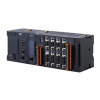
Omron CK3W-MD71 0 Series Hardware User Manual (288 pages)
Programmable Multi-Axis Controller
Brand:
Omron
| Category:
Controller
| Size: 9.58 MB
Table of Contents
Intended Audience
3
Applicable Products
3
Manual Structure
4
Page Structure
4
Special Information
5
Sections in this Manual
7
Table of Contents
8
Terms and Conditions Agreement
13
Warranty, Limitations of Liability
13
Application Considerations
14
Disclaimers
14
Statement of Security Responsibilities for Assumed Use Cases and against Threats
15
Safety Precautions
16
Definition of Precautionary Information
16
Symbols
16
Warning
17
Cautions
19
Precautions for Safe Use
20
Precautions for Correct Use
25
Regulations and Standards
27
Conformance to EU Directives
27
Condition for Compliance with EU Directives
27
Conformance to UL and CSA Standards
28
Conformance to KC Certification
28
Versions
29
Checking Versions
29
Related Manuals
30
Terminology
31
Revision History
32
Introduction to Motion Controllers
33
Features and System Configuration
34
Motion Controller Features
34
Introduction to the System Configurations
34
Support Software
35
Basic Configuration
35
CK3W Unit Configuration
35
Ethercat Network Configuration
36
Basic Configuration
40
CK3W Unit Configuration
40
Ethercat Network Configuration
40
Connecting to the Power PMAC IDE
43
Ethernet Network Configuration
44
CPU Unit
47
Models and Specifications
47
Part Names and Functions
49
Operation Status Indicators
50
Watchdog Output Terminal Block
51
USB Memory Device
53
Power Supply Unit
54
Models and Specifications
54
Part Names and Functions
55
Axis Interface Unit
56
Models and Specifications
56
Part Names and Functions
58
Operation Status Indicators
59
Address Switch Setting
60
Encoder Connector Specifications
60
Encoder Loss Detection
66
Pulse Input Timing Specifications for Digital Quadrature Encoder
67
Input Specifications for Sinusoidal Encoder
69
Outflag Function
71
Amplifier Connector Specifications
72
Output Method
75
Directpwm Output Method
76
Flag Connection Terminal Block Specifications
77
General Digital I/O Connection Terminal Block Specifications
82
Digital I/O Unit
89
Models and Specifications
89
Part Names and Functions
93
Operation Indicators
94
Address Switch Setting
94
Terminal Arrangement
95
I/O Data
96
Analog Input Unit
98
Models and Specifications
98
Part Names and Functions
99
Operation Indicators
100
Address Switch Setting
100
Terminal Arrangement
101
Analog Input Data
102
Input Filter
103
Encoder Input Unit
105
Models and Specifications
105
Part Names and Functions
107
Operation Indicators
107
Address Switch Setting
107
Terminal Arrangement
108
Software Settings
108
Laser Interface Unit
110
Models and Specifications
110
Part Names and Functions
114
Operation Indicators
115
Address Switch Setting
115
Terminal Arrangement
116
XY2-100 Interface
116
SL2-100 Interface
120
PWM Output Function
124
TCR Output Function
126
Software Settings
128
Expansion Master Unit and Expansion Slave Unit
131
Models and Specifications
131
Part Names and Functions
132
Operation Indicators
133
System Configuration
133
Processing at Power on and Power off
136
Power on Operation
136
Power off Operation
136
Fail-Safe Circuits
138
Unit Installation
140
Installation in a Control Panel
140
Connection between Units
144
Mounting to DIN Track
145
DIN Track and Accessories
147
Assembled Appearance and Dimensions
148
Control Panel Installation
153
Temperature
153
Humidity
154
Vibration and Shock
155
Atmosphere
155
Electrical Environment
155
Grounding
160
Wiring
165
Power Supply Wiring
166
Power Supply Unit CK3W-PD048
166
Power Supply Used
166
Applicable Wires
166
Grounding
167
Required Tools
168
Connecting Ferrules
168
Connecting Twisted Wires/Solid Wires
168
Removing Wires
169
CPU Unit Wiring
171
Laying the Ethercat Network
171
Laying the Ethernet Network
176
Watchdog Timer Output Wiring
178
USB Memory Device Connection
181
Axis Interface Unit Wiring
182
Encoder Connector Wiring
182
Amplifier Connector Wiring
188
Flag Terminal Block/General I/O Terminal Block Wiring
190
Digital I/O Unit Wiring
197
Wiring the Terminals
197
Precautions When Connecting a Two-Wire DC Sensor
200
Precautions When Connecting to Digital Output
202
Analog Input Unit Wiring
204
Wiring the Terminals
204
Encoder Input Unit
208
Encoder Connector Wiring
208
Dedicated Cable
208
Laser Interface Unit
210
Galvo Scanner Connector Wiring
210
Laser Connector Wiring
212
Expansion Master Unit and Expansion Slave Unit Wiring
214
Troubleshooting
215
Types of Errors
216
Using the Indicators to Check Errors
217
Indicator Types
217
Procedure for Identifying Errors
217
Troubleshooting for Errors
219
Fatal Errors in the CPU Unit
219
Non-Fatal Errors in the CPU Unit
220
Initialization of CPU Unit Using USB Memory
223
Sys.status Register
224
Sys.status Register List
224
Details of Flags
225
Ethernet/Ip Connection Status Codes and Troubleshooting
234
Inspection and Maintenance
237
Cleaning and Inspection
238
Cleaning
238
Periodic Inspections
238
Maintenance Procedures
240
Unit Replacement Precautions
240
Backup
240
Unit Replacement
240
Appendices
243
A-1 General Specifications
245
A-2 Dimensions
246
A-2-1 CPU Unit
246
CPU Unit
246
A-2-2 Power Supply Unit
247
A-2-3 Axis Interface Unit
247
A-2-4 CK3W-MD and CK3W-AD Units
248
A-2-5 CK3W-ECS and CK3W-GC Units
249
A-2-6 Expansion Master Unit and Expansion Slave Unit
250
A-2-7 End Cover
251
Restrictions on Using the NX-Series Ethercat Coupler Unit
252
OMRON Servo Drive Connection Example
253
A-5 Version Information
254
A-6 How to Read the Lot Number
255
A-7 Supported CIP Objects
256
A-7-1 Identity Object (Class ID: 01 Hex
256
Identity Object (Class ID: 01 Hex
256
A-7-2 Assembly Object (Class ID: 04 Hex
257
TCP/IP Interface Object (Class ID: F5 Hex
258
A-7-4 Ethernet Link Object (Class ID: F6 Hex
259
Software Reference of Encoder Input Unit
263
A-8-1 Gate3[I].Serialencctrl (Serial Encoder Control
263
Gate3[I].Serialencctrl (Serial Encoder Control
263
A-8-2 Gate3[I].Chan[J].Serialencena (Serial Encoder Enable
266
A-8-3 Gate3[I].Chan[J].Serialenccmd (Serial Encoder Command
266
A-8-4 Gate3[I].Chan[J].Serialencdataa (Serial Encoder Data a
269
A-8-5 Gate3[I].Chan[J].Serialencdatab (Serial Encoder Data B
270
A-8-6 Gate3[I].Chan[0].Status (Internal Memory Error Detection
273
Software Reference of Laser Interface Unit
275
Gate3[I].Serialencctrl (Control Register
275
A-9-2 Gate3[I].Chan[J].Dac[0] (Setting of Command Position and Control Command
276
A-9-3 Gate3[I].Chan[J].Dac[1] (Setting of Command Position Compensation Value
277
A-9-3 Gate3[I].Chan[J].Dac[1] (Setting of Command Position Compensa- Tion Value
277
A-9-4 Gate3[I].Chan[J].Serialencdataa (Command Position after Interpolation, Reception Data
277
A-9-4 Gate3[I].Chan[J].Serialencdataa (Command Position after Interpola- Tion, Reception Data
277
A-9-5 Gate3[I].Chan[J].Serialencdatab (Status Data
278
A-9-6 Gate3[I].Chan[0].Compa (PWM Output Setting
279
A-9-7 Gate3[I].Chan[1].Compa (PWM Output Delay Setting
280
A-9-8 Gate3[I].Chan[2].Compa (PWM Output Pulse Count
280
Gate3[I].Chan[0].Compb (TCR Output Command Distance Setting
281
A-9-10 Gate3[I].Chan[1].Compb (TCR Output Comparison Table Setting
281
A-9-11 Gate3[I].Chan[2].Compb (TCR Output Control Register
281
A-9-12 Gate3[I].Chan[3].Compb (TCR Output Status Register
282
A-9-13 Gate3[I].Chan[0].Status (Internal Memory Error Detection
282
Advertisement
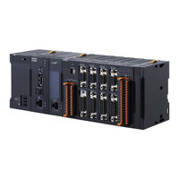
Omron CK3W-MD71 0 Series Hardware User Manual (302 pages)
Programmable Multi-Axis Controller
Brand:
Omron
| Category:
Controller
| Size: 12.07 MB
Table of Contents
Table of Contents
8
Intended Audience
3
Applicable Products
3
Manual Structure
4
Page Structure
4
Special Information
5
Sections in this Manual
7
Table of Contents
8
Terms and Conditions Agreement
13
Warranty, Limitations of Liability
13
Application Considerations
14
Disclaimers
14
Statement of Security Responsibilities for Assumed Use Cases and against Threats
15
Safety Precautions
16
Definition of Precautionary Information
16
Symbols
16
Warning
17
Cautions
21
Precautions for Safe Use
22
Precautions for Correct Use
27
Regulations and Standards
29
Conformance to EU Directives
29
Condition for Compliance with EU Directives
29
Conformance to KC Certification
30
Conformance to UL and CSA Standards
30
Versions
31
Checking Versions
31
Related Manuals
33
Terminology
34
Revision History
35
Introduction to Motion Controllers
37
Features and System Configuration
38
Motion Controller Features
38
Introduction to the System Configurations
38
Basic Configuration
39
Support Software
39
Ethercat Network Configuration
40
Connecting to the Power PMAC IDE
50
Ethernet Network Configuration
51
CPU Unit
55
Models and Specifications
55
Part Names and Functions
58
Operation Status Indicators
59
Watchdog Output Terminal Block
60
USB Memory Device
61
Power Supply Unit
63
Models and Specifications
63
Part Names and Functions
64
Axis Interface Unit
65
Models and Specifications
65
Part Names and Functions
67
Operation Status Indicators
68
Address Switch Setting
69
Encoder Connector Specifications
69
Encoder Loss Detection
75
Pulse Input Timing Specifications for Digital Quadrature Encoder
76
Input Specifications for Sinusoidal Encoder
78
Outflag Function
80
Amplifier Connector Specifications
81
Output Method
84
Directpwm Output Method
85
Flag Connection Terminal Block Specifications
86
General Digital I/O Connection Terminal Block Specifications
91
Digital I/O Unit
98
Models and Specifications
98
Part Names and Functions
102
Operation Indicators
103
Address Switch Setting
103
Terminal Arrangement
104
I/O Data
105
Analog Input Unit
107
Models and Specifications
107
Part Names and Functions
108
Operation Indicators
109
Address Switch Setting
109
Terminal Arrangement
110
Analog Input Data
111
Input Filter
112
Encoder Input Unit
114
Models and Specifications
114
Address Switch Setting
116
Operation Indicators
116
Part Names and Functions
116
Terminal Arrangement
117
Software Settings
117
Installation
147
Power off Operation
148
Power on Operation
148
Processing at Power on and Power off
148
Fail-Safe Circuits
150
Installation in a Control Panel
152
Unit Installation
152
Connection between Units
156
Mounting to DIN Track
157
DIN Track and Accessories
159
Control Panel Installation
166
Temperature
166
Humidity
167
Atmosphere
168
Electrical Environment
168
Vibration and Shock
168
Grounding
173
Wiring
179
Applicable Wires
180
Power Supply Unit CK3W-PD048
180
Power Supply Used
180
Power Supply Wiring
180
Grounding
181
Connecting Ferrules
182
Connecting Twisted Wires/Solid Wires
182
Required Tools
182
Removing Wires
183
CPU Unit Wiring
185
Laying the Ethercat Network
185
Laying the Ethernet Network
190
Watchdog Timer Output Wiring
192
USB Memory Device Connection
195
Axis Interface Unit Wiring
196
Encoder Connector Wiring
196
Amplifier Connector Wiring
202
Flag Terminal Block/General I/O Terminal Block Wiring
204
Digital I/O Unit Wiring
211
Wiring the Terminals
211
Precautions When Connecting a Two-Wire DC Sensor
214
Precautions When Connecting to Digital Output
216
Analog Input Unit Wiring
218
Wiring the Terminals
218
Dedicated Cable
222
Encoder Connector Wiring
222
Encoder Input Unit
222
Galvo Scanner Connector Wiring
224
Laser Interface Unit
224
Laser Connector Wiring
226
Expansion Master Unit and Expansion Slave Unit Wiring
228
Troubleshooting
229
Types of Errors
230
Indicator Types
231
Procedure for Identifying Errors
231
Using the Indicators to Check Errors
231
Fatal Errors in the CPU Unit
233
Troubleshooting for Errors
233
Non-Fatal Errors in the CPU Unit
234
Initialization of CPU Unit Using USB Memory
237
Sys.status Register
238
Sys.status Register List
238
Details of Flags
239
Ethernet/Ip Connection Status Codes and Troubleshooting
249
Appendices
257
A-1 General Specifications
259
A-2 Dimensions
260
A-2-1 CPU Unit
260
Axis Interface Unit
261
Power Supply Unit
261
CK3W-MD and CK3W-AD Units
262
CK3W-ECS and CK3W-GC Units
263
Expansion Master Unit and Expansion Slave Unit
264
A-2-7 End Cover
265
Restrictions on Using the NX-Series Ethercat Coupler Unit
266
OMRON Servo Drive Connection Example
267
A-5 Version Information
268
A-6 How to Read the Lot Number
269
A-7 Supported CIP Objects
270
A-7-1 Identity Object (Class ID: 01 Hex
270
Assembly Object (Class ID: 04 Hex
271
TCP/IP Interface Object (Class ID: F5 Hex
272
Ethernet Link Object (Class ID: F6 Hex
273
A-8-1 Gate3[I].Serialencctrl (Serial Encoder Control
277
Software Reference of Encoder Input Unit
277
Gate3[I].Chan[J].Serialenccmd (Serial Encoder Command
280
Gate3[I].Chan[J].Serialencena (Serial Encoder Enable
280
Gate3[I].Chan[J].Serialencdataa (Serial Encoder Data a
283
Gate3[I].Chan[J].Serialencdatab (Serial Encoder Data B
284
Gate3[I].Chan[0].Status (Internal Memory Error Detection
287
Gate3[I].Serialencctrl (Control Register
289
Software Reference of Laser Interface Unit
289
Gate3[I].Chan[J].Dac[0] (Setting of Command Position and Control Command
290
Gate3[I].Chan[J].Dac[1] (Setting of Command Position Compensa- Tion Value
291
Gate3[I].Chan[J].Serialencdataa (Command Position after Interpola- Tion, Reception Data
291
Gate3[I].Chan[J].Serialencdatab (Status Data
292
Gate3[I].Chan[0].Compa (PWM Output Setting
293
Gate3[I].Chan[1].Compa (PWM Output Delay Setting
294
Gate3[I].Chan[2].Compa (PWM Output Pulse Count
294
A-9-10 Gate3[I].Chan[1].Compb (TCR Output Comparison Table Setting
295
A-9-11 Gate3[I].Chan[2].Compb (TCR Output Control Register
295
Gate3[I].Chan[0].Compb (TCR Output Command Distance Setting
295
A-9-12 Gate3[I].Chan[3].Compb (TCR Output Status Register
296
A-9-13 Gate3[I].Chan[0].Status (Internal Memory Error Detection
296
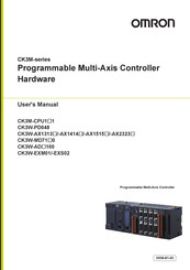
Omron CK3W-MD71 0 Series User Manual (218 pages)
Programmable Multi-Axis Controller Hardware
Brand:
Omron
| Category:
Controller
| Size: 7.87 MB
Table of Contents
Introduction
3
Intended Audience
3
Applicable Products
3
Manual Structure
4
Page Structure
4
Special Information
5
Sections in this Manual
7
Wiring 7
7
Table of Contents
8
Terms and Conditions Agreement
12
Warranty, Limitations of Liability
12
Application Considerations
13
Disclaimers
13
Safety Precautions
15
Definition of Precautionary Information
15
Symbols
15
Warning
16
Cautions
18
Precautions for Safe Use
19
Precautions for Correct Use
24
Regulations and Standards
26
Conformance to EU Directives
26
Condition for Compliance with EU Directives
27
Conformance to UL and CSA Standards
27
Conformance to KC Certification
27
Versions
28
Checking Versions
28
Related Manuals
29
Terminology
30
Revision History
31
Introduction to Motion Controllers
33
Features and System Configuration
34
Motion Controller Features
34
Introduction to the System Configurations
34
Support Software
36
CK3M-Series Operating Procedure
37
System Configuration
39
Basic Configuration
40
CK3W Unit Configuration
40
Ethercat Network Configuration
40
Ethercat Network Configuration
41
Connecting to the Power PMAC IDE
43
Ethernet Network Configuration
44
Configuration Units
45
Section 3 Configuration Units
47
CPU Unit
47
Models and Specifications
47
Part Names and Functions
49
Operation Status Indicators
50
Watchdog Output Terminal Block
51
USB Memory Device
52
Power Supply Unit
54
Models and Specifications
54
Part Names and Functions
55
Axis Interface Unit
56
Models and Specifications
56
Part Names and Functions
58
Operation Status Indicators
59
Address Switch Setting
60
Encoder Connector Specifications
60
Encoder Loss Detection
65
Pulse Input Timing Specifications for Digital Quadrature Encoder
66
Input Specifications for Sinusoidal Encoder
68
Outflag Function
70
Amplifier Connector Specifications
71
DA Output Method
74
Directpwm Output Method
75
Flag Connection Terminal Block Specifications
76
General Digital I/O Connection Terminal Block Specifications
80
Digital I/O Unit
87
Models and Specifications
87
Part Names and Functions
91
Operation Indicators
92
Address Switch Setting
92
Terminal Arrangement
93
I/O Data
94
Analog Input Unit
96
Models and Specifications
96
Part Names and Functions
97
Operation Indicators
98
Address Switch Setting
98
Terminal Arrangement
99
Analog Input Data
100
Input Filter
101
Expansion Master Unit and Expansion Slave Unit
103
Models and Specifications
103
Part Names and Functions
104
Operation Indicators
104
System Configuration
104
Installation
107
Section 4 Installation
108
Processing at Power on and Power off
108
Power on Operation
108
Power off Operation
108
Fail-Safe Circuits
110
Mounting Units
111
Installation in a Control Panel
111
Connecting Adjacent Units
115
Mounting to DIN Track
116
DIN Track and Accessories
118
Assembled Appearance and Dimensions
119
Control Panel Installation
123
Temperature
123
Humidity
124
Vibration and Shock
125
Atmosphere
125
Electrical Environment
125
Grounding
130
Power Supply Wiring
136
Power Supply Unit CK3W-PD048
136
Power Supply Used
136
Applicable Wires
136
Grounding
137
Required Tools
138
Connecting Ferrules
138
Connecting Twisted Wires/Solid Wires
138
Removing Wires
139
CPU Unit Wiring
141
Laying the Ethercat Network
141
Laying the Ethernet Network
146
Watchdog Timer Output Wiring
149
USB Memory Device Connection
151
Axis Interface Unit Wiring
152
Encoder Connector Wiring
152
Amplifier Connector Wiring
158
Flag Terminal Block/General I/O Terminal Block Wiring
160
Digital I/O Unit Wiring
167
Wiring the Terminals
167
Precautions When Connecting a Two-Wire DC Sensor
170
Precautions When Connecting to Digital Output
172
Analog Input Unit Wiring
174
Wiring the Terminals
174
Expansion Master Unit and Expansion Slave Unit Wiring
178
Troubleshooting
179
Types of Errors
180
Using the Indicators to Check Errors
181
Indicator Types
181
Procedure for Identifying Errors
181
Troubleshooting for Errors
183
Fatal Errors in the CPU Unit
183
Non-Fatal Errors in the CPU Unit
184
Initialization of CPU Unit Using USB Memory
186
Sys.status Register
187
Sys.status Register List
187
Details of Flags
187
Inspection and Maintenance
197
Section 7 Inspection and Maintenance
198
Cleaning and Maintenance
198
Cleaning
198
Periodic Inspections
198
Maintenance Procedures
200
Unit Replacement Precautions
200
Backup
200
Unit Replacement
200
Appendices
203
A-1 General Specifications
204
A-2 Dimensions
205
A-2-1 CPU Unit
205
CPU Unit
205
A-2-2 Power Supply Unit
206
A-2-3 Axis Interface Unit
206
A-2-4 CK3W-MD and CK3W-AD Units
207
A-2-5 Expansion Master Unit and Expansion Slave Unit
208
A-2-6 End Cover
209
Restrictions on Using the NX-Series Ethercat Coupler Unit
210
OMRON Servo Drive Connection Example
211
A-5 Version Information
212
A-6 How to Read the Lot Number
213
Index
215
Advertisement
Omron CK3W-MD71 0 Series Quick Start Manual (12 pages)
Digital I/O units for CK3M Controller
Brand:
Omron
| Category:
I/O Systems
| Size: 2.44 MB
Table of Contents
Basic System Configuration
2
Ethercat Network Configuration
3
Ordering Information
4
Digital I/O Units
4
General Specifications
4
Specifications
5
Part Names and Functions
8
Applicable Wires
9
Required Tools
9
Related Manuals
10
Advertisement
Related Products
Omron CK3W-MD7110
Omron CK3W-MD7120
Omron CK3W-PD048
Omron CK3W-AX1313N
Omron CK3W-AX1414N
Omron CK3W-AX2323N
Omron CK3W-GC 00 Series
Omron CK3W-GC1100
Omron CK3W-GC2100
Omron CK3W-AD3100
Omron Categories
Blood Pressure Monitor
Controller
Accessories
Switch
Inverter
More Omron Manuals
Login
Sign In
OR
Sign in with Facebook
Sign in with Google
Upload manual
Upload from disk
Upload from URL