Omron 3G3RX-A4007-V1 Manuals
Manuals and User Guides for Omron 3G3RX-A4007-V1. We have 2 Omron 3G3RX-A4007-V1 manuals available for free PDF download: User Manual, Instruction Manual
Omron 3G3RX-A4007-V1 User Manual (688 pages)
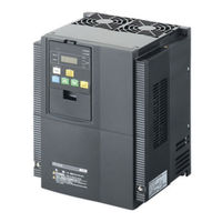
High-function General-purpose Inverter
Table of Contents
Advertisement
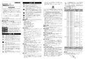
Omron 3G3RX-A4007-V1 Instruction Manual (4 pages)
3G3RX-*-V1 High-function General-purpose Inverter
Advertisement