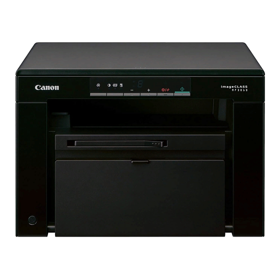

Related Manuals for Canon M3010 Series


Summary of Contents for Canon M3010 Series
-
Page 1: Service Manual
M3010 Series Service Manual Product Overview Technical Overview Periodical Services Disassembly/Assembly Adjustment Trouble Shooting Error Codes Service Mode Appendix... - Page 2 This manual is copyrighted with all rights reserved. Under the copyright laws, this manual may changes in the contents of this manual over a long or short period, Canon will issue a new not be copied, reproduced or translated into another language, in whole or in part, without the edition of this manual.
- Page 3 Explanation of Symbols The following rules apply throughout this Service Manual: The following symbols are used throughout this Service Manual. 1. Each chapter contains sections explaining the purpose of specific functions and the relationship between electrical and mechanical systems with reference to the timing of Symbols Explanation Symbols...
-
Page 4: Table Of Contents
Contents Safety Precautions Print Sequence ------------------------------------------------------------------------------ 2-3 Power-On Sequence----------------------------------------------------------------------- 2-4 CDRH Provisions -------------------------------------------------------------0-2 Controller System -------------------------------------------------------------2-5 Laser Safety --------------------------------------------------------------------0-2 Main Controller --------------------------------------------------------------------- 2-5 About Laser Beams --------------------------------------------------------------- 0-2 Overview -------------------------------------------------------------------------------------- 2-5 Handling Laser Scanner Unit --------------------------------------------------- 0-2 Engine Controller ------------------------------------------------------------------ 2-5 Toner Safety --------------------------------------------------------------------0-3 General description ------------------------------------------------------------------------ 2-5 About Toner ------------------------------------------------------------------------- 0-3... - Page 5 Image Formation System ------------------------------------------------- 2-13 Jam Detection Outline --------------------------------------------------------------------2-25 Delay Jam -----------------------------------------------------------------------------------2-25 Overview/Configuration ---------------------------------------------------------2-13 Stationary Jam -----------------------------------------------------------------------------2-27 Overview -------------------------------------------------------------------------------------2-13 Other Jams ----------------------------------------------------------------------------------2-27 Print Process --------------------------------------------------------------------------------2-13 Service Works ---------------------------------------------------------------------2-28 Static Latent Image Formation Block -------------------------------------------------2-14 At parts replacement ----------------------------------------------------------------------2-28 Development Block------------------------------------------------------------------------2-14 Maintenance --------------------------------------------------------------------------------2-28 Transfer Block ------------------------------------------------------------------------------2-15 Notes on service works ------------------------------------------------------------------2-28...
- Page 6 Motor ------------------------------------------------------------------------------------------- 4-5 Preparation ----------------------------------------------------------------------------------4-26 Solenoid --------------------------------------------------------------------------------------- 4-6 Procedure ------------------------------------------------------------------------------------4-26 Sensor ----------------------------------------------------------------------------------------- 4-6 Controller System ----------------------------------------------------------- 4-28 Switch ------------------------------------------------------------------------------------------ 4-7 Layout Drawing --------------------------------------------------------------------4-28 Heater/Thermistor/Thermoswitch/ ------------------------------------------------------ 4-7 Removing the Control Panel Unit ---------------------------------------------4-29 PCB -------------------------------------------------------------------------------------------- 4-8 Removing the Drive Belt --------------------------------------------------------4-29 List of Connectors -------------------------------------------------------------4-9 Preparation ----------------------------------------------------------------------------------4-29 Reader Unit -------------------------------------------------------------------------- 4-9...
- Page 7 Pickup Feed System ------------------------------------------------------- 4-51 Entering Service Mode ----------------------------------------------------------- 8-2 Layout Drawing --------------------------------------------------------------------4-51 Exiting Service Mode ------------------------------------------------------------- 8-2 Removing the Pickup Unit ------------------------------------------------------4-51 Screen Operation in Service Mode -------------------------------------------- 8-3 Preparation ----------------------------------------------------------------------------------4-51 COPIER -------------------------------------------------------------------------8-4 Procedure ------------------------------------------------------------------------------------4-51 DISPLAY ----------------------------------------------------------------------------- 8-4 Removing the Pickup Roller ----------------------------------------------------4-54 ADJUST ------------------------------------------------------------------------------ 8-5 Removing the Pickup Solenoid ------------------------------------------------4-55 FUNCTION -------------------------------------------------------------------------- 8-7...
-
Page 8: Safety Precautions
Safety Precautions ■ CDRH Provisions ■ Laser Safety ■ Toner Safety ■ Notes on Handling M3010 Series Lithium Battery ■ Notes on Assembly/ Disassembly... -
Page 9: About Laser Beams
CDRH Provisions Laser Safety Food and Drug CDRH (Center for Devices and Radiological Health) under FDA (Food and About Laser Beams Drug Administration) enforced provisions of the section for laser and laser products on August 2, 1976. These provisions are applicable to all laser products manufactured or assembled Laser radiation may be hazardous to human. -
Page 10: Toner Safety
Toner Safety Notes on Assembly/Disassembly Follow the items below to assemble/disassemble the device. About Toner 1. Disconnect the power plug to avoid any potential dangers during assembling/disassembling works. Toner is a non-toxic material composed of plastic, iron, small amount of pigment, etc. 2. -
Page 11: Product Overview
Product Overview ■ Product Lineup ■ Product Features ■ Specifications ■ Parts Name Product Overview... -
Page 12: Host Machine
Product Overview > Product Features > Product Features Product Lineup Product Features Host Machine Product Features 1. Compact/high-speed printer Model name MF3010 This machine is a high-speed B&W printer with a compact body design and the print speed Configuration 3in1 single-sided platen of 19 ppm (LTR). -
Page 13: Specifications
Product Overview > Specifications > Product Specifications Specifications Environment temperature range 10 to 30 degrees Centigrade Environment humidity range 20 to 80 % Duplex method None Product Specifications Host Interface Standard: USB/Hi-speed USB, Options: None Hard disk capacity Standard: None, Options: None Memory capacity Standard: 64 MB, Options: None Copyboard... -
Page 14: Parts Name
Product Overview > Parts Name > External View > Rear side of the machine Parts Name ■ Rear side of the machine External View ■ Front side of the machine [12] [13] [11] [10] F-1-2 Name Name Copyboard Cover Left Cover F-1-1 Copyboard Glass USB Device Port... -
Page 15: Cross Section View
Product Overview > Parts Name > Control Panel Cross Section View Control Panel [11] [10] [12] F-1-4 Name Function [1] Menu setting lamp (green) Blinking: Menu is being set. F-1-3 Menu setting key Menu setting mode is entered. Name Name Pressing this key while menu is being set returns to one layer Copyboard Glass Photosensitive Drum... -
Page 16: Technical Overview
Technical Overview ■ Basic Configuration ■ Controller System ■ Original Exposure System ■ Laser Exposure System ■ Image Formation System ■ Fixing System ■ Pickup Feed System ■ External And Controls System Technical Overview... -
Page 17: Configuration Function
Technical Overview > Basic Configuration > Basic Sequence > Basic Sequence of Operation Basic Configuration Basic Sequence ■ Basic Sequence of Operation Configuration function The engine controller controls the operation sequence. The following table provides an outline The machine may be broadly divided into the following 7 functional blocks: engine control of machine operation occurring from when the power switch is turned on to when printing system,original exposure system, laser exposure system, image formation system, pickup ends and Main Motor (M1) stop, indicating the purposes of intervals and engine operation. -
Page 18: Print Sequence
Technical Overview > Basic Configuration > Basic Sequence > Print Sequence ■ Print Sequence Start KEY Power-on (Unit:Seconds) WAIT STBY INTR PRINT LSTR STBY Sequence Reader Motor (M3) CIS Unit Controls at 80 C Print temperature control Fixing heater Relay Waiting for Print command Print command... -
Page 19: Power-On Sequence
Technical Overview > Basic Configuration > Basic Sequence > Power-On Sequence ■ Power-On Sequence The sequences from the power-ON to the STBY period are described below. 1) Power-ON. 2) CPU initialization. 3) Video interface communication start. 4) Residual paper check. Detecting paper presence by each sensor signaling. -
Page 20: Controller System
Technical Overview > Controller System > Engine Controller > General description Controller System Engine Controller ■ General description Main Controller Engine controller is the circuit to control the operation sequence of the host machine and it is ■ Overview controlled by the CPU inside the engine controller. When the Power Switch (SW1100) is turned ON and DC power is supplied through the low The Main Controller receives print information from the Reader and external equipment voltage power inside engine controller, CPU starts the printer operation control. -
Page 21: Service Works
Technical Overview > Controller System > Service Works > Notes on service works Service Works ■ At parts replacement No work is required for this product at parts replacement. ■ Maintenance No periodically replaced parts, durable parts or periodical service is set for this product. ■... -
Page 22: Original Exposure System
Technical Overview > Original Exposure System > Major Components Original Exposure System Major Components Followings are the major components for Document Exposure System. Overview • The CIS Unit to scan document • The Reader motor, the drive pulley, the drive belt, to shift the CIS Unit item function / method In image scanning control, the CIS Unit is shifted by rotating the Reader motor based on the... -
Page 23: Service Works
Technical Overview > Original Exposure System > Service Works > Notes on service works Service Works ■ At parts replacement No work is required for this product at parts replacement. ■ Maintenance No periodically replaced parts, durable parts or periodical service is set for this product. ■... -
Page 24: Laser Exposure System
Technical Overview > Laser Exposure System > Overview > Overview Laser Exposure System The operational sequence of the laser scanner unit is described below. 1) When the Main controller sends print instruction command, the Engine controller rotates the Four-faced mirror, causing the Scanner Motor (M2) to rotate. Overview 2) When the Scanner Motor (M2) starts to rotate, the Engine controller emits the laser forcibly ■... -
Page 25: Controlling The Laser Activation Timing
Technical Overview > Laser Exposure System > Controlling the Laser Activation Timing > Horizontal Sync Control 2-10 Controlling the Laser Activation Timing The engine controller sends the laser control signals (CNT0, CNT1) for changing the operation mode of the laser to the logic circuit in the laser driver IC, as well as the video ■... -
Page 26: Laser Control
Technical Overview > Laser Exposure System > Laser Scanner Motor Control > Overview 2-11 Laser Control Laser Scanner Motor Control ■ Auto Power Control (APC) ■ Overview This is the control to emit a constant level of laser diode. This is the control to rotate the Scanner Motor (M2) at a constant speed to emit the laser There are two types of APC;... -
Page 27: Scanner Motor Fault Detection
Technical Overview > Laser Exposure System > Service Works > Notes on service works 2-12 Service Works ■ Scanner Motor Fault Detection This is the detection of faults in the laser scanner unit. ■ At parts replacement When the laser scanner unit falls into either of the following status, the engine controller No work is required for this product at parts replacement. -
Page 28: Image Formation System
Technical Overview > Image Formation System > Overview/Configuration > Print Process 2-13 Image Formation System ■ Print Process This explains the basic process of the operations that a printer executes for image formation. Overview/Configuration The print process of this equipment is divided largely into 5 blocks, 7 steps. Toner images are formed on papers by executing the steps of each block in order. -
Page 29: Static Latent Image Formation Block
Technical Overview > Image Formation System > Overview/Configuration > Development Block 2-14 ■ Static Latent Image Formation Block Step 2: Laser beam exposure In this step, static latent images are formed on the photosensitive drum with laser beam. This block is comprised of two steps and forms static latent images on the photosensitive When laser beams are scanned on the photosensitive drum negatively charged, bright areas drum. -
Page 30: Transfer Block
Technical Overview > Image Formation System > Overview/Configuration > Drum Cleaning Block 2-15 ■ Transfer Block ■ Fixing Block This block is comprised of two steps; it transfers toner images on the surface of the This block applies pressure and heat to papers and the toner on them to fix toner images to photosensitive drum to papers. -
Page 31: High-Voltage Control
Technical Overview > Image Formation System > High-Voltage Control > Generating Transfer Bias 2-16 High-Voltage Control ■ Generating Developing Bias The developing bias is a DC negative bias that is output to affix toner to the static latent ■ Overview images formed on the photosensitive drum. -
Page 32: Toner Cartridge
Technical Overview > Image Formation System > Toner Cartridge > Toner Cartridge Absence/Presence Detection 2-17 Toner Cartridge The Paper Leading Edge Sensor (PS751) performs both this detection and paper feed detection. Therefore, the engine controller cannot make a judgment of ‘Toner cartridge ■... -
Page 33: Service Works
Technical Overview > Image Formation System > Service Works > Notes on service works 2-18 Service Works ■ At parts replacement No work is required for this product at parts replacement. ■ Maintenance No periodically replaced parts, durable parts or periodical service is set for this product. ■... -
Page 34: Fixing System
Technical Overview > Fixing System > Overview/Configuration > Main Parts of Fixing assembly 2-19 Fixing System ■ Main Parts of Fixing assembly Engine controller Overview/Configuration Fixing control FIXING HEATER ■ Overview DRIVE signal Fixing/delivery system consists of the fixing film unit, pressure roller and delivery roller etc. Fixing heater These rollers are driven by the Main Motor (M1). -
Page 35: Various Control Mechanisms
Technical Overview > Fixing System > Various Control Mechanisms > Protective Functions 2-20 Various Control Mechanisms Fixing target temperature varies according to the fixing mode, and there are 8 types of the mode. ■ Fixing Temperature Control These modes are determined according to the paper type settings and resolution settings (see the caution) in a driver. -
Page 36: Failure Detection
Technical Overview > Fixing System > Various Control Mechanisms > Protective Functions 2-21 2) Protection function by fixing heater safety circuit 6) Startup failure detection Fixing Heater (H1) safety circuit monitors the Thermistor (TH1) temperature consistently. If temperature of the Fixing Assembly is 100 deg C or higher when the machine becomes in When Thermistor (TH1) reaches approx 235 deg C, it determines that the Fixing Heater (H1) pickup enabled state after entering fixing low voltage inlet sequence, it is judged as startup is overheating and the fixing heater safety circuit turns OFF the relay drive circuit to shut... -
Page 37: Other Functions
Technical Overview > Fixing System > Other Functions > Throughput Down Control 2-22 ● Processing after failure detection ● Throughput Down at Initial Rotation If the Main Motor is in driving state when Fixing Assembly failure is detected, rotation of the The time for initial rotation is extended according to the fixing mode. -
Page 38: Service Works
Technical Overview > Fixing System > Service Works > Notes on service works 2-23 Service Works ● Throughput Down Between Sheets Throughput down control is performed according to fixing mode, special mode, resolution, ■ At parts replacement and actual fed paper size. Actual fed paper size No work is required for this product at parts replacement. -
Page 39: Pickup Feed System
Technical Overview > Pickup Feed System > Overview > Overview 2-24 Pickup Feed System The pickup and feeding system executes pickup and feeding of papers and is composed of the Main Motor (M1), Pickup Solenoid (SL1), and rollers. In this equipment, pickup from the pickup tray is available. There is only a face-down delivery. Overview Papers set on the pickup tray are fed by the pickup roller. -
Page 40: Detecting Jams
Technical Overview > Pickup Feed System > Detecting Jams > Delay Jam 2-25 Detecting Jams ■ Delay Jam ● Delivery Delay Jam ■ Jam Detection Outline There are 3 cases of delivery delay jam detection. ● Overview A. No preceding sheet The following sensors are installed to detect absence/presence of papers and whether papers B. - Page 41 Technical Overview > Pickup Feed System > Detecting Jams > Delay Jam 2-26 B. Preceding sheet exists 1 ● Delivery Delay Jam during Auto Delivery When the Paper Leading Edge Sensor (PS751) detects presence of paper and the Fixing Paper Leading Edge Delivery Sensor (PS701) detects absence of paper at 1490 (2235) msec.
-
Page 42: Stationary Jam
Technical Overview > Pickup Feed System > Detecting Jams > Other Jams 2-27 ■ Stationary Jam ● Delivery Stationary Jam during Auto Delivery When the Paper Leading Edge Sensor (PS751) detects absence of paper at 1490 (2235) ● Pickup Stationary Jam msec. -
Page 43: Service Works
Technical Overview > Pickup Feed System > Service Works > Notes on service works 2-28 Service Works ● Initial Paper Presence Jam when Printing When the Fixing Delivery Sensor (PS701) or the Paper Width Sensor (PS702) detects ■ At parts replacement presence of paper immediately before the Main Motor (M1) starts rotating, it is judged as a delivery stationary jam. -
Page 44: External And Controls System
Technical Overview > External And Controls System > Power Supply > Protective Functions 2-29 External And Controls System ■ Protective Functions ● Power protective function Power Supply Low voltage power circuit carries the overcurrent preventive function against and overvoltage preventive function that block the voltage output automatically to prevent the power circuit ■... -
Page 45: Service Works
Technical Overview > External And Controls System > Service Works > Notes on service works 2-30 Service Works ■ At parts replacement No work is required for this product at parts replacement. ■ Maintenance No periodically replaced parts, durable parts or periodical service is set for this product. ■... -
Page 46: Periodical Services
Periodical Services ■ Periodically Replaced Parts ■ Consumables ■ Periodical Service ■ Cleaning Periodical Services... - Page 47 Periodical Services > Consumables > Consumables Periodically Replaced Parts Consumables Periodically Replaced Parts Consumables There is no periodically replaced part with this machine. There is no consumable with this machine. Periodical Services > Consumables > Consumables...
-
Page 48: Periodical Service
Periodical Services > Cleaning Periodical Service Cleaning Scheduled Servicing There is no portion that requires schedule servicing in this equipment. F-3-1 Cleaning parts Procedure [1] Fixing inlet guide Clean it with a dry lint-free paper. [2] Static eliminator Clean it with a dry lint-free paper. [3] Transfer Roller Basically, do not touch it with your hands or clean it. -
Page 49: Disassembly/Assembly
Disassembly/Assembly ■ List Of Parts ■ List of Connectors ■ External Cover / Interior System ■ Original Exposure System ■ Controller System ■ Laser Exposure System ■ Image Formation System ■ Fixing System ■ Pickup Feed System Disassembly/Assembly... - Page 50 Disassembly/Assembly > Outline Outline This chapter describes disassembling/assembling procedure of this equipment. The service technician is to identify the cause of the failures according to "Chapter 6 Troubleshooting" and to replace the faulty parts by following the disassembling procedure. In addition, replace the consumable parts by following the same disassembling procedure.
-
Page 51: External View
Disassembly/Assembly > List Of Parts > External View > Rear Side List Of Parts ■ Rear Side External View ■ Front Side [11] [10] F-4-2 Name Reference F-4-1 Copyboard Cover (Refer to page 4-19) Name Reference Copyboard Glass (Refer to page 4-21) Control Panel Unit (Refer to page 4-29) Copyboard Upper Cover... -
Page 52: List Of Main Unit
Disassembly/Assembly > List Of Parts > List of Main Unit > Printer Unit List of Main Unit ■ Printer Unit ■ Reader Unit F-4-4 F-4-3 Name Reference Name Reference Fixing Assembly (Refer to page 4-46) Copyboard Cover (Refer to page 4-19) Main Drive Unit (Refer to page 4-29) Control Panel Unit... -
Page 53: Electrical Components
Disassembly/Assembly > List Of Parts > Electrical Components > Motor Electrical Components ■ Motor ■ Reader Unit F-4-5 Name Main Unit Reference Adjastment during parts replacement F-4-6 Reader Motor Reader Unit (Refer to page 4-23) - Name Main Unit Reference Adjastment during CIS CIS Unit Reader Unit (Refer to page 4-26) -... -
Page 54: Solenoid
Disassembly/Assembly > List Of Parts > Electrical Components > Sensor ■ Solenoid ■ Sensor PS701 PS702 PS751 PS901 F-4-7 F-4-8 Name Main Unit Reference Adjastment during Name Main Unit Reference Adjastment during parts replacement parts replacement SL1 Pickup Solenoid Pickup Unit (Refer to page PS901 Motor Encoder Sensor Main Unit... -
Page 55: Switch
Disassembly/Assembly > List Of Parts > Electrical Components > Heater/Thermistor/Thermoswitch/ ■ Switch ■ Heater/Thermistor/Thermoswitch/ SW501 SW1100 F-4-10 F-4-9 Name Main Unit Reference Adjastment during Name Main Unit Reference Adjastment during parts replacement parts replacement Temperature fuse Fixing Assembly SW1100 Power Switch Main Unit Fixing Heater Fixing Assembly... -
Page 56: Pcb
Disassembly/Assembly > List Of Parts > Electrical Components > PCB ■ PCB F-4-11 Name Main Unit Reference Adjastment during parts replacement [1] Control Panel PCB Control Panel Unit (Refer to page 4-29) - [2] Motor Driver PCB Main Unit [3] Laser Driver PCB Laser Scanner Unit - [4] Engine Controller PCB Main Unit... -
Page 57: List Of Connectors
Disassembly/Assembly > List of Connectors > Reader Unit List of Connectors Reader Unit F-4-12 J No. Symbol Name Relay Connector J No. Symbol Name REMARKS Main Controller PCB CIS Unit Main Controller PCB Reader Motor T-4-12 Disassembly/Assembly > List of Connectors > Reader Unit... -
Page 58: Printer Unit
Disassembly/Assembly > List of Connectors > Printer Unit 4-10 Printer Unit J702 J702 J562 J551 J552 J101 J562 J551 J101 J571 J801 F-4-13 J552 J571 J542 J No. Symbol Name Relay Connector J No. Symbol Name REMARKS J571 Engine Controller PCB J571 Motor Driver PCB Motor Driver PCB... - Page 59 Disassembly/Assembly > List of Connectors > Printer Unit 4-11 J923 J923 J401 J902 J581 J581 J912 J912 F-4-14 J No. Symbol Name Relay Connector J No. Symbol Name REMARKS J923 Motor Driver PCB J923 Main Motor J581 Engine Controller PCB J581 Memory Tag J902...
-
Page 60: External Cover / Interior System
Disassembly/Assembly > External Cover / Interior System > Layout Drawing > Rear Side 4-12 External Cover / Interior System ■ Rear Side Layout Drawing ■ Front Side [11] [10] F-4-16 Name Reference F-4-15 Copyboard Cover (Refer to page 4-19) Name Reference Copyboard Glass (Refer to page 4-21) -
Page 61: Removing The Left Cover
Disassembly/Assembly > External Cover / Interior System > Removing the Left Cover 4-13 Removing the Left Cover 2) Release the 2 claws [1] at the rear side and the claw [2] at the lower side. NOTE: The following shows the 5 claws [1] and 2 hooks [2] of the Left Cover. F-4-19 3) Open the Reader Unit, and release the 2 claws [1] at the upper side. -
Page 62: Removing The Right Cover
Disassembly/Assembly > External Cover / Interior System > Removing the Right Cover 4-14 Removing the Right Cover 2) Release the 2 claws [1] at the rear side and the claw [2] at the lower side. NOTE: The following shows the 5 claws [1] and 2 hooks [2] of the Right Cover. F-4-23 3) Open the Reader Unit, and release the 2 claws [1] at the upper side. -
Page 63: Removing The Front Cover Unit
Disassembly/Assembly > External Cover / Interior System > Removing the Upper Cover > Procedure 4-15 Removing the Front Cover Unit Removing the Upper Cover ■ Preparation ■ Preparation 1) Remove the Left Cover.(Refer to page 4-13) 1) Remove the Left Cover.(Refer to page 4-13) 2) Remove the Right Cover.(Refer to page 4-14) 2) Remove the Reader Unit.(Refer to page 4-20) 3) Remove the Right Cover.(Refer to page 4-14) - Page 64 Disassembly/Assembly > External Cover / Interior System > Removing the Upper Cover > Procedure 4-16 4) Remove the Delivery Tray [1]. 6) Remove the Upper Cover [1]. • 6 Screws (black TP) [2] F-4-27 5) Remove the Arm Shaft Rail Holder [1] of the Reader Unit. F-4-29 •...
-
Page 65: Removing The Rear Cover
Disassembly/Assembly > External Cover / Interior System > Removing the Rear Cover > Procedure 4-17 Removing the Rear Cover CAUTION: ■ Preparation Be sure to install the 2 Fixing Pressure Arms [2] and the Cartridge Arm [3] to the Delivery Tray [1] when assembling. 1) Remove the Left Cover.(Refer to page 4-13) 2) Remove the Right Cover.(Refer to page 4-14) ■... - Page 66 Disassembly/Assembly > External Cover / Interior System > Removing the Rear Cover > Procedure 4-18 2) Remove the Rear Cover [1]. • 2 Claws [2] • 2 Hooks [3] F-4-32 4-18 Disassembly/Assembly > External Cover / Interior System > Removing the Rear Cover > Procedure...
-
Page 67: Original Exposure System
Disassembly/Assembly > Original Exposure System > Removing the Copyboard Cover. 4-19 Original Exposure System Removing the Copyboard Cover. 1) Remove the Copyboard Cover [1]. Layout Drawing • 4 Shafts [2] F-4-34 F-4-33 Name Main Unit Reference Adjastment during Remarks parts replacement Copyboard Cover Reader Unit (Refer to page 4-19) - Reader Unit... -
Page 68: Removing The Reader Unit
Disassembly/Assembly > Original Exposure System > Removing the Reader Unit > Procedure 4-20 Removing the Reader Unit 4) Remove the Arm Shaft [1] of the Reader Unit, and lift the arm [2] of the Reader Unit. ■ Preparation 1) Remove the Left Cover.(Refer to page 4-13) ■... -
Page 69: Removing The Copyboard Glass Unit
Disassembly/Assembly > Original Exposure System > Removing the Copyboard Glass Unit > Procedure 4-21 Removing the Copyboard Glass Unit 5) Remove the Reader Unit [1]. • 2 Shafts [2] ■ Preparation 1) Remove the Control Panel Unit.(Refer to page 4-29) ■... - Page 70 Disassembly/Assembly > Original Exposure System > Removing the Copyboard Glass Unit > Procedure 4-22 2) Remove the Copyboard Glass Unit [1]. NOTE: • 6 Claws [2] The following shows the 6 claws [3] of the Copyboard Glass Unit. CAUTION: • Be sure not to lose the 2 spacers [1] of the CIS Unit when disassembling/ assembling.
-
Page 71: Removing The Reader Motor Unit
Disassembly/Assembly > Original Exposure System > Removing the Reader Motor Unit > Procedure 4-23 Removing the Reader Motor Unit ■ Procedure ■ Preparation CAUTION: 1) Remove the Left Cover.(Refer to page 4-13) • Be sure not to lose the 2 spacers [1] of the CIS Unit when disassembling/ 2) Remove the Reader Unit.(Refer to page 4-20) assembling. - Page 72 Disassembly/Assembly > Original Exposure System > Removing the Reader Motor Unit > Procedure 4-24 2) Move the gear [1] on the right side, and remove the belt [3] from the gear [2] on the left CAUTION: side. Grease is applied on the shaft [1] of the CIS Unit, so be careful not to let the belt [2] come in contact with the shaft.
- Page 73 Disassembly/Assembly > Original Exposure System > Removing the Reader Motor Unit > Procedure 4-25 4) Remove the Reader Motor Unit [1]. CAUTION: • 2 Screws [2] • 1 Grounding Plate [3] If the CIS Unit comes off, be sure to align the tooth [1] on the belt with the tooth [2] on the bottom of the CIS Unit to install the unit.
-
Page 74: Removing The Cis Unit
Disassembly/Assembly > Original Exposure System > Removing the CIS Unit > Procedure 4-26 Removing the CIS Unit 1) Move the CIS Unit [1]. ■ Preparation 1) Remove the Control Panel Unit.(Refer to page 4-29) 2) Remove the Copyboard Glass Unit.(Refer to page 4-21) ■... - Page 75 Disassembly/Assembly > Original Exposure System > Removing the CIS Unit > Procedure 4-27 4) Remove the CIS Unit [3]. CAUTION: • 2 Shafts [2] • At installation, be sure to put the Flat Cable [1] through the hole [A] of the CIS Unit CAUTION: Base and connect the cable to the CIS Unit [2].
-
Page 76: Controller System
Disassembly/Assembly > Controller System > Layout Drawing 4-28 Controller System Name Main Unit Reference Adjastment during Remarks parts replacement [1] Control Panel Unit Main Unit (Refer to page Layout Drawing 4-29) [2] Control Panel PCB Control Panel Unit [3] Main Motor Main Unit (Refer to page 4-31) -
Page 77: Removing The Control Panel Unit
Disassembly/Assembly > Controller System > Removing the Drive Belt > Procedure 4-29 Removing the Control Panel Unit Removing the Drive Belt ■ Preparation 1) Open the Reader Unit [1], and remove the 2 screws [2]. 1) Remove the Right Cover.(Refer to page 4-14) ■... - Page 78 Disassembly/Assembly > Controller System > Removing the Drive Belt > Procedure 4-30 3) Remove the Drive Cover [1]. 5) Remove the Drive Belt [1]. • 4 Screws [2] CAUTION: When removing the Drive Cover [1], be sure to slowly remove it directly upward so as not to shift the phase of the gears.
-
Page 79: Removing The Main Motor
Disassembly/Assembly > Controller System > Removing the Main Motor > Procedure 4-31 Removing the Main Motor CAUTION: ■ Preparation When installing the Drive Cover [2], be sure to align the 7 shafts with the shaft holes [1] to fit the cover in place. 1) Remove the Left Cover.(Refer to page 4-13) 2) Remove the Reader Unit.(Refer to page 4-20) 3) Remove the Right Cover.(Refer to page 4-14) - Page 80 Disassembly/Assembly > Controller System > Removing the Main Motor > Procedure 4-32 2) Remove the Motor Driver PCB [1]. 5) Remove the Tension Unit [1]. • 2 Connectors [2] • 1 Screw [2] • 2 Claws [3] F-4-72 F-4-74 3) Free the Motor Harness [1] from the Harness Guide [A]. 6) Remove the Main Motor [1].
- Page 81 Disassembly/Assembly > Controller System > Removing the Main Motor > Procedure 4-33 CAUTION: CAUTION: When installing the Main Motor, be sure to install the harness [1] to the upper side of • When installing the Scanner Cover, be sure to pass the Shutter Open/Close Lever [1] through the hole [A] in the Scanner Cover.
-
Page 82: Removing The Main Controller Pcb
Disassembly/Assembly > Controller System > Removing the Main Controller PCB > After Replacing the Main Controller PCB 4-34 Removing the Main Controller PCB ■ After Replacing the Main Controller PCB After replacing the PCB, be sure to execute "Country Code" of the country selection mode ■... -
Page 83: Removing The Engine Controller Pcb
Disassembly/Assembly > Controller System > Removing the Engine Controller PCB > Procedure 4-35 Removing the Engine Controller PCB 3) Remove the Main Controller PCB Installation Plate [1]. • 1 Screw (with washer) [2] ■ Preparation • 2 Screws (black TP) [3] •... - Page 84 Disassembly/Assembly > Controller System > Removing the Engine Controller PCB > Procedure 4-36 6) Disconnect the 3 Flat Cables [1] and 6 connectors [2], and free the harness from the guide 7) Remove the Engine Controller PCB [1]. [A]. • 4 Screws (with washer) [2] •...
- Page 85 Disassembly/Assembly > Controller System > Removing the Engine Controller PCB > Procedure 4-37 CAUTION: CAUTION: When installing, be sure to install the Engine Controller PCB before installing the Be sure that the Switchboard [1] moves upward and downward. Switchboard [2] to the lower side of the Switch Flag [1]. F-4-88 CAUTION: When installing the terminal [1], be sure that the Contact Spring [2] is in contact with it.
-
Page 86: Removing The Paper Leading Edge Sensor
Disassembly/Assembly > Controller System > Removing the Paper Leading Edge Sensor > Procedure 4-38 Removing the Paper Leading Edge Sensor 2) Remove the terminal [1], and free the harness [2] from the Harness Guide [A]. 3) Remove the Harness Retaining Spring [3] from the 2 hooks [B]. ■... - Page 87 Disassembly/Assembly > Controller System > Removing the Paper Leading Edge Sensor > Procedure 4-39 5) Free the harness [1] from the Harness Guide [A], and remove the Paper Leading Edge CAUTION: Sensor [2]. • 2 Claws [3] When installing the terminal [1], be sure that the Contact Spring [2] is in contact with it. F-4-93 F-4-95 NOTE:...
-
Page 88: Removing The Fixing Delivery/Paper Width Sensor Pcb
Disassembly/Assembly > Controller System > Removing the Fixing Delivery/Paper Width Sensor PCB > Procedure 4-40 Removing the Fixing Delivery/Paper Width Sensor PCB 2) Remove the terminal [1], and free the harness [2] from the Harness Guide [A]. 3) Remove the Harness Retaining Spring [3] from the 2 hooks [B]. ■... - Page 89 Disassembly/Assembly > Controller System > Removing the Fixing Delivery/Paper Width Sensor PCB > Procedure 4-41 5) Free the harness [1] from the Harness Guide [A], and remove the Fixing Delivery/Paper CAUTION: Width Sensor PCB [2]. • 1 Connector [3] When installing the terminal [1], be sure that the Contact Spring [2] is in contact with it. •...
-
Page 90: Laser Exposure System
Disassembly/Assembly > Laser Exposure System > Removing the Laser Scanner Unit > Procedure 4-42 Laser Exposure System Removing the Laser Scanner Unit ■ Preparation Layout Drawing 1) Remove the Left Cover.(Refer to page 4-13) 2) Remove the Reader Unit.(Refer to page 4-20) 3) Remove the Right Cover.(Refer to page 4-14) 4) Remove the Front Cover Unit.(Refer to page 4-15) 5) Remove the Upper Cover.(Refer to page 4-15) - Page 91 Disassembly/Assembly > Laser Exposure System > Removing the Laser Scanner Unit > Procedure 4-43 2) Remove the Laser Scanner Unit [1]. CAUTION: • 1 Flat Cable [2] • 1 Connector [3] • When installing the Scanner Cover, be sure to pass the Shutter Open/Close Lever [1] •...
-
Page 92: Image Formation System
Disassembly/Assembly > Image Formation System > Removing the Transfer Roller 4-44 Image Formation System Removing the Transfer Roller Layout Drawing CAUTION: Be sure not to touch the surface of the roller when disassembling/assembling. 1) Open the Reader Unit [1] and Delivery Tray [2]. 2) Remove the bushing [3] of the Transfer Roller. - Page 93 Disassembly/Assembly > Image Formation System > Removing the Transfer Roller 4-45 3) Hold the both ends of the shaft [1] of the Transfer Roller, and remove the Transfer Roller [2]. CAUTION: Be sure to fit the boss [1] of the bushing to the screw [2] when installing. F-4-109 CAUTION: Be sure that the bushing [1] is in the correct direction when installing it.
-
Page 94: Fixing System
Disassembly/Assembly > Fixing System > Removing the Fixing Assembly > Procedure 4-46 Fixing System Removing the Fixing Assembly ■ Preparation Layout Drawing 1) Remove the Left Cover.(Refer to page 4-13) 2) Remove the Reader Unit.(Refer to page 4-20) 3) Remove the Right Cover.(Refer to page 4-14) 4) Remove the Front Cover Unit.(Refer to page 4-15) 5) Remove the Upper Cover.(Refer to page 4-15) 6) Remove the Rear Cover.(Refer to page 4-17) - Page 95 Disassembly/Assembly > Fixing System > Removing the Fixing Assembly > Procedure 4-47 2) Remove the terminal [1], and free the harness [2] from the Harness Guide [A]. 5) Free the Harness [1] from the Harness Guide [A]. 3) Remove the Harness Retaining Spring [3] from the 2 hooks [B]. F-4-116 6) Remove the 2 Reinforcing Plates [1] (right and left).
- Page 96 Disassembly/Assembly > Fixing System > Removing the Fixing Assembly > Procedure 4-48 7) Free the Fixing Harness [1] from the Harness Holder [2]. CAUTION: 8) Remove the Harness Holder [2]. • 1 Claw [3] When installing, be sure to hook the hook [2] on the Left Side Plate by aligning the cut- •...
- Page 97 Disassembly/Assembly > Fixing System > Removing the Fixing Assembly > Procedure 4-49 CAUTION: CAUTION: • Be sure that the groove [1] of the hook is hooked to the edge of the Left Side Plate. When installing the Fixing Harness, wrap the Fixing Harness [2] around the protrusion [1] of the Harness Holder, pass it through the Harness Guide [A], and then connect the •...
- Page 98 Disassembly/Assembly > Fixing System > Removing the Fixing Assembly > Procedure 4-50 CAUTION: When installing the terminal [1], be sure that the Contact Spring [2] is in contact with it. F-4-124 4-50 Disassembly/Assembly > Fixing System > Removing the Fixing Assembly > Procedure...
-
Page 99: Pickup Feed System
Disassembly/Assembly > Pickup Feed System > Removing the Pickup Unit > Procedure 4-51 Pickup Feed System Removing the Pickup Unit ■ Preparation Layout Drawing 1) Removing the Separation Pad.(Refer to page 4-57) 2) Remove the Left Cover.(Refer to page 4-13) 3) Remove the Reader Unit.(Refer to page 4-20) 4) Remove the Right Cover.(Refer to page 4-14) 5) Remove the Front Cover Unit.(Refer to page 4-15) - Page 100 Disassembly/Assembly > Pickup Feed System > Removing the Pickup Unit > Procedure 4-52 2) Remove the terminal [1], and free the harness [2] from the Harness Guide [A]. 5) Free the Pickup Solenoid Harness [1] from the Harness Guide [A]. 3) Remove the Harness Retaining Spring [3] from the 2 hooks [B].
- Page 101 Disassembly/Assembly > Pickup Feed System > Removing the Pickup Unit > Procedure 4-53 7) Turn the machine so that it is placed with its front side down. 9) Remove the Pickup Unit [2] while holding the Pickup Tray [1]. F-4-131 F-4-133 8) Remove the 6 screws (TP) [1] and the screw (with toothed lock washer) [2].
-
Page 102: Removing The Pickup Roller
Disassembly/Assembly > Pickup Feed System > Removing the Pickup Roller 4-54 Removing the Pickup Roller NOTE: The picture below shows how to route the harness. CAUTION: • Be sure not to touch the surface of the Pickup Roller [1] when disassembling/ assembling. -
Page 103: Removing The Pickup Solenoid
Disassembly/Assembly > Pickup Feed System > Removing the Pickup Solenoid > Procedure 4-55 Removing the Pickup Solenoid 1) Open the Reader Unit [1] and Delivery Tray [2]. 2) Remove the Pickup Roller [3]. ■ Preparation • 2 Claws [4] 1) Remove the Left Cover.(Refer to page 4-13) 2) Remove the Reader Unit.(Refer to page 4-20) 3) Remove the Right Cover.(Refer to page 4-14) 4) Remove the Front Cover Unit.(Refer to page 4-15) - Page 104 Disassembly/Assembly > Pickup Feed System > Removing the Pickup Solenoid > Procedure 4-56 2) Remove the terminal [1], and free the harness [2] from the Harness Guide [A]. 5) Free the Pickup Solenoid Harness [1] from the Harness Guide [A]. 3) Remove the Harness Retaining Spring [3] from the 2 hooks [B].
-
Page 105: Removing The Separation Pad
Disassembly/Assembly > Pickup Feed System > Removing the Separation Pad 4-57 Removing the Separation Pad NOTE: The picture below shows how to route the harness. CAUTION: Be sure not to touch the surface of the pad when assembling/disassembling. 1) Change the direction of the machine. 2) Remove the Separation Pad [1]. -
Page 106: Adjustment
Adjustment ■ Mechanical Adjustment Adjustment... -
Page 107: Confirming Nip Width
Adjustment > Mechanical Adjustment > Confirming Nip Width Mechanical Adjustment Confirming Nip Width Caution : Be sure to follow the procedures below, otherwise the fixing film or the fixing sleeve may be damaged. The nip width of the fixing unit is not adjustable in this printer, however, the incorrect nip width may cause the faulty fixing. -
Page 108: Trouble Shooting
Trouble Shooting ■ Test Print ■ Trouble Shooting Items ■ Version Upgrade Trouble Shooting... -
Page 109: Test Print Function
Trouble Shooting > Test Print > Test Print Function Test Print Test Print Function This equipment has a test print function to check if the printer engine normally operates. Test patterns (horizontal lines) are output when executing this test print. The following is the operation procedure;... -
Page 110: Trouble Shooting Items
Trouble Shooting > Trouble Shooting Items > Image Faults > Smudged/Streaked Trouble Shooting Items Image sample Image Faults ■ Smudged/Streaked ● Bleeding (smear) occurs immediately after the power is turned on for the first time for the day Description There is sometimes a case where the difference of temperature between air and inside of the machine causes moisture to occur on the toner immediately after the power is turned on for the first time for the day. -
Page 111: Version Upgrade
Trouble Shooting > Version Upgrade > Preparation > System Requirements Version Upgrade Preparation ■ System Requirements Overview • OS (one of the following) To upgrade versions, use the user support tool (hereinafter UST) and download firmware • Microsoft Windows 2000 Server/Professional from a personal computer (hereinafter PC) to this product. -
Page 112: Preparation
Trouble Shooting > Version Upgrade > Downloading System Software Downloading System Software ■ Preparation 1) Start the PC. 1) Open UST. 2) Install the printer driver on the PC. 3) Connect the device to the PC with the USB cable. 4) Turn on the device on standby. - Page 113 Trouble Shooting > Version Upgrade > Downloading System Software 4) Select [USB Device] and click [Next] button. 6) Click [Yes] button for the warning message to start download. F-6-9 F-6-10 F-6-7 7) Click [OK] button when download is completed. 5) Click [Start] button. F-6-11 8) The machine initiates automatic restart.
- Page 114 Error Codes ■ Overview ■ Error Codes Error Codes...
-
Page 115: Error Codes Overview
Error Codes > Overview Overview This section describes codes shown in case any problem is occurred. Since this product does not collect logs for jams and alarms, no jam / alarm code is shown. Code type Description Reference Error code Shown for any problem occurred in the device. -
Page 116: Error Codes
Error Codes > Error Codes Error Codes Code Item Description E225 Detection Insufficient lamp light intensity (The light intensity is at the reference level or description below.) Code Item Description Remedy When the same error repeatedly occurs although the power is turned OFF and E000 Detection Startup failure then ON for several times, execute the following remedies. -
Page 117: Service Mode
Service Mode ■ Overview ■ COPIER ■ TESTMODE Service Mode... -
Page 118: Preparation
Service Mode > Overview > Exiting Service Mode Overview Entering Service Mode Contact the sales company for the method to enter service mode. Preparation The various service mode settings of this machine can be performed from a personal Exiting Service Mode computer (PC). -
Page 119: Screen Operation In Service Mode
Canon MF3010 USM Ver.1.01 Close button Exit USM. Canon MF3010 Service Control Tool Main item tab Select the main item. Set up CANON MFP ( USB Service Mode) Intermediate item/small Perform and check various settings. MODE COPIER TESTMODE Show MEMO... -
Page 120: Copier
Shading target value of BLUE at copyboard reading. Canon MF3010 USM Ver.1.01 FB-TARGET-BW Shading target value of B&W at copyboard reading. Canon MF3010 Service Control Tool T-8-3 Set up CANON MFP ( USB Service Mode) MODE COPIER TESTMODE Show MEMO Connected... -
Page 121: Adjust
By pressing the TEST PRINT button, the following screen appears and the machine is waiting for output. Canon MF3010 USM Ver.1.01 Canon MF3010 Service Control Tool F-8-5 Set up CANON MFP ( USB Service Mode) MODE COPIER TESTMODE Show MEMO... - Page 122 Service Mode > COPIER > ADJUST COPIER>ADJUST COPIER>ADJUST Intermediate item Small Item Description Intermediate item Small Item Description PRINT TOP-CST Leading edge margin at cassette pickup ADJ-XY ADJ-X Adjustment value of image reading start position (vertical Setting range: 50 to 150 scanning direction) (X direction) [Factory default value/Value after RAM clearing: 100] [Use case]...
-
Page 123: Function
Clear SERVICE DATA. Canon MF3010 USM Ver.1.01 User data is not cleared. Canon MF3010 Service Control Tool Exercise caution as data is cleared as soon as you press the Set up CANON MFP ( USB Service Mode) button. ACC-HIST Not used MODE... - Page 124 Service Mode > COPIER > FUNCTION OUTPUT SPEC output example OUTPUT SYSTEM DATA output example P.0001 P.0001 ****************************************** ****************************************** HISTORY PRINT SYSTEM DATA LIST USER MODE ****************************************** ****************************************** * COPIER -- FIRMWARE VERSION -- [ 1 ] DISPLAY * SCNT: 02.06 VERSION * ECNT: 00.10 MAIN...
-
Page 125: Counter
(regardless of large size or small size). Canon MF3010 Service Control Tool Total counter (copy + printer + RPT-PRT) Set up CANON MFP ( USB Service Mode) COPY Total copy counter Counter is advanced when a paper is delivered outside the machine... -
Page 126: Type
1) Replace the Main Controller PCB. Canon MF3010 USM Ver.1.01 2) Connect the PC to this machine and start USM. Canon MF3010 Service Control Tool Set up CANON MFP ( USB Service Mode) 3) Display COPIER > TYPE. MODE COPIER... -
Page 127: Testmode
Service Mode > TESTMODE > SCAN 8-11 TESTMODE Test in progress screen PAGE COUNT field SCAN PAGE COUNT Canon MF3010 USM Ver.1.01 Canon MF3010 Service Control Tool Set up CANON MFP ( USB Service Mode) STOP TEST MODE COPIER TESTMODE Show MEMO Connected Close STATUS... -
Page 128: Copy
Service Mode > TESTMODE > COPY 8-12 COPY Test in progress screen PAGE COUNT field Canon MF3010 USM Ver.1.01 Canon MF3010 Service Control Tool Set up CANON MFP ( USB Service Mode) PAGE COUNT MODE COPIER TESTMODE Show MEMO Connected... -
Page 129: Appendix
Appendix ■ Service Tools ■ Solvent/Oil List ■ General Circuit Diagram ■ General Timing Chart... - Page 130 Appendix > Service Tools Service Tools The followings are the required tools to perform the service operation. Tool name Tool number Usage/remarks Tool case TKN-0001 Jumper wire TKN-0069 With clip Gap gauge CK-0057 0.02 to 0.03mm Spring scale CK-0058 To check cassette spring pressure Philips screwdriver CK-0101 M4, M5 Length: 363mm...
- Page 131 Appendix > Solvent/Oil List Solvent/Oil List Name Usage Remarks Ethyl alcohol Cleaning • Local procurement e.g.) Metal parts • Keep fire away Grease Toner contamination Lubricant • Apply it on gears etc. • tool number: HY9-0007 • Apply it on shafts and shaft supports etc. (Dow Corning made Molykote EM-50L) T-9-2 Appendix >...
- Page 132 Appendix > General Circuit Diagram General Circuit Diagram TR_CABLE(100V) Memory Tag Main Motor TR_CABLE(230V) TAG_IN TAG_OUT J581 Motor Driver PCB J571 J304 J923 +24P2 +24P2 PS901 +24P2 Motor Encoder Sensor /MTRPWM +3.3V J401 K00/LED0 K01/LED1 K02/LED2 LED3 Control Panel PCB LED4 LED5 /BDIR...
- Page 133 Appendix > General Timing Chart General Timing Chart Print on A4 plain paper (2 pages) (Unit: second) Start KEY Power-on (Unit:Seconds) WAIT STBY INTR PRINT LSTR STBY Sequence Reader Motor (M3) CIS Unit Controls at 80 C Print temperature control Fixing heater Relay Waiting for...