Tektronix Phaser 380 Service Manual
Hide thumbs
Also See for Phaser 380:
- User manual (272 pages) ,
- Repacking manual (5 pages) ,
- Options manual (4 pages)
Table of Contents
Advertisement
Quick Links
Download this manual
See also:
User Manual
Service Manual
Phaser
380
®
Color Printer
Warning
The following servicing instructions are for
use by qualified service personnel only. To
avoid personal injury, do not perform any
servicing other than that contained in
operating instructions unless you are qualified
to do so.
This printing June 1999
070-9661-00
Advertisement
Table of Contents
Troubleshooting

Related Manuals for Tektronix Phaser 380


Summary of Contents for Tektronix Phaser 380
-
Page 1: Service Manual
Service Manual Phaser ® Color Printer Warning The following servicing instructions are for use by qualified service personnel only. To avoid personal injury, do not perform any servicing other than that contained in operating instructions unless you are qualified to do so. This printing June 1999 070-9661-00... - Page 2 Tektronix, Inc., Wilsonville, Oregon. Printed in the United States of America. All rights reserved. Contents of this publication may not be reproduced in any form without permission of Tektronix, Inc. This instrument, in whole or in part, may be protected by one or more U.S. or foreign patents or patent applications.
-
Page 3: Users Safety Summary
Users safety summary Terms in manual: CAUTION Conditions that can result in damage to the product. WARNING Conditions that can result in personal injury or loss of life. Power source: Do not apply more than 250 volts RMS between the supply conductors or between either supply conductor and ground. - Page 4 Service safety summary For qualified service personnel only: Refer also to the preceding Users Safety Summary. Do not service alone: Do not perform internal service or adjustment of this product unless another person capable of rendering first aid or resuscitation is present. Use care when servicing with power on: Dangerous voltages may exist at several points in this product.
-
Page 5: Table Of Contents
Connecting the printer to a workstation 2-11 Direct connection to a workstation 2-11 Networked connection to a workstation 2-11 Installing a SCSI hard disk drive on a Phaser 380 2-12 Connecting the optional CopyStation to the printer 2-13 Turning on the printer 2-14... - Page 6 Printing the directory from a Macintosh 3-6 Verifying that an application communicates to the printer 3-6 Using the Error Handler utility 3-7 Verifying printing from a workstation 3-8 Verifying and printing using the TCP/IP protocols 3-8 Using the Error Handler utility 3-9 Phaser 380 Color Printer...
- Page 7 Warranty information 4-5 Supplies ordering 4-5 If you need help 4-6 Receiving email update notices 4-7 Downloading files from the Tektronix Color Printer Information Server 4-7 Using the automated fax systems 4-8 Customer Support Hotline 4-9 Service support 4-10 Accessing the printer’s web page 4-10...
- Page 8 Testing motor and solenoid resistances 6-10 Media jams and the paper path 6-11 Media-based problems 6-11 Paper-pick errors 6-11 Print transfer jams 6-12 Checking the process motor and drive train 6-12 Media skews passing through the paper path 6-13 viii Phaser 380 Color Printer...
- Page 9 Printing and print quality problems 6-13 Streaks or lines in the print parallel to the short axis of printing 6-13 Streaks or lines in the print parallel to the long axis of printing 6-14 Scratches in the transparency parallel to the long axis of printing 6-14 White portion of print is colored 6-14 Color is uneven 6-15 Not printing 6-15...
- Page 10 Rear fan 8-12 Vacuum system 8-13 Vacuum pump 8-13 Accumulator 8-14 Solenoid valve 8-15 Y-axis belt drive assembly 8-16 Media width sensor assembly 8-18 Heaters 8-19 Drum heater/fan assembly 8-19 Paper preheater 8-21 Drum position sensor assembly 8-23 Phaser 380 Color Printer...
- Page 11 Transfix pressure springs and transfix roller 8-26 Drum assembly 8-28 Motors 8-33 Process motor 8-33 Y-axis (drum) motor 8-34 Cap/wipe/purge drive motor 8-35 Printhead 8-36 Printhead transit restraint assembly 8-41 X-axis drive assembly 8-44 Cap/wipe/purge unit 8-46 Cap/wipe/purge drive assembly 8-48 Upper and lower stripper finger assemblies 8-51 Rollers 8-53 Exit roller 8-53...
- Page 12 Adjusting the horizontal image interleave (skip) 9-32 Adjusting the vertical interleave (scan shift) 9-34 NVRAM 9-36 Resetting Print Engine NVRAM 9-36 Viewing NVRAM contents 9-37 Resetting PostScript NVRAM 9-37 FRU Replaceable Parts List Test Patterns Wiring Diagrams Phaser 380 Color Printer...
- Page 13 Figures Figure 1-1 The Phaser 380 printer (shown with optional Lower Paper Tray Assembly) 1-1 Figure 1-2 Internal features of the print engine 1-4 Figure 1-3 Circuit boards of the print engine (right front view) 1-5 Figure 1-4 Circuit boards of the print engine (left-front view) 1-6 Figure 1-5 The printer’s I...
- Page 14 Figure 7-16 Manually cleaning the upper pick roller 7-18 Figure 7-17 Cleaning the lower media tray separator pad 7-20 Figure 7-18 Manually cleaning the lower tray pick roller 7-21 Figure 7-19 Locking the transit lock 7-24 Phaser 380 Color Printer...
- Page 15 Figure 8-1 Removing the Lower Paper Tray Assembly 8-3 Figure 8-2 Removing the printer side covers 8-5 Figure 8-3 Removing the top panel 8-6 Figure 8-4 Removing the printer front cover and front panel 8-7 Figure 8-5 Removing the exit cover 8-8 Figure 8-6 Removing the ink loader 8-10 Figure 8-7...
- Page 16 Interpreting a print for scale factor 9-31 Figure 9-19 Examining a test print for horizontal interleave (skip) 9-33 Figure 9-20 Examining a test print for vertical interleave shift (scan) 9-35 Figure 9-21 NVRAM Test menu 9-36 Figure 9-22 Viewing NVRAM contents 9-37 Phaser 380 Color Printer...
- Page 17 Figure A-1 The printer exterior FRUs A-3 Figure A-2 The printer interior FRUs - left view A-4 Figure A-3 The printer interior FRUs - right side A-7 Figure C-1 Print engine wiring diagram C-1 Figure C-2 Wire dressing around the front-right of the printer C-2 Figure C-3 Wire dressing around the rear-right of the printer C-2 Figure C-4...
- Page 18 FRU exterior parts list A-2 Table A-2 FRU interior part list (left side) A-4 Table A-3 FRU interior parts list A-5 Table A-4 supplies and accessories A-8 Table A-5 Lower paper tray assembly FRUs A-9 xviii Phaser 380 Color Printer...
-
Page 19: General Information
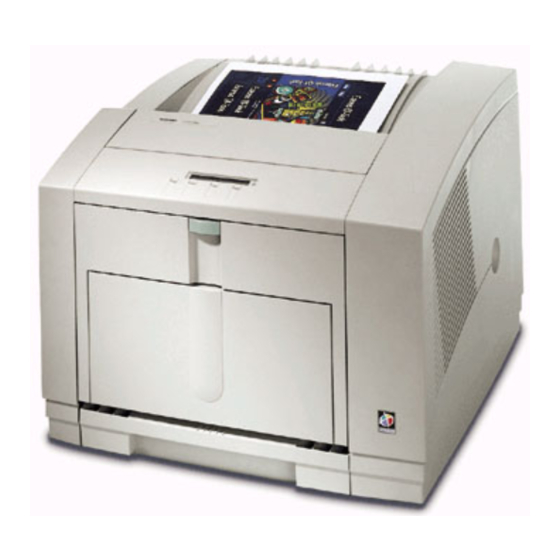
FRU list. To ensure complete understanding of the product, we recommend participation in Phaser 380 service training, if available. 9661-50 Figure 1-1 The Phaser 380 printer (shown with optional Lower Paper Tray Assembly) Service Manual... -
Page 20: Phaser 380 Overview
Phaser 380 and the Phaser 380 with Extended Features . The Phaser 380 prints at an addressability of 300 x 300 dots per inch (dpi) and features 39 built-in fonts and 16 Mbytes of RAM, which can be upgraded to 64 Mbytes. -
Page 21: Solid Inks
Solid inks, sometimes called phase-change inks, are solid at room temperature and are liquid at the higher temperature used during printing. The inks solidify almost instantly after being jetted onto the printer’s drum. Because Tektronix' proprietary solid inks bleed much less than ordinary liquid inks, they allow the printer to print brilliant colors on plain paper. -
Page 22: Print Engine Assemblies
Ink load assembly purge unit (raised position) Drum Transfix roller Process motor Paper Print preheater head Media width sensor assembly Maintenance tray X-axis drive Drum heater Y-axis motor 9661-51 Figure 1-2 Internal features of the print engine Phaser 380 Color Printer... -
Page 23: Figure 1-3 Circuit Boards Of The Print Engine (Right Front View)
General Information Ten circuit board support the printer’s electronics. Three board, called I/O board 1 through I/O board 3 supports the front panel, solenoids and sensors. The main board contains the printer’s two CPU processors, a 29K processor which executes the PostScript image processing and a 68K processor which controls the print engine. -
Page 24: Figure 1-4 Circuit Boards Of The Print Engine (Left-Front View)
General Information Network card Power control board Main board Power supply I/O board 1 9661-53 Figure 1-4 Circuit boards of the print engine (left-front view) Phaser 380 Color Printer... -
Page 25: Figure 1-5 The Printer's I 2 C Bus
General Information An internal data bus, called the I C bus, connects all I/O boards to the main board (through the power control board). Through this single bus, the main board can “poll” the I/O boards for the state of the printer’s sensors as well as actuate the printer’s solenoids. -
Page 26: Figure 1-6 Printhead Maintenance System Of The Print Engine
The system consists of a vacuum pump, a vacuum accumulator, a solenoid valve and a cap/wipe/purge assembly. Cap/wipe/purge Cap/wipe/purge unit assembly pump Vacuum accumulator valve 9661-55 Figure 1-6 Printhead maintenance system of the print engine Phaser 380 Color Printer... -
Page 27: Figure 1-7 Left-Side Sensors And Switches On The Print Engine
General Information Sensors in the printer provide information to the main board to determine the state of the printer. The printer monitors the positions of some of the movable assemblies, such as the drum, as well as the temperature of many other assemblies, such as the printhead, paper preheater and the drum. -
Page 28: Figure 1-8 Right-Side Sensors And Switches On The Print Engine
Exit cover open sensor Paper empty sensor Maintenance tray blade position sensor Right maintenance Cap/wipe/purge tray sensor assembly home sensor Media type sensors 9661-57 Figure 1-8 Right-side sensors and switches on the print engine 1-10 Phaser 380 Color Printer... -
Page 29: Figure 1-9 Solenoids And Clutches On The Print Engine
General Information Air valve Transfix cam solenoid Head tilt Upper feed roller solenoid electric clutch Maintenance tray electric clutch Lower feed roller electric clutch Paper pick solenoid clutch 9661-58 Figure 1-9 Solenoids and clutches on the print engine Service Manual 1-11... -
Page 30: Media Sensing
The media width sensor laterally scans the media to measure the width of the media once it is picked. Tabloid maximum B (Tabloid) Legal Executive Media Tray width sensors sensor Paper Transparency Front of printer 9661-127 Figure 1-10 Media tray sensors 1-12 Phaser 380 Color Printer... -
Page 31: The Main Board
General Information The main board The main board features two processors: one processor controls the functions of the print engine and the other provides PostScript image processing. Prominent on the main board is the ROM code SIMM and, underneath it, the optional font SIMM. -
Page 32: Rear Panel
The following figure illustrates the rear panel of the printer. 29K processor 68K processor health light health light PhaserShare™ Ethernet® Card Second Parallel SCSI Disk Feeder Service Only Service Reset 9661-60 Figure 1-12 Printer rear panel with the optional Ethernet card 1-14 Phaser 380 Color Printer... -
Page 33: Front Panel
General Information Front panel These front panel features are found on the printer: A two-line, 24-character LCD Four push buttons Two LEDs LCD. The LCD serves two purposes: displaying current image processor and print engine status information and displaying an interactive menu. Status information includes image processor status such as Ready , Receiving data and Printing . -
Page 34: Specifications
The printer should not be tilted more than 15 from horizontal for more than 1 minute while the printer is idle or the ink is hot (in liquid state) or if the maintenance tray is installed. 1-16 Phaser 380 Color Printer... - Page 35 Addressability Selectable 300 x 300 (Standard) or 600 x 300 (Enhanced) dots-per-inch (horizontal and vertical). Only Phaser 380 with Extended Features configuration can print at 600 x 300 dpi. Engine printing speed The time it takes from loading to ejecting on...
-
Page 36: Table 1-5 Electrical Specifications
+40 V -5%, +12% -40 V ± 10% +54 V ± 10% RF emissions Both 115 and 220 VAC-configured instruments pass these standards: FCC Part 15 Class B EN55022 (CISPR 22) Class B VCCI (CISPR 22) Class B 1-18 Phaser 380 Color Printer... - Page 37 General Information Table 1-6 Environmental specifications Characteristic Specification Temperature ° ° Operating to 32 C (59 to 90 ° ° Storage and shipping to 60 C (-22 to 140 Humidity Operating 10 to 80% relative humidity, non-condensing Non-operating 10 to 95% relative humidity, non-condensing Altitude °...
-
Page 38: Regulatory Specifications
General Information Regulatory specifications The Phaser 380 is in conformance with the following regulatory standards: FCC Part 15 Class B (for 115 VAC equipment) EN55022 (CISPR 22) Class B VCCI (CISPR 22) Class B The packaged product meets National Safe Transit Committee Test... -
Page 39: Installing The Printer And Drivers
Drivers This chapter discusses installing the printer and its drivers as a part of the S0 installation option. Tektronix Service Option S0 consists of three main functions detailed in this and the next two chapters of this manual: Chapter 2 “Installing the Printer and Drivers.” The first portion of installation instructions, this chapter, consists of five basic processes:... -
Page 40: Pre-Install Questions For Customers
Printer Name _____________________ Printer IP address__________________ Net Mask _________________________ Broadcast address _________________ Gateway__________________________ What software application packages will be used with the printer? (Some applications require special printing utility files.) _____________________________________________ Phaser 380 Color Printer... - Page 41 Customers must provide the particular interface cable or network adapter they need to use with the printer. Customers can purchase the following from the Tektronix Graphics Supplies Order Desk by calling 1-800-835-6100. Parallel cable, DB25-pin plug to Centronics 1284C 012-1468-00 Serial, 9-pin to 9-pin, 3 m (10 ft.), null modem...
- Page 42 2 Mbytes RAM, 2 Mbytes of hard disk space DOS systems DOS 3.1 or later An application that supports color PostScript or HP-GL Windows systems Windows 3.1 Windows 95 OS/2 Windows for Workgroups 3.11 Windows NT and Daytona Phaser 380 Color Printer...
- Page 43 Tektronix-confidential service support site cpidserv.wv.tek.com for the latest information regarding installing, servicing and supporting the printer. Additionally, you can access the Tektronix Highly Automated Library (HAL) during business hours, at 1-800-835-6100 (ask to be transferred to HAL) for articles that may help with installing the printer into a customer's network. You can call HAL directly at (503) 682-7450, 24 hours a day, 7 days a week.
-
Page 44: Unpacking
Ink sticks Maintenance tray Paper sampler User manual Installation instructions Phaser printing utilities and driver diskettes or CD Optional Lower Paper Tray Assembly (with paper tray) PhaserShare network utilities user manual (optional) PhaserShare utilities diskette (optional) Phaser 380 Color Printer... -
Page 45: Figure 2-1 The Printer Packaging
Installing the Printer and Drivers 220 lbs. 100 kg 9661-62 Figure 2-1 The printer packaging Service Manual... -
Page 46: Setting Up The Printer
Installing the Printer and Drivers Setting up the printer Installing the printer is explained in detail in the Phaser 380 Color Printer User Manual . The following is a brief list of the steps you follow to unpack and set up the printer. - Page 47 Installing the Printer and Drivers Install the printer’s maintenance tray and paper tray. Note that when a new maintenance tray is installed, the printer requires a 15-to-20 minute wait before it will print. Installing RAM SIMMs . The standard configuration of the printer includes 16 Mbytes of RAM.
-
Page 48: Cabling The Printer
If the network has multiple zones, the network router assigns the printer a default zone name. The printer’s configuration page lists the zone name. The topic, “Printing the configuration page” on page 9-5, explains printing this page. 2-10 Phaser 380 Color Printer... -
Page 49: Connecting The Printer To A Pc
Installing the Printer and Drivers Connecting the printer to a PC Direct connection to a PC Turn off the printer. Turn off the host computer. Attach the parallel interface cable to the host computer; attach the other end to the printer. Turn on the printer first and then the computer. -
Page 50: Installing A Scsi Hard Disk Drive On A Phaser 380
Reset SCSI 9661-64 Figure 2-3 Connecting a SCSI hard disk drive to a Phaser 380 Turn on the disk drive first, and then the printer. Refer to the Phaser 380 Driver and Utilities Printing Reference for details on formatting a SCSI disk, controlling Sys/Start job files, and using the LaserWriter Utility to load fonts onto the disk drive. -
Page 51: Connecting The Optional Copystation To The Printer
Service Reset SCSI 9661-65 Figure 2-4 Connecting a CopyStation to a Phaser 380 Note The CopyStation uses two SCSI address; they are preset to 5 and 6. Make sure that any connected SCSI hard drive does not use these addresses. -
Page 52: Turning On The Printer
Turning on the printer Startup page When you turn on a Phaser 380 printer, it executes a series of self-tests to determine if there are any problems with the PostScript interface. After running self-tests and reaching the “Ready” state, the printer prints a startup page (if the startup page has been enabled). - Page 53 Tektronix version number of the not applicable version number PostScript firmware running on the printer’s 29K processor. Print engine Tektronix version number of the engine not applicable FW version firmware running on the printer’s 68K number processor. Read from ROM and stored in NVRAM.
- Page 54 SCSI Disk Indicates if a SCSI disk is attached to Not connected On-line, total space, free space. the printer. Also indicates its storage Uninitialized. capacity and the amount of free space. 2-16 Phaser 380 Color Printer...
- Page 55 Installing the Printer and Drivers Table 2-1 Configuration page settings (cont'd.) Parameter Description Saved Default Limits or alternate choices NVRAM Execute Determine whether or not to run the Skip Sys/Start Job system start file during system initiation. Boot Delay Number of seconds the printer waits Any positive integer.
- Page 56 Integer assigned by network the printer on the network. NetWare port Indicates the type of interpreters in use Auto Select Disabled, <interpreter> interpreter at the port (Phaser 380 only). Print server Name of the printer server. TEK01B009, user-defined name hardware-...
- Page 57 Indicates the type of interpreter in use Not Authorized, Disabled, <null interpreter at the BSD system configured port string> (Phaser 380 only). LPR Host List of TCP/IP network addresses for Unrestricted, only first 16 access list host access to printer.
- Page 58 String of 0 to 255 characters System contact Name and phone number or address String of 0 to 255 characters of person responsible for the printer. System location Location of the printer. String of 0 to 255 characters 2-20 Phaser 380 Color Printer...
- Page 59 Installing the Printer and Drivers Table 2-1 Configuration page settings (cont'd.) Parameter Description Saved Default Limits or alternate choices NVRAM Trap Hosts A list of hosts, one for each protocol, None None, which are able to receive traps. N.N.N.N/Public, N.N.N.N/Proxy, N.N.N.N/Private, N.N.N.N/Regional, N.N.N.N/Core...
-
Page 60: Driver And Communication Set Up
Insert either the printer’s CD-ROM or the first Macintosh diskette into the appropriate drive on your computer. Double-click the Phaser 380 Installer icon. Click Continue until the Easy Install window appears. Select Easy Install or Custom Install: For Easy Install a. -
Page 61: Setting Up The Phaser 380 Printer Driver
Select Chooser from the Apple menu after installing the printer’s software. Click on the icon of the Phaser 380 printer driver (on the left side of the Chooser). Click on the Zone for your printer. See your network administrator if you have questions. -
Page 62: Setting Up The Phaser 380 Gx Printer Driver
Select Chooser from the Apple menu after installing the printer’s software. Click on the icon of the Phaser 380 GX printer driver (on the left side of the Chooser). Click on the Zone for your printer. See your network administrator if you have questions. -
Page 63: Installing A Printer Driver For Microsoft Windows 95
For best performance and added features when printing from Windows 95, use the Windows 95 printer driver (as opposed to the Windows 3.1 printer driver, which may cause printing problems in Windows 95). The Phaser 380 Color Printer User Manual gives the step by step procedure you follow to perform this configuration. - Page 64 Extended Features: Yes or No. 14. Select the port the printer is connected to, and click Next. 15. Enter a name for the printer, and select the Phaser 380 as the default printer if desired, and click Next.
-
Page 65: Installing Printer Software For Windows
Installing the Printer and Drivers Installing printer software for Windows NT 4.0 Insert either the printer’s CD-ROM or the Windows Disk 1 into the appropriate drive on the computer. Click the Start icon in the taskbar, and select Run. Type in the drive for the CD-ROM or diskette, type SETUP.EXE, and click OK. - Page 66 If you are not sure of the printers’s version, check the printer’s startup page for Extended Features: Yes or No. 13. Enter a name for the printer, and select the Phaser 380 as the default printer if desired, and click Next.
-
Page 67: Installing Printer Software For Windows Nt 3.51
Installing the Printer and Drivers Installing printer software for Windows NT 3.51 Insert either the printer’s CD-ROM or the Windows Disk 1 into the appropriate drive on the computer. Select Run from the File menu. Type in the drive for the CD-ROM or diskette, type SETUP.EXE, and click OK. - Page 68 10. In the Select Driver dialog box, under Printer Driver, select the Phaser 380 printer, and click OK: Tektronix Phaser 380 Extended (Extended Features option) Tektronix Phaser 380 (standard printer configuration) If you are not sure of the printers’s version, check the printer’s startup page for Extended Features: Yes or No.
-
Page 69: Installing Printer Software For Windows 3.1
Note: The Tektronix Printer Driver for Windows 3.1 must be installed in the Windows directory (default Destination Directory). Do not change the Destination Directory when installing the Tektronix driver unless you are installing the driver on a network and you know the location of the Windows directory on the network drive. - Page 70 Go on to the setup instructions. Tektronix Driver for Windows 3.1: Setup instructions If you selected Easy Installation, or if you selected the Tektronix Driver for Windows 3.1 in the Custom Installation, continue with the following instructions: 1. Open the Windows Control Panel.
-
Page 71: Setting Up The Printer On A Network (Windows Nt 3.5 And 3.51)
Installing the Printer and Drivers Setting up the printer on a network (Windows NT 3.5 and 3.51) TCP/IP connection Note Windows NT 3.5 and 3.51 include network software called Services for Macintosh (AppleTalk) and TCP/IP print services (for TCP/IP; lpr print services). Refer to the Windows NT manual for instructions on installing this network software. -
Page 72: Appletalk Connection
Select AppleTalk Printing Devices for Available Print Monitors; click OK. Double-click on the appropriate zone (if there are multiple AppleTalk zones). Select the Tektronix printer and click OK. At the prompt Do you want to capture this AppleTalk Printing Device?, click No. Note... -
Page 73: Setting Up The Printer On A Network (Windows Nt 4.0)
Installing the Printer and Drivers Setting up the printer on a network (Windows NT 4.0) To add or update the driver on a Windows NT 4.0 Server or Workstation Note You must have the original Windows NT 4.0 diskettes (or CD-ROM) to complete this procedure. - Page 74 14. Type in the path name to the requested files, then click OK. (The files are usually in the I386 directory for Intel-based Windows NT servers.) 15. If you printed a Test Page, check if it printed; then click OK. 2-36 Phaser 380 Color Printer...
-
Page 75: Workstation Software - Downloadable Printer Utility Files
Look in the .bin directory for workstation-specific files. Mount the printer’s PC diskette 1 and copy the files to your workstation’s hard drive. Access the Tektronix anonymous ftp site on the Internet at ftp.tek.com. Download utility files from the Tektronix Bulletin Board Service (BBS). -
Page 76: Setting The Printer's Ip Address Using The Front Panel
PCL or UNIX-host TCP/IP printing. As an alternative you can download the editable PostScript snippet IPconfig.ps to the printer. the snippet is available on the Tektronix web page, bulletin board and the printer’s CD-ROM. -
Page 77: Configuring The Printer's Serial Port For A Pc
Installing the Printer and Drivers Configuring the printer's serial port for a PC Use the PostScript command file DEVPARAM.PS (located on the Printers Utilities diskette) to modify the printer’s serial port settings. The following example sets flow control to Xon/Xoff, parity to none, data bits to 8, stop bits to 2 and the baud rate to 9600. - Page 78 TBCP Use the DOS COPY command to send DEVPARAM.PS to the printer; for example: COPY DEVPARAM.PS COM1: (Substitute the appropriate port for COM1:.) Similarly, use the DOS COPY command to send CTRLD.PS to the printer 2-40 Phaser 380 Color Printer...
-
Page 79: Configuring A Novell Netware 3.X Server For The Printer
The PhaserShare Network Cards and Software System Administrator User Manual gives the step by step procedure you follow to perform this configuration. Also refer to the Tektronix web pages www/tek./com/Color_Printers/userdocs for the latest install information. There are two methods, each using a different utility program, you can use to configure the file server and set up print queues. -
Page 80: Configuring Novell Netware 4.X Server For The Printer
You can have a total of 32 queues on up to eight file servers. After all file servers have been configured, save the configuration file and restart the print server. Then restart the printer. 2-42 Phaser 380 Color Printer... -
Page 81: Configuring Tcp/Ip On A Unix Host
Add the printer name to the host table (/etc/host) and assign an IP address to the printer’s name. Assign a print queue to the printer. If necessary, refer to the Tektronix web page http://www.tek.com/Color_Printers/userdoc/PShare3/ tcpunix.html”, for the latest information on host-specific, TCP/IP configurations. - Page 82 The bye command terminates the connection. ftp 134.67.66.11 put sample-file.ps Telnet. If the printer is to be used with standard TELNET clients, the DataPortNumber parameter must be set to 23 decimal (23 is the default). 2-44 Phaser 380 Color Printer...
-
Page 83: Verifying The Printer And Host Connections
Chapter Verifying the Printer and Host Connections In this chapter, you verify that the host computer can send files to the printer. This chapter assumes that the printer and the printer drivers have been properly installed as explained in the previous chapter, “Installing the Printer and Drivers.”... -
Page 84: Windows 3.1 Driver Verification
Type in a line of text such as THIS IS A TEST . Click the File menu item and select Printer Setup... from the menu list. Select Phaser 380 , (whichever applies) from the displayed list of available printer drivers. Click OK . -
Page 85: Novell Netware Verification
(Point to any printer object, click the right mouse button, click on Select Default , and click on Phaser 380.) This is a simple way to be sure that all printers are set up correctly. -
Page 86: Windows Nt
This loads the error handling utility into the printer's memory where it remains until the printer is turned off. Send a file to the printer as explained in the previous procedure. If an error occurs, the printer will print a page listing the error. Phaser 380 Color Printer... -
Page 87: Verifying Printing From A Macintosh
Displayed on the right side of the dialog box are a list of printers that the selected driver will print to. Select the newly installed printer Phaser 380. (If, for example, a Phaser 380 printer is already on the network with the name Phaser 380, then the newly installed printer will be named Phaser 380-1.) -
Page 88: Printing The Directory From A Macintosh
(such as both LocalTalk and Ethernet). Refer to, “Troubleshooting” on page 6-1 for more information about networks. More troubleshooting tips are included in the reference manual Phaser 380 Drivers and Utilities Printing Reference. Printing the directory from a Macintosh Make sure that you have an open window displayed on the screen (such as the hard disk drive's window). -
Page 89: Using The Error Handler Utility
If problems occur at this point, download the error handling utility to the printer as explained in the next procedure. Contact the Customer Support Hotline at 1-800-835-6100. Refer to the Phaser 380 User Manual. Each provides information on using the printer with specific applications. -
Page 90: Verifying Printing From A Workstation
Verifying printing from a workstation Verifying and printing using the TCP/IP protocols The Phaser 380 accepts files from networked UNIX and VMS workstations using TCP/IP communications. The printer supports BSD UNIX 4.3, AT&T's UNIX System V with BSD 4.3 lpr extensions, and DEC VMS with Tektronix PhaserSym software. -
Page 91: Using The Error Handler Utility
Verifying the Printer and Host Connections To print to the Phaser 380 printer in the VMS environment, you must have the symbiont PhaserSym running on the host. To print to the printer from the host, you must first have the printer’s queue established. This is site-dependent and requires the aid of the site’s network administrator. -
Page 93: Key Operator Training
Chapter Key Operator Training This chapter covers the last portion of the Tektronix Service Option S0 installation: Training the printer's key operator. The steps you follow here place an emphasis on encouraging the key operator to read and use the printer's user manual to operate, clean, and care for the printer. -
Page 94: Printer Controls And Indicators
Network connections: Explain the different types of Phaser Share cards that provide printer connectivity. Show where these connections are explained in the user manual and where to find more information about expanding their printing system with other network options, cables, and accessories. Phaser 380 Color Printer... -
Page 95: Loading Consumables
Ink sticks: Demonstrate how to load a ink sticks. Emphasize to customers to use only Phaser 380 Color Printer ink sticks. Also emphasize that they should not use ink sticks that have large pieces missing and not to load any small broken pieces. -
Page 96: Cleaning
film must be loaded in the printer. Using TekColor color corrections: Explain that different color correction modes are available and where to find more information in the user manual. Phaser 380 Color Printer... -
Page 97: Moving The Printer
United States: Customers can call toll-free at 1-800-835-6100 (ask for the Color Printing Supplies Order Desk) to place a supplies order. Open Monday through Friday, 6:00 am to 5:00 pm (PST). Shipments are made within 24 hours. Outside the United States: Contact your nearest Tektronix dealer. Service Manual... -
Page 98: If You Need Help
Key Operator Training If you need help If a customer needs assistance, have then contact a local Tektronix dealer or sales representative or any of these listed resources: Type of service How to access Details Online services Technical support, Technical support: support@ColorPrinters.tek.com... -
Page 99: Receiving Email Update Notices
Receiving email update notices Using the World Wide Web, you can register to receive email notification of new printer drivers, accessories and upgrades for your Tektronix Phaser color printer as they become available. To subscribe to this free service, simply follow these... -
Page 100: Using The Automated Fax Systems
Using the automated fax systems As an alternative to other resources, and to provide up-to-date information quickly, Tektronix has set up HAL (Highly Automated Library) and EuroHAL, two interactive, automated fax systems. These automated fax systems provide Macintosh, PC, and workstation users with the latest technical hints and tips... -
Page 101: Customer Support Hotline
Key Operator Training If customers’ telephones do not have these keys or have a dial, they will need to buy a tone dialer from their local telephone or electronics shop. This small box is held to the phone and will send the standard tones that are needed to talk to EuroHAL. -
Page 102: Service Support
Key Operator Training Service support If the printer needs service, customers should contact their Tektronix service representative at 1-800-835-6100 in the United States. Customers should be prepared with the printer type, serial number and, if applicable, print samples revealing the problem. -
Page 103: Theory Of Operation
Chapter Theory of Operation Overview This chapter covers the theory of operation of each subsystem within the printer: Functional block diagram Printer electronics Printhead X-axis system Cap/wipe/purge assembly Drum/transfix assembly Drum maintenance tray Ink loader Paper preheater Media width unit Paper tray Exit unit Print process in operation... -
Page 104: Functional Block Diagram
Power supply Exit unit loader Drum Transfix roller Power control Paper board preheater Net card Media width unit Main board Maintenance tray Power supply X-axis drive Universal tray system 9661-67 Figure 5-1 Overview of the printer Phaser 380 Color Printer... -
Page 105: Printer Electronics
Theory of Operation Printer electronics Main board Power control board I/O boards (3) Network card Power supply Main board The main board performs two functions: it controls the actions of the print engine and it performs the PostScript interpreting of the host’s data file into a bitmap format to be printed by the print engine. -
Page 106: Power Control Board
I/O boards. The power control board drives the following components: Process motor Drum (Y-axis) motor X-axis motor Cap/wipe/purge motor Media width motor Vacuum pump Rear fan Drum fan Phaser 380 Color Printer... -
Page 107: I/O Boards
Theory of Operation I/O boards The three I/O boards contain the most of the printers sensors and solenoids. An internal data bus, called the I C bus, connects all I/O boards to the main board. Through this single bus, the main board can “poll” the I/O boards for the state of the printer’s sensors as well as actuate the printer’s solenoids. -
Page 108: Power Supply
Even with the power switch in the OFF position, AC line voltages are present on the power supply, heaters and heater wiring. The power cord must be removed for disassembly. There are no field adjustments necessary on the power supply. Phaser 380 Color Printer... -
Page 109: Figure 5-2 Power Supply Block Diagram
Theory of Operation +40V +54V -40V +12V -12V Drum heater 1 F° Reservoir heater 1 F° Black ink melter Magenta ink melter Cyan ink melter Power Yellow ink melter Cap/wipe/purge unit heater F° Jet stack left Paper pre-heater F° Jet stack right Reservoir heater 2 F°... -
Page 110: Printhead
The level is detected by a sensor probe which senses the conductance of the ink at the probe tip. The illustration below shows a cross-section of the ink-jet array and the jet nozzle arrangement. Phaser 380 Color Printer... -
Page 111: Figure 5-4 The Ink-Jet Array Nozzle Arrangement And Cross-Section
Theory of Operation Ink inlet Manifolds Piezoelectric crystals Color nozzles 28 pixels Black nozzles 24 pixels 24 pixels 12 pixels 2 pixels 9661-130 Figure 5-4 The ink-jet array nozzle arrangement and cross-section The printhead can be tilted backwards to provide for printhead maintenance, printhead protection during transport, and for thermal isolation. -
Page 112: Figure 5-5 The Printhead Tilting Mechanism
Printhead print position Drum Printhead Tilt cam gear X-axis pivot point follower pin Cam groove Printhead maintenance position Print positon Cap/purge Maximum tilt back Wipe Cam gear positions 9661-74 Figure 5-5 The printhead tilting mechanism 5-10 Phaser 380 Color Printer... -
Page 113: X-Axis Drive System
Theory of Operation X-axis drive system The X-axis drive system controls the lateral, left-to-right, motion of the printhead for imaging. X-axis movement of the printhead is accomplished by a motor-driven pulley system. A stepper motor, driving through a two-stage reduction gear, turns a capstan. The capstan, in turn, drives a stiff, yet flexible, split-metal band which attaches to each end of a frame supporting the printhead. -
Page 114: Cap/Wipe/Purge Assembly
When servicing the printer be careful of the cap/wipe/purge assembly as it passes the printhead. If a damaged wiper blade of cap/wipe/purge assembly catches on the printhead it could flip hot liquid ink upward into your face. 5-12 Phaser 380 Color Printer... -
Page 115: Figure 5-8 The Cap/Wipe/Purge Assembly And Vacuum System
Theory of Operation Vacuum for the purge cycle is obtained from a vacuum pump and a vacuum accumulator. A small vacuum pump, running for about 75 to 90 seconds, creates a strong vacuum in the vacuum accumulator. Then an air valve is energized for a fraction of a second, exposing the printhead faceplate to the strong, accumulated vacuum to suck debris and bubbles out of the printhead nozzles. -
Page 116: Drum/Transfix Assembly
A temperature sensor in contact with the drum surface monitors the drum’s temperature. The main board interprets the sensor’s signal and turns on the drum heater and fan to heat the drum, or turns on the drum fan alone to cool the drum. 5-14 Phaser 380 Color Printer... - Page 117 Theory of Operation The drum is driven by a closed-loop servo motor which, through a double reduction belt drive, rotates the drum at 112.8 rpm for imaging and a constant low speed for image transfer to paper. Temperature Home sensor sensor (~49°C) Encoder disk...
-
Page 118: Drum Maintenance Tray
When it interrupts its sensor, it indicates the maintenance cartridge must be replaced. The sensors are mounted on the inside of the printer frame. 5-16 Phaser 380 Color Printer... -
Page 119: Ink Loader
Theory of Operation Ink loader The ink loader consists of four parallel channels with an ink melting element at the end of each of the four channels. Ink sticks, one color loaded in each channel, are pressed by constant force springs into the melting elements. The printer uses pixel counting, melt rates, purge accounting and ink-level signals from the printhead to determine ink levels in the printhead and when to activate the ink melters. -
Page 120: Paper Preheater
“first” print job. Exit unit The exit unit’s gear train transports the printed copy to the exit tray. The gear train is driven by a ring gear on the end of the drum. 5-18 Phaser 380 Color Printer... -
Page 121: The Paper Path
Theory of Operation The paper path Figure 5-12 illustrates the path of a sheet of media as it travels from the paper tray to the exit tray. Exit rollers Transfix roller on eccentric shaft Paper preheater Exit sensor exit sensor Paper preheater Upper feed... -
Page 122: Print Process In Operation
To tilt the printhead back, the head tilt solenoid is energized to allow the head tilt cam gear (with a slight spring assist) to advance enough to engage its drive gear. 5-20 Phaser 380 Color Printer... -
Page 123: Figure 5-13 Tilting The Printhead
Theory of Operation Process motor Head tilt arm Head tilt Process cam gear drive belt One way clutch Head tilt compound gear solenoid Head tilt cam Head tilt cam gear disengaged gear latched by from drive gear head tilt solenoid 9661-83 Figure 5-13 Tilting the printhead Service Manual... -
Page 124: Paper Pick And Measurement
Measuring is always preformed on a manually-fed print job before image deposition on the drum to confirm the media matches the size the printer was expected to be fed. 5-22 Phaser 380 Color Printer... - Page 125 Theory of Operation Upper feed rollers Paper pick Media width handfeed sensor sensor Lower feed rollers Upper feed roller Upper feed roller electric clutch Lower feed roller Pick Pick roller roller clutch Lower feed Paper pick roller electric solenoid clutch 9661-87 Figure 5-14 Paper picking and positioning for transfixing Service Manual...
-
Page 126: Drum Preparation
The stripping operation is timed so the fingertips avoid the oil bar which would stain the edge of the print as the print is stripped off of the drum. 5-24 Phaser 380 Color Printer... -
Page 127: Figure 5-15 Drum Preparation For Printing
Theory of Operation Process motor Camshaft home position flag Drum maintenance tray camshaft Process drive belt Compound gear Maintenance tray electric clutch Drum Cam pushes wick and blade against drum Drum Cam lowers wick but leaves blade against drum 9661-84 Figure 5-15 Drum preparation for printing Service Manual 5-25... -
Page 128: Printing
112 pixel-wide field that each jet travels, the pixel columns of any one jet actually interlaces with the pixel columns of six other jets, although no more than four at any one time. 5-26 Phaser 380 Color Printer... - Page 129 Theory of Operation In reality, because of the fixed width of the printhead and inter-jet spacing, the outermost jets cannot interlace completely with their adjacent jets for full-width, A-size page images with only 5mm(0.25”) side ISO margins. In this case, the drum rotates for seven extra imaging rotations (14 if both end jets are needed) for the printhead to reposition the end jets so they can fill-in the missing pixel columns that cannot otherwise be interlaced.
-
Page 130: Figure 5-16 Printing The Single Scan Pre-Transfer Image On The Drum
1 of 4 beginning columns of the next set of 2 of 4 four jets. 3 of 4 4 of 4 9661-85 Figure 5-16 Printing the single scan pre-transfer image on the drum 5-28 Phaser 380 Color Printer... -
Page 131: Figure 5-17 Printing The Double Scan Pre-Transfer Image On The Drum
Theory of Operation Double scan image deposition. B-size or wide-format images are placed on the drum using two scans the printhead separated by a long non-deposition skip move. The image is laid down on the drum in the same manner as a single scan image using 4-jet interlacing, except the image is divided into two halves. -
Page 132: Transfixing, Stripping And Exiting
At this point, the transfix roller shaft rotates slightly so a lobe on the transfix roller cam pushes the exit roller gear train into contact with the ring gear on the right end of the drum. As the drum rotates, the exit rollers now rotate. 5-30 Phaser 380 Color Printer... - Page 133 Theory of Operation The process motor stops, leaving the transfix roller cam in its half-rotated position. Friction from the rotating drum continues to turn the transfix roller, which freely rotates on the transfix roller shaft. The ink on the drum transfers to the sheet of paper pulled by the friction between the drum and the transfix roller.
- Page 134 If the paper is too short, transfixing will be interrupted and a chase sheet will follow to remove the remainder of the image. 5-32 Phaser 380 Color Printer...
-
Page 135: Printer Self-Maintenance
Theory of Operation Printer self-maintenance To maintain peak operation reliability and print quality, the printer has several automatic or semi-automatic maintenance functions. These functions may be started automatically after a certain number of prints or during printer startup, or they may be started by the customer if a print quality defect is noted. Printhead maintenance cycle Paper preheater cleaning Transfix roller oiling... - Page 136 first wipe. Short flush. The printhead is tilted back slightly and the cap/wipe/purge assembly is raise to bring the wiper blade even with the jet nozzles. All jets are fired again for 0.6 seconds. 5-34 Phaser 380 Color Printer...
-
Page 137: Figure 5-19 The Printhead Maintenance Cycle
Theory of Operation Following the short flush, the printhead is tilted back and the cap/wipe/purge assembly is lowered into its standby position. A cap/wipe/purge sensor on I/O board 2 detects when the cap/wipe/purge assembly is stored in its standby position. Then the printhead is tilted forward into its print position and a “flush”... -
Page 138: Paper Preheater Cleaning
(The user must remove all media from the paper tray and also soak the cleaning tray’s scrubber with alcohol.) The customer starts the cleaning cycle; the printer responds by rotating the pick rollers eight times. 5-36 Phaser 380 Color Printer... -
Page 139: Transfix Roller Oiling
Theory of Operation The printer prompts the customer to remove the cleaning tray and returns to the cleaning menu. The procedure is the same for the lower paper tray assembly except you select the lower tray for cleaning. Transfix roller oiling Transfix roller oiling conditions the roller and prevents ink from transferring to the roller during duplex printing. -
Page 140: Power-Down Cycle
Tilt the printhead to the standby position. c. Move the x-axis left to engage the left head restraint pin. d. Tilt the printhead slightly to its restraint offset position. Initiate software-controlled power supply shut down. 5-38 Phaser 380 Color Printer... -
Page 141: Troubleshooting
Chapter Troubleshooting This chapter discusses troubleshooting the printer. Troubleshooting is discussed with two approaches: A step-by-step verification procedure that systematically confirms that particular components of a printer are properly functioning until a problem is found. A symptom/cause scheme that lists particular printer failures and error codes and their possible causes. - Page 142 The printhead is moved to its X-axis home position and then centered. e. A short wipe is performed and the cap/wipe/purge assembly is returned to its home position. Phaser 380 Color Printer...
- Page 143 Troubleshooting The printer energizes the process axis and y-axis motors eight times at different current levels to determine at which point they stall, these values are stored in NVRAM and are used to determine when abnormal events occur, such as double-picks or jams that stall the motors.
-
Page 144: Print Engine Troubleshooting
4 can be caused by a defective or incorrect RAM SIMM in SIMM 1 connector or possibly the image processor board. (SIMM1 can only be a 16-Mbyte RAM SIMM.) Error 7 can occur due to a defective RAM SIMM in SIMM 2 or SIMM 3. Phaser 380 Color Printer... -
Page 145: Table 6-2 68K Processor Power Up Self-Test Error Codes
Troubleshooting Observe the right LED; it represents tests on the main board’s print engine 68K processor. During power-up the LED flashes twice and then stays lighted. It then blinks intermittently as the processor test runs. Like the 29K LED, if it blinks in a, repeated pattern, the processor is looping on a failed test. -
Page 146: Verifying Print Engine Operation By Using Its Test Print
With the VOM set to measure AC voltages, measure the power being supplied to the printer. It should measure between 87 to 128 VAC (115 VAC nominal) or 174 to 250 VAC (220 VAC nominal). Ensure that the rear panel voltage switch is correctly set. Phaser 380 Color Printer... -
Page 147: Inspecting The Power Supply Fuses
Troubleshooting Inspecting the power supply fuses Three fuses (F1, F2 and F3) are mounted on the power supply. F1 is the input fuse for the DC power section of the supply. F2 and F3, heater fuses, are located under a daughter card mounted on the supply. Turn off the printer and remove the power cord. -
Page 148: Ac Triac Drive Signal
If a heater shorts, the power supply does NOT shut down; however, a Service Required error code is displayed on the front panel. Using the Tektronix DMM 252/254 set for Hz (also, press the blue button), measure the heater triac control lines test points located along the top edge of the power control board. -
Page 149: Testing For A Shorted Dc Load
Troubleshooting Testing for a shorted DC load The power supply may shut down because of a shorted load. Turn the printer off. Disconnect the DC power cables: J13, J14, J15, J16, J18, J19, J20, J22 and J24, from the power control board. Turn the printer on (this isolates all motors). -
Page 150: Testing Motor And Solenoid Resistances
Upper feed roller electric clutch 150 ohms Lower feed roller electric clutch 150 ohms In general, if you measure any low resistance from a motor winding to ground while the motor is installed, replace that motor. 6-10 Phaser 380 Color Printer... -
Page 151: Media Jams And The Paper Path
Troubleshooting Media jams and the paper path Required tools TORX screwdriver and tips Jams fall into the following four categories: Media-based problems Paper-picking errors Paper-feeding errors Paper-ejecting errors Media-based problems Check that the correct type of media is being used. Fanning the media eliminates its tendency to double-pick. -
Page 152: Print Transfer Jams
Disconnect the motor's wiring harness. Measure the resistance of the motor's windings. The expected resistances are listed in Table 6-4 “Motor and solenoid resistances,” on page 6-10. If the windings are opened, shorted or far out of tolerance, replace the motor. 6-12 Phaser 380 Color Printer... -
Page 153: Media Skews Passing Through The Paper Path
Troubleshooting If the motor’s winding resistances are within specification, inspect the wiring harness for nicks, crimps, opens or other problems. If the harness is functional, then replace the power control board. Inspect the gear train on the inside of the printer frame; look for stripped gears or broken teeth. -
Page 154: Streaks Or Lines In The Print Parallel To The Long Axis Of Printing
Replace the maintenance tray. Replace the power control board. Non-functioning printhead data cable. Replace the main board. Replace the printhead. 6-14 Phaser 380 Color Printer... -
Page 155: Color Is Uneven
Troubleshooting Color is uneven This may be due to poor thermal regulation in the printer, resulting in uneven heating of the printhead, which in turn results in uneven ink drop jetting. Likewise uneven heating of the drum, left to right, can cause uneven colors. -
Page 156: Table 6-5 Front Panel And Fault History Log Error Codes And Messages
This printhead's NVRAM contains a format of data not supported by this PC_DEV_FAULT_HEAD_NV_ version of firmware. The printhead or firmware must be replaced. FORMAT 4,012.42 (0x240C) Ambient temperature is less than ten degrees Centigrade. The printer PC_DEV_FAULT_AMBIENT_TO cannot be warmed up under these circumstances. OCOLD 6-16 Phaser 380 Color Printer... - Page 157 Troubleshooting Table 6-5 Front panel and fault history log error codes and messages (cont'd.) Error code Meaning 4,013.43 (0x240D) Printhead temperature has dropped below the head-clean-needed PC_DEV_FAULT_LATE_CLEAN_ threshold. This condition occurred after the warm-up sequencer had REQUEST determined a head clean operation was not needed. 4,014.44 (0x240e) Timeout during turn feed rollers.
- Page 158 WIDTH_SENSE media through the paper preheater: Clean feed rollers. Check for media or ink contamination in the preheater mechanism. Check for a sticky or inoperative preheat exit sensor. 6-18 Phaser 380 Color Printer...
- Page 159 Troubleshooting Table 6-5 Front panel and fault history log error codes and messages (cont'd.) Error code Meaning 7,002.44 (0x3c02) No transitions are observed of the compound gear sensor when the PM_FAULT_COMPOUND_GEAR compound gear should be turning. Perhaps the sensor is bad (it falls off _SENSOR_BAD easily), or the process motor to compound gear linkage is broken.
- Page 160 Do not open the door during these operations. Ensure that the access doors are closed. Check for a sticking or defective access door sensor 6-20 Phaser 380 Color Printer...
- Page 161 Troubleshooting Table 6-5 Front panel and fault history log error codes and messages (cont'd.) Error code Meaning 11,058.30 (0x5b3a) Jam -- lower tray removed. The specified tray was removed during a print or DMC_STATUS_AUX_TRAY_ drum clean operation when media was in the paper path: Do not remove TYPE_REMOVED the trays during these operations.
- Page 162 24,009.17 Engine is stuck while purging the printhead. 24,010.18 Engine is stuck while wiping the printhead. 24,011.10 Engine is stuck while oiling the rollers. 24,012.11 unused 24,013.12 Engine has a fault but won't indicate why. 6-22 Phaser 380 Color Printer...
- Page 163 Troubleshooting Table 6-5 Front panel and fault history log error codes and messages (cont'd.) Error code Meaning 24,014.13 Engine is stuck while powering down. 24,015.14 unused 24,016.15 Engine is stuck while oiling the drum. 24,017.16 Engine is stuck while turning the pick rollers. 24,018.17 Engine is stuck while warming up -- thermals won't stabilize.
-
Page 164: Pc-Based Diagnostics
C:\380DIAGS\<version number>\ is the default. To install the diagnostics from the diskette onto your computer: type: A:INSTALL<return>. A message prints on your screen detailing the options and method for installing the diagnostic set. 6-24 Phaser 380 Color Printer... -
Page 165: Starting The Diagnostics
Turn on both the printer and your computer. The printer indicates it is in Service Mode by displaying the engine ROM version on the front panel: “Tektronix V x.xx.” In the case of a Apple PowerBook, select AppleTalk Inactive from the file PowerBook control strip menu. - Page 166 (where xxx is the engine ROM version). Once launched, the program repeatedly attempts to communicate with the printer. The link status indicator, in the bottom-right corner of the screen, reads “NO” until this link is established; once communication is established, it reads “OK.” 6-26 Phaser 380 Color Printer...
-
Page 167: Figure 6-3 Pc-Based Diagnostics Screen Display
Troubleshooting Once communication with the printer is made, the diagnostics display the following screen on the computer: Figure 6-3 PC-based diagnostics screen display The start-up screen features the following elements: A conventional-looking Menu Bar across the top of the screen; all diagnostic functions are accessible via this menu. -
Page 168: Selecting Tests
Alt-R (Control R — Mac) – select the currently highlighted test opens the Run window to prepare to execute the currently selected tests. 6-28 Phaser 380 Color Printer... -
Page 169: Figure 6-4 The Diagnostics Global Help Screen
Troubleshooting Alt-H (Control H — Mac) – Opens a small Help window which serves to remind the functions that are available. Press Escape or Enter to make it go away. Figure 6-4 The diagnostics global help screen F1 – Brings up a more complete description about the currently highlighted test. -
Page 170: Running Tests
Note The test System Verification is a good, general purpose test of all the printer’s sub-systems. It is a particularly good test to run when you are unsure of the cause of a printer’s problem. 6-30 Phaser 380 Color Printer... -
Page 171: Figure 6-6 The Individual Test Within A Selected Test Suite
Troubleshooting Once you select a test suite, the individual tests of that suite are displayed. Figure 6-6 The Individual test within a selected test suite Press the space bar to select or deselect a test. You can select as many tests as you like. -
Page 172: Figure 6-8 An Individual Test Help Screen
Figure 6-8 An Individual Test help screen The Sensor Test shows you the real-time state of the printer’s sensors. You can manually interrupt the sensors to determine if they operate correctly. Figure 6-9 Sensor Test summary 6-32 Phaser 380 Color Printer... -
Page 173: Figure 6-10 The Thermal Test
Troubleshooting The Thermal Tests let you select, start and observe the operation of the printers heaters and determine if they are operational. The test displays the real-time temperature of active heaters. A simple graphic of a vertical bar”|” between two brackets [..|..] show that the temperature is within its expected range. If the symbol “|”... -
Page 174: Saving And Restoring Test Selections
Any user-configurable setting that the program knows about is saved in a configuration file called DIAGS.INI and persists from session to session. Presently there is a short list of configurable items, but any program settings you make need only be done once. 6-34 Phaser 380 Color Printer... -
Page 175: Diagnostic Pull-Down Menus Summary
Troubleshooting Diagnostic pull-down menus summary All of the functionality in the user interface is accessible from the menu bar. Some of the functions are additionally available via “accelerator” key (Alt- key) synonyms. The following discusses the pull-down menu left to right. Test Command (Alt-T) Opens the test selection window. -
Page 176: File Menu (Alt-F)
About – gives the program version and other statistics about its operation. Usage overview – gives the user an overview of the system and explains running the first test. F1 – describes an individually highlighted test. 6-36 Phaser 380 Color Printer... -
Page 177: Problems And Solutions
Macintosh printing problems Table 6-8 Macintosh printing problems Image never prints. Make sure that the correct Phaser 380 icon was selected in the Printer acts as if it is Chooser. Try printing the job again. receiving data, but nothing comes out of In the Chooser, switch background printing to off. -
Page 178: Table 6-9 Pc Dos Printing Problems
HP-GL mode, then the printer needs to be changed back to the PostScript mode. Use the utility located on the Tektronix diskettes to change language emulation. Refer to the Phaser 380 Drivers and Utilities Printing Reference for complete instructions. Download TEKEHAND.PS file located on the Tektronix Utilities diskette. -
Page 179: Table 6-10 Windows Printing Problems
(CMY), blue is often printed as purple. To adjust blue from within Microsoft Windows: Within the Tektronix PostScript Windows driver you have an option, Vivid Color, that alters to blue colors that are appearing purple. -
Page 180: Image Processor Hard And Soft Error Indicators
Workstation printing problems Table 6-11 Workstation printing problems Image never prints. For serial or parallel printing. Ensure that the print file ends Printer acts as if it is with a “CTRL-D” character. CTRL-D indicates the end-of-file, receiving data, but which the printer responds to by closing host-to-printer nothing comes out of the communications and then processing and printing the file. - Page 181 Chapter Cleaning and Maintenance The printer requires periodic cleaning to keep it in peak operating condition. Some cleaning procedures, such as purging the ink-jets or feeding clean paper through the paper path, are done automatically when necessary. Other procedures, such as scrubbing the feed rollers with an alcohol-soaked cleaning card, must be done by customers.
-
Page 182: Replacing The Media Tray Separator Pad
Turn the tray over and locate the two tabs associated with the replaceable separator pad. Release the separator pad 9661-135 Figure 7-1 Removing the separator pad Pinch the two tabs together to release the separator pad assembly from the media tray. Phaser 380 Color Printer... -
Page 183: Figure 7-2 Removing The Separator Pad
Cleaning and Maintenance Discard the old separator pad and install the new replacement separator pad. An alignment guide on the separator pad assembly ensures proper installation. Install new separator pad Figure 7-2 Removing the separator pad Replace media into the tray and install the tray into the printer. Service Manual... -
Page 184: Cleaning The Printer
Warning Alcohol is flammable; keep alcohol-soaked cloths and swabs away from hot surfaces. The reorder cleaning kit (order number 016-1520-00) includes pre-soaked alcohol cloth packets. Phaser 380 Color Printer... -
Page 185: Cleaning For Light Stripes: Printhead
Cleaning and Maintenance Cleaning for light stripes: printhead If the prints have 1/10 in. (2.5 mm) lengthwise stripes that are the wrong color or have missing colors, you can correct the problem by cleaning the printhead. The printer automatically executes a printhead cleaning sequence when you run the Clean:Light Stripes routine from the front panel. -
Page 186: Figure 7-4 Light Stripes: Test Print
If your prints still have color stripe problems after the third cleaning sequence, service may be required. Turn off the printer for at least 3 hours (overnight is preferred). Power-up and repeat the cleaning operations. If a jet is not functioning, service is required. Phaser 380 Color Printer... -
Page 187: Figure 7-5 Ink Smears From The Internal Paper Path
Cleaning and Maintenance Cleaning for ink smears and transfix problems: internal paper path If the prints have stray ink marks on the front or the back or the media is wrapping around the transfix roller inside the exit cover, you can correct the problem by cleaning the printer’s internal paper path. -
Page 188: Cleaning For Jams And Ink Smears: Media Feed Rollers
When media feed problems or ink smears appear on prints, you can generally correct the problem by cleaning the media feed rollers using an alcohol-soaked cleaning card. Phaser 380 Color Printer... -
Page 189: Figure 7-6 Ink Smears From The Media Feed Rollers
Cleaning and Maintenance Sample ink smear: media feed rollers 9661-141 Figure 7-6 Ink smears from the media feed rollers When the printer is on and the Ready message or the printer’s name appears, press the Clean button. The printer displays the first selection in the menu: Clean:Light Stripes <----... -
Page 190: Figure 7-7 Cleaning The Upper Feed Rollers
If a cloth becomes dirty during cleaning, discard it and use another. Clean the upper rollers 9661-142 Figure 7-7 Cleaning the upper feed rollers Press Exit and the printer displays the following message: Clean:Upper Feed Rollers <---- Clean Cancel 7-10 Phaser 380 Color Printer... -
Page 191: Figure 7-8 Cleaning The Lower Feed Rollers
Cleaning and Maintenance Press the left arrow(<---) button until the following message appears: Clean:Lower Feed Rollers <---- Clean Cancel 10. Press Clean, the following message appears: Clean: Open Front Cover Cancel 11. Open the front cover and the following message appears: Turn Lower Feed Rollers Clean Cancel 12. -
Page 192: Cleaning For Ink Smears: Paper Exit Path
Open the exit cover using the blue release button located inside the front cover at the top of the printer. To clean excess ink particles and drum fluid from the blue colored exit fingers, gently wipe the top surface of each finger using a dry swab. 7-12 Phaser 380 Color Printer... -
Page 193: Figure 7-11 Cleaning The Rubber Exit Rollers
Cleaning and Maintenance Caution To avoid damaging the print drum and exit fingers, never scrape excess ink with a tool or finger nail. Use a dry swab provided with the cleaning kit. Clean the stripper fingers 9661-145 Figure 7-10 Cleaning the stripper fingers To clean the rubber exit rollers, press an alcohol-soaked cleaning card against each roller and turn it several times to clean each roller individually. -
Page 194: Cleaning For Upper Tray Jams: Media Pick Roller
“Cleaning the upper pick roller manually” on page 7-18. Note Media picking problems can also occur when the maintenance tray is not properly latched. You may need to remove and re-latch the maintenance tray to cure a media picking problem. 7-14 Phaser 380 Color Printer... -
Page 195: Figure 7-13 Preparing The Cleaning Tray
Cleaning and Maintenance When the printer is on and the Ready message or the printer’s name appears, press the Clean button. The printer displays the first selection in the menu: Clean:Light Stripes <---- Clean Test Press the left arrow(<---) button until the following message appears: Clean:Jam At Upper Tray <----... -
Page 196: Figure 7-14 Placing The Cleaning Tray In The Media Tray
Cleaning When the cleaning operation is complete, the following message appears: Remove Cleaning Tray Remove the upper media tray from the printer. Remove the cleaning tray from the media tray. 7-16 Phaser 380 Color Printer... -
Page 197: Figure 7-15 Cleaning The Upper Tray Separator Pad
Cleaning and Maintenance Examine the separator pad located inside the media tray near the paper tray’s handle. If it is coated with dust, wipe the separator pad using a clean cloth or a dry brush. Caution Do not use alcohol or other solvents on this pad. Wipe the pick pad with a clean cloth Pick... -
Page 198: Cleaning The Upper Pick Roller Manually
Clean button. The printer displays the first selection in the menu: Clean:Light Stripes <---- Clean Test Press the left arrow(<---) button until the following message appears: Clean:Jam At Lower Tray <---- Clean Test 7-18 Phaser 380 Color Printer... - Page 199 Cleaning and Maintenance Press the Clean button. A front panel message prompts you to install the cleaning tray in the lower paper tray. a. Remove the lower paper tray from the printer. Remove all paper from the paper tray. b. Remove the cleaning tray from the cleaning kit and open the tray lid to reveal the cleaning tray sponge.
-
Page 200: Figure 7-17 Cleaning The Lower Media Tray Separator Pad
11. Press the Exit button to return to normal operation. Store the cleaning tray in its original packaging for later use. If media feed problems persist, you may need to manually clean the media-pick roller by hand with an alcohol-soaked cloth. 7-20 Phaser 380 Color Printer... -
Page 201: Cleaning The Lower Pick Roller Manually
Cleaning and Maintenance Cleaning the lower pick roller manually Remove the lower paper tray from the printer. Locate the media pick roller according to the following illustration. Clean the lower pick roller 9661-155 Figure 7-18 Manually cleaning the lower tray pick roller Using an alcohol-soaked cloth, wipe the pick roller to remove any paper dust. - Page 202 10. Repeat Steps 7 and 8 until all rollers have been cleaned. Press the Exit button and replace the media tray in the printer. 7-22 Phaser 380 Color Printer...
-
Page 203: Wait 45 Minutes After-Power Off Before Moving
Cleaning and Maintenance Moving the printer Wait 45 minutes after-power off before moving Before you move the printer, you’ll want to wait for the printer to display the Ready message or the printer’s network name, then turn off the printer using the rear-panel On/Off switch. -
Page 204: Figure 7-19 Locking The Transit Lock
While pressing inward with medium pressure, turn the transit restraint slot in a clockwise direction to lock the printhead in position. The lock button is recessed from the side of the printer when fully engaged. 7-24 Phaser 380 Color Printer... -
Page 205: Vacuum
Cleaning and Maintenance Vacuum Vacuum dust from the top cover, metal dust cover and plastic dust cover under the stripper fingers. Also vacuum the media width sensor assembly. Lubrication Tools and supplies required Light oil 006-2530-01 Grease 006-7997-00 In general, all of the printer's bearings and motors are lifetime factory-lubricated. -
Page 206: Inspection
Clutches: There are four clutches: two feed roller clutches, pick roller clutch and the maintenance tray cam clutch. Symptoms of a malfunctioning clutch are paper jams and error codes. In such cases, replace the clutch. The lower feeder also features two clutches. 7-26 Phaser 380 Color Printer... -
Page 207: Required Tools
Chapter Field Replaceable Unit Disassembly/Assembly Required tools Tool Kit for Z380 650-3644-00 #2 Phillips tip 003-0336-00 Hex wrench set, Metric, 1.5 - 6 mm 003-0893-00 Y-axis belt tensioner 003-1706-00 X-axis alignment tool 003-1708-00 Standoff support removal tool 003-1711-00 Spacer tool, head restraint adjust 0031712-00 Cap/wipe/purge alignment spacer 003-1714-00... - Page 208 Cable, Serial Mini-DIN8 to DB25M, service diags via Macintosh 012-1498-00 Cable, Serial DB9F to DB25M, null modem service diags via PC 012-1535-00 Flat-blade screwdriver Needle-nose pliers Volt-ohm-meter such as a Tektronix DM252/4 Multimeter Cable ties (spares carry 10 to 20) 343-0549-00 Phaser 380 Color Printer...
-
Page 209: Figure 8-1 Removing The Lower Paper Tray Assembly
Field Replaceable Unit Disassembly/Assembly Lower Paper Tray Assembly The Lower Paper Tray Assembly, sometimes referred to as the second feeder, is serviced and replaced as a unit. Turn off the printer. Unplug the Lower Paper Tray Assembly cable from the rear of the printer. -
Page 210: Cabinet Panels And Covers
Remove the right-side panel. Left-side cover: a. Open the front cover. b. Remove the four screws securing the front of the left-side panel in place. Also remove the screw securing the rear of the panel. Phaser 380 Color Printer... -
Page 211: Figure 8-2 Removing The Printer Side Covers
Field Replaceable Unit Disassembly/Assembly c. Lift up the upper-edge of the left-side cover and pull it over the printer’s metal frame. Remove the left-side cover. Remove 4 screws Left-side panel Right-side panel Media tray slot Remove 3 screws 9661-02 Figure 8-2 Removing the printer side covers Service Manual... -
Page 212: Figure 8-3 Removing The Top Panel
Slide the top panel back and up to lift and remove the top panel. Top cover Unclip arms Vacuum dust out of this area before removing Top panel Position spring crossarm to rear of loader 9661-03 Figure 8-3 Removing the top panel Phaser 380 Color Printer... -
Page 213: Figure 8-4 Removing The Printer Front Cover And Front Panel
Field Replaceable Unit Disassembly/Assembly Front cover: a. Remove the screw securing each of the two front cover pivots. b. Unhook the lift springs from the front cover. c. Pull the front cover off of the two pivots. Front panel: a. Remove the left- and right-side panels. b. -
Page 214: Figure 8-5 Removing The Exit Cover
Slide the bushings inward to free the exit cover. Lift and remove the exit cover. Exit cover Remove C-clips Slide bushings inward 9661-05 Figure 8-5 Removing the exit cover Phaser 380 Color Printer... -
Page 215: Ink Loader
Field Replaceable Unit Disassembly/Assembly Ink loader Tools required Magnetic screwdriver #2 Phillips tip Warning Even when the printer is turned off, AC line voltages may be present at the printer heaters while the printer is plugged into AC power. Turn off the printer and remove the power cord. Allow the ink loader to cool. -
Page 216: Figure 8-6 Removing The Ink Loader
Disconnect wiring harnesses 9661-06 Figure 8-6 Removing the ink loader Reverse these steps to install the ink loader. Refer to Appendix C “Wiring Diagrams” for illustrations showing how to properly route the ink loader’s wiring harness. 8-10 Phaser 380 Color Printer... -
Page 217: Figure 8-7 Removing The Ink Loader Support/Cross Member
Field Replaceable Unit Disassembly/Assembly Ink loader support/cross member Tools required Magnetic screwdriver #2 Phillips tip Turn off the printer and remove the power cord. Remove the left-and right-side panels and the top panel as explained in the earlier topic, “Cabinet panels and covers” on page 8-4. Caution If a significant layer of dust has accumulated on the ink loader support, vacuum the dust off before removing the support. -
Page 218: Fans
Remove the three screws securing the rear fan to the rear plate. Reach inside the printer frame and remove the fan. Air flow 9661-08 Figure 8-8 Removing the rear fan For reassembly, orient the fan so it’s airflow is directed out of the printer. 8-12 Phaser 380 Color Printer... -
Page 219: Vacuum System
Field Replaceable Unit Disassembly/Assembly Vacuum system Vacuum pump Tools required Magnetic screwdriver #2 Phillips tip Turn off the printer and remove the power cord. Remove the right-side panel as explained in the earlier topic, “Cabinet panels and covers” on page 8-4. Remove the main board and network card and frame. -
Page 220: Figure 8-10 Removing The Accumulator
Remove the two screws securing the accumulator bracket to the printer frame. Remove the two screws securing the accumulator to its bracket. Remove the accumulator. Remove Remove screws screws 9661-12 Figure 8-10 Removing the accumulator Reverse these steps to install the accumulator. 8-14 Phaser 380 Color Printer... -
Page 221: Figure 8-11 Removing The Solenoid Valve
Field Replaceable Unit Disassembly/Assembly Solenoid valve Tools required Magnetic screwdriver #2 Phillips tip Turn off the printer and remove the power cord. Remove the right-side panel as explained in the earlier topic, “Cabinet panels and covers” on page 8-4. Disconnect the wiring harnesses leading to the solenoid valve from I/O board 2. -
Page 222: Y-Axis Belt Drive Assembly
Ensure they are reinstalled in the same locations (unless a newer replacement Y-axis drive assembly features bosses in place of the shims). Remove the assembly with its two belts. 8-16 Phaser 380 Color Printer... -
Page 223: Figure 8-12 Removing The Y-Axis Belt Drive Assembly
Field Replaceable Unit Disassembly/Assembly Remove 4 screws Remove 5 screws Remove Remove 3 screws 4 screws 9661-14 Figure 8-12 Removing the Y-axis belt drive assembly Reverse these steps to reassemble the Y-axis belt drive assembly. Note Shim washers on pre-production units. Ensure the correct shims are installed under the drive assembly at each mounting screw. -
Page 224: Figure 8-13 Removing The Media Width Sensor Assembly
Remove screws screw Bushing 9661-15 Figure 8-13 Removing the media width sensor assembly Reverse these steps to reinstall the media width sensor assembly. Perform the procedure “Adjusting the image position (margins)” on page 9-26. 8-18 Phaser 380 Color Printer... -
Page 225: Heaters
Field Replaceable Unit Disassembly/Assembly Heaters Drum heater/fan assembly Tools required Magnetic screwdriver #2 Phillips tip Warning Even when the printer is turned off, AC line voltages may be present at the printer heaters while the printer is plugged into AC power. -
Page 226: Figure 8-14 Removing The Drum Heater
Remove screws Disconnect wiring harness Remove screws flow 9661-16 Figure 8-14 Removing the drum heater Reverse the steps to reinstall the drum heater/fan assembly. Ensure the drum fan is oriented so its airflow blows inward. 8-20 Phaser 380 Color Printer... -
Page 227: Paper Preheater
Field Replaceable Unit Disassembly/Assembly Paper preheater Tools required Magnetic screwdriver #2 Phillips tip Warning Even when the printer is turned off, AC line voltages may be present at the printer heaters while the printer is plugged into AC power. Turn off the printer and remove the power cord. Remove the left -side and right-side panels and the top panel, as explained in the earlier topic, “Cabinet panels and covers”... -
Page 228: Figure 8-15 Removing The Paper Preheater
Paper preheater Remove screw Disconnect wiring harness 9661-17 Figure 8-15 Removing the paper preheater Reverse these steps to reinstall the paper preheater. Perform the procedure “Adjusting the image position (margins)” on page 9-26. 8-22 Phaser 380 Color Printer... -
Page 229: Drum Position Sensor Assembly
Field Replaceable Unit Disassembly/Assembly Drum position sensor assembly Tools required Magnetic screwdriver #2 Phillips tip Drum encoder wheel gap tool Note A replacement sensor assembly must be precisely reinstalled on the drum shaft in the position of the original sensor assembly. This ensures that the stripper fingers contact the drum in the same location as before;... -
Page 230: Figure 8-17 Removing The Drum Position Sensor Assembly
Slide the Drum position Groove retaining spring sensor assembly Gap tool out of the groove Bearing Remove screws 9661-19 Figure 8-17 Removing the drum position sensor assembly 8-24 Phaser 380 Color Printer... - Page 231 Field Replaceable Unit Disassembly/Assembly Reverse these steps to reinstall the drum position sensor assembly. The drum must be in the same position relative to the drum position encoder wheel when the drum position sensor assembly was removed. If removed earlier, slide the drum bearing on the drum shaft. Place the retaining spring in the groove of the encoder wheel and install the encoder wheel on the drum shaft, precisely aligning the home flag to the alignment mark you drew on the shaft.
- Page 232 Temporarily, remove the Y-axis motor’s choke coil and bracket from the end of the Y-axis motor, so the coil does not interfere with removing the transfix roller. Remove the transfix roller. 8-26 Phaser 380 Color Printer...
- Page 233 Field Replaceable Unit Disassembly/Assembly Spring Transfix stacks roller Cross member Spring retainers Grommets 9661-123 Figure 8-18 Removing the pressure springs and transfix roller Reverse these steps to install the pressure springs stacks and transfix roller. Ensure the transfix rollers end bearing blocks are oriented so the chamfered corners face down.
-
Page 234: Drum Assembly
14. Remove the media width sensor drive motor. It is held in place by two screws, the lower-left and upper-right screws on the motor body. 15. Remove the drum temperature sensor. It is attached to the left printer frame by one screw. 8-28 Phaser 380 Color Printer... - Page 235 Field Replaceable Unit Disassembly/Assembly 16. Remove the shoulder screw securing the left side of the drum/transfix assembly to the print engine. 17. Remove the six rubber-tipped cover standoff support bolts that also secure the left side of the drum assembly to the print engine. Carefully remove the rubber tips of the supports before removing the supports using the standoff support removal tool.
- Page 236 26. Remove the right-side exit cover spring assembly. It is held in place with two screws. 27. Carefully, lift and remove the drum assembly. Protect the drum surface. 8-30 Phaser 380 Color Printer...
- Page 237 Field Replaceable Unit Disassembly/Assembly Exit cover spring assembly Shoulder screw Exit gear train Screws Cover standoff supports (5 total) 9661-21 Figure 8-20 Removing the drum/transfix assembly (right side) Service Manual 8-31...
- Page 238 Pressure springs, refer to “Transfix roller pressure spring adjustment” on page 9-18. Y-axis belt tension, refer to “Y-axis belts tension adjustment” on page 9-8. Process motor belt tension, refer to “Process motor belt tension adjustment” on page 9-6. 8-32 Phaser 380 Color Printer...
-
Page 239: Motors
Field Replaceable Unit Disassembly/Assembly Motors Process motor Tools required Magnetic screwdriver #2 Phillips tip Turn off the printer and remove the power cord. Open the front door and remove the drum maintenance cartridge. Remove the front panel, right-side and left-side covers as explained in the earlier topic, “Cabinet panels and covers”... -
Page 240: Figure 8-22 Removing The Y-Axis Motor
Remove the ferrite coil mounting bracket from the end of the motor. Wiring harness Ferrite coil mounting bracket Y-axis Remove motor 4 screws 9661-48 Figure 8-22 Removing the Y-axis motor Reverse these steps to install the Y-axis motor, transferring the ferrite coil to the new motor. 8-34 Phaser 380 Color Printer... -
Page 241: Figure 8-23 Removing The Cap/Wipe/Purge Drive Motor
Field Replaceable Unit Disassembly/Assembly Cap/wipe/purge drive motor Tools required Magnetic screwdriver #2 Phillips tip Turn off the printer and remove the power cord. Remove the left-side cover as explained in the topic, “Cabinet panels and covers” on page 8-4. Remove the access plate so you can disconnect the motor’s wiring harness from J18 of the power control board. -
Page 242: Printhead
8-11. Release the two cable restraint clamps. Disconnect the printhead’s power wiring harness and ground wire. Disconnect the data ribbon cable leading from the printhead to J13 of the power control board. Warning The printhead may be hot. 8-36 Phaser 380 Color Printer... -
Page 243: Figure 8-24 Plugging The Reservoir Holes
Field Replaceable Unit Disassembly/Assembly Carefully plug the printhead’s reservoir chamber holes with the silicone plugs. The plugs keep liquid ink from spilling if you should inadvertently tip the printhead. Silicone reservoir plugs 9661-26 Figure 8-24 Plugging the reservoir holes Manually unlatch the tilt cam solenoid and rotate the process motor to tilt the printhead back to its maximum tilt-back position. -
Page 244: Figure 8-25 Removing The Printhead
13. Lift and remove the printhead. Lower the removal tool leg to safely rest the printhead on a flat surface. Install removal tool Removal tool leg (in up position) Loosen mounting screws Slide lock to secure to printhead 9661-27 Figure 8-25 Removing the printhead 8-38 Phaser 380 Color Printer... - Page 245 Field Replaceable Unit Disassembly/Assembly Reinstallation. Using the printhead removal tool, reverse the removal steps to reinstall the printhead. Torque the mounting screws to 20 in/lbs. Check that the printhead is engaged with the forked tilt arm at the left side of the printer. Rotate the printhead to its print position and ensure that the tilt cam gear is engaged with the tilt cam solenoid.
-
Page 246: Figure 8-26 Setting The Cold Printhead To Drum Gap
9-16 to set the gap between the “hot” printhead and the drum. 10. Perform the procedure “Adjusting the vertical interleave (scan shift)” on page 9-34 and “Adjusting the horizontal image interleave (skip)” on page 9-32. 8-40 Phaser 380 Color Printer... -
Page 247: Printhead Transit Restraint Assembly
Field Replaceable Unit Disassembly/Assembly Printhead transit restraint assembly Tools required Magnetic screwdriver Needle-nose pliers #2 Phillips tip Turn off the printer and remove the power cord. Remove the top and left-side and right-side covers as explained in the earlier topic, “Cabinet panels and covers” on page 8-4. Remove the ink loader as explained in the earlier topic, “Ink loader”... -
Page 248: Figure 8-27 Removing The Printhead Restraint Assembly (Right Side)
At the left side of the printer, remove the restraint pin guide; it is held by two screws. Disconnect the interlock mechanism’s spring. Then remove the interlock mechanism; it is held in place by two E-clips and washers. 8-42 Phaser 380 Color Printer... -
Page 249: Figure 8-28 Removing The Printhead Restraint Assembly (Left Side)
Field Replaceable Unit Disassembly/Assembly Rotate the printhead restraint assembly’s shaft to align the pin on the left end of the shaft with the slot in the printer frame. Slide the shaft to the right to free the left end and then right and up to remove the shaft. Restraint pin guide Interlock... -
Page 250: X-Axis Drive Assembly
I/O board 1. Lift and remove the assembly, carefully feeding its wiring harnesses through their access holes in the printer frame. 8-44 Phaser 380 Color Printer... -
Page 251: Figure 8-29 Removing The X-Axis Drive Assembly
Field Replaceable Unit Disassembly/Assembly Printhead home Cover plate position sensor screws X-axis drive Printhead cover plate restraint wiring bracket I/O board 1 X-axis drive assembly Do not Cover plate remove screws black plug 9661-28 Figure 8-29 Removing the X-axis drive assembly Reverse this procedure to reinstall the X-axis drive assembly. -
Page 252: Cap/Wipe/Purge Unit
(The drive shaft rotates easier if the cap/wipe/purge drive motor is unplugged from the power control board.) Place a thick sheet of paper between the cap/wipe/purge unit and the drum to protect the drum. 8-46 Phaser 380 Color Printer... -
Page 253: Figure 8-30 Removing The Cap/Wipe/Purge Unit
Field Replaceable Unit Disassembly/Assembly Caution The cap/wipe/purge unit is spring loaded. Insert a long thin tool, such as a screw driver between the cap/wipe/purge unit’s rails and the tension spring to “lock” the spring in its compressed position and keep it from springing when the cap/wipe/purge unit is removed. -
Page 254: Cap/Wipe/Purge Drive Assembly
Rotate the cap/wipe/purge drive assembly’s drive shaft to raise the cap/wipe/purge unit to the top of its travel. (The drive shaft rotates easier if the cap/wipe/purge drive motor is unplugged from the power control board.) 8-48 Phaser 380 Color Printer... -
Page 255: Figure 8-31 Removing The Cap/Wipe/Purge Assembly (Left Side)
Field Replaceable Unit Disassembly/Assembly Install the ink loader support.crossmember to the top of the cap/wipe/purge assembly. This assures that the two timing belts will not become misaligned. 10. At the left side of the printer, remove the three remaining screws securing the left side of the assembly. -
Page 256: Figure 8-32 Removing The Cap/Wipe/Purge Assembly (Left Side)
Reverse these steps to reinstall the cap/wipe/purge drive assembly. Make these adjustments: Left and right belt tensioners, refer to “Tensioning the cap/wipe/purge drive belts” on page 9-12. Cap/wipe/purge-to-printhead parallelism, refer to “Setting the cap/wipe/purge unit parallel to the printhead” on page 9-10. 8-50 Phaser 380 Color Printer... - Page 257 Field Replaceable Unit Disassembly/Assembly Upper and lower stripper finger assemblies Tools required Magnetic screwdriver Needle nose-pliers #2 Phillips tip Small, flatblade screwdriver Turn off the printer and remove the power cord. Remove the top, front panel, right-side and left-side covers as explained in the earlier topic, “Cabinet panels and covers”...
- Page 258 C-clips securing left end of finger shafts C-clip Lever arm Exit roller drive train assembly I/O board 3 Side cover stand-off brace 9661-32 Figure 8-33 Removing the upper and lower stripper finger assemblies 8-52 Phaser 380 Color Printer...
-
Page 259: Rollers
Field Replaceable Unit Disassembly/Assembly Rollers Exit roller Tools required Magnetic screwdriver Needle nose-pliers #2 Phillips tip Small, flatblade screwdriver Turn off the printer and remove the power cord. Remove the right-side and left-side covers as explained in the earlier topic, “Cabinet panels and covers” on page 8-4. Remove the exit cover as described in the earlier procedure “Cabinet panels and covers”... -
Page 260: Figure 8-34 Removing The Exit Roller
Exit cover bushing C-clip Right-end bearing Exit roller drive train assembly C-clips I/O board 3 Side cover stand-off brace 9661-33 Figure 8-34 Removing the exit roller Reverse these steps to install the exit roller assembly. 8-54 Phaser 380 Color Printer... -
Page 261: Lower Feed Roller Assembly And Lower Feed Roller Electric Clutch
Field Replaceable Unit Disassembly/Assembly Lower feed roller assembly and lower feed roller electric clutch Tools required Magnetic screwdriver Needle nose-pliers #2 Phillips tip Small, flatblade screwdriver Turn off the printer and remove the power cord. Remove the right-side and left-side covers as explained in the earlier topic, “Cabinet panels and covers”... -
Page 262: Figure 8-35 Removing The Feed Roller
Field Replaceable Unit Disassembly/Assembly I/O board 2 C-clip Bushing C-clip Bushing Lower feed roller electric clutch 9661-34 Figure 8-35 Removing the feed roller Reverse these steps to install the feed roller. 8-56 Phaser 380 Color Printer... -
Page 263: Pick Roller And Pick Roller Solenoid/Clutch
Field Replaceable Unit Disassembly/Assembly Pick roller and pick roller solenoid/clutch Tools required Magnetic screwdriver Needle nose-pliers #2 Phillips tip Small, flatblade screwdriver Turn off the printer and remove the power cord. Remove the right-side and left-side covers as explained in the earlier topic, “Cabinet panels and covers”... -
Page 264: Figure 8-36 Removing The Pick Roller
Figure 8-36 Removing the pick roller Reverse these steps to install the pick roller, pick roller solenoid and clutch. Make the pick roller alignment adjustment as described in the topic “Paper-pick adjustment” on page 9-13. 8-58 Phaser 380 Color Printer... -
Page 265: Figure 8-37 Removing The Maintenance Tray Cam Roller
Field Replaceable Unit Disassembly/Assembly Maintenance tray cam roller Tools required Magnetic screwdriver Needle nose-pliers #2 Phillips tip Small, flatblade screwdriver Turn off the printer and remove the power cord. Remove the right-side and left-side covers as explained in the earlier topic, “Cabinet panels and covers”... -
Page 266: Figure 8-38 Removing The Head Tilt Cam Gear
Reverse these steps to install the tilt cam gear. Be sure to position the new tilt cam gear on its shaft so that the cam follower of the tilt arm engages the groove on the backside of the tilt cam gear. 8-60 Phaser 380 Color Printer... -
Page 267: Maintenance Tray Guides
Field Replaceable Unit Disassembly/Assembly Maintenance tray guides Tools required Magnetic screwdriver Needle nose-pliers #2 Phillips tip Small, flatblade screwdriver Power down the printer. Open the front cover and remove the maintenance tray. For each maintenance tray guide, remove the E-ring securing the white plastic maintenance tray lift arm to the maintenance tray guide. -
Page 268: Circuit Boards
Disconnect wiring harness Pull out using Remove handle screws 9661-10 Figure 8-40 Removing the power supply Reverse these steps to install the power supply. Check connector pin alignment before pushing the power supply in place. 8-62 Phaser 380 Color Printer... -
Page 269: Figure 8-41 Removing The Media Size Sensor Board
Field Replaceable Unit Disassembly/Assembly Media size sensor board Tools required Magnetic screwdriver #2 Phillips tip Turn off the printer and remove the power cord. Remove the paper tray. At the rear of the printer, remove the power supply by removing the four screws securing it in place. -
Page 270: Figure 8-42 Removing I/O Board 1
After reinstalling I/O board 1, before turning on the printer, you should always make sure that the head tilt cam gear is latched by the head tilt solenoid and that the head tilt cam gear is disengaged (via its missing teeth) to the drive gear. 8-64 Phaser 380 Color Printer... -
Page 271: I/O Board 2 And I/O Board
Field Replaceable Unit Disassembly/Assembly I/O board 2 and I/O board 3 Tools required Magnetic screwdriver #2 Phillips tip Turn off the printer and remove the power cord. Remove the right-side cover as explained in the earlier topic, “Cabinet panels and covers” on page 8-4. I/O board 2: a. -
Page 272: Figure 8-43 Removing I/O Board 2 And I/O Board 3
Figure 8-43 Removing I/O board 2 and I/O board 3 Note Refer to Appendix C “Wiring Diagrams” for details on where each wiring harness connector plugs into the I/O boards. Additionally, each connector receptacle on the boards is labeled for its wiring harness. 8-66 Phaser 380 Color Printer... -
Page 273: Paper Tray Media Sensor Board
Field Replaceable Unit Disassembly/Assembly Paper tray media sensor board Tools required Magnetic screwdriver #2 Phillips tip Turn off the printer and remove the power cord. Remove the right-side cover as explained in the earlier topic, “Cabinet panels and covers” on page 8-4. Disconnect the wiring harnesses leading to the media sensor board. -
Page 274: Figure 8-45 Removing The Main Board
ID chip and the NVRAM chip with the new board so the printer’s settings and IP address are retained. Also swap the PostScript ROM SIMM and the RAM SIMM(s) and print engine ROM. 8-68 Phaser 380 Color Printer... -
Page 275: Power Control Board
Field Replaceable Unit Disassembly/Assembly Power control board Tools required Magnetic screwdriver #2 Phillips tip Turn off the printer and remove the power cord. Remove the right-side cover as explained in the earlier topic, “Cabinet panels and covers” on page 8-4. Remove the network card and its frame. -
Page 276: Figure 8-46 Removing The Power Control Board
Figure 8-46 Removing the power control board Reverse these steps to install the power control board. NVRAM. Transfer IC M15 from the old board to the new board to preserve printer NVRAM settings and calibration values. 8-70 Phaser 380 Color Printer... -
Page 277: Ram Simm
Field Replaceable Unit Disassembly/Assembly RAM SIMM The printer accepts either a 16-MByte and or a 32-Mbyte RAM SIMM. Power down the printer. Leave the power cord plugged in to provide a ground path for static discharges. Loosen the two rear panel securing screws. Slide out the main board. Note Connector J88 already contains a 16-Mbyte RAM SIMM. -
Page 278: Postscript Code Rom Simm
Figure 8-48 Installing the PostScript code ROM SIMM on the main board Reinstall the card cage top and the rear cabinet panels. Reconnect the host interface cables. Turn on the printer and make a test print. 8-72 Phaser 380 Color Printer... -
Page 279: Optional Font Simm
Field Replaceable Unit Disassembly/Assembly Optional font SIMM Power down the printer. Leave the power cord plugged in to provide a ground path for static discharges. Loosen the main board’s two rear panel securing screws. Slide out the main board. Remove the PostScript code ROM SIMM by spreading apart the pawls securing each end of the SIMM in connector P71 ROM SIMM. -
Page 280: Network Card
Reconnect the interface cables. Turn on the printer and print the configuration page; it lists information regarding the Ethernet interface. Affix the Ethernet address label to the underside of the top cover where it can easily be accessed. 8-74 Phaser 380 Color Printer... -
Page 281: Required Tools Summary
Chapter Checks and Adjustments Required tools summary Y-axis belt tensioner 003-1706-00 X-axis alignment tool 003-1708-00 Standoff support removal tool 003-1711-00 Cap/wipe/purge alignment spacer 003-1714-00 Dial caliper, 0-6 in 003-1719-00 Loupe/optical comparator 003-1720-00 Bit, hex, 3/32 x 1/4 in drive 003-1726-00 Bit, hex, 4 mm x 1/4 in drive 003-1734-00 Printhead-to-drum gap tool... -
Page 282: Front Panel Menu
SCSI Startup Mode Demonstration Page SWOP Error Handler RGB Color Sampler Euroscale Image Smoothing CMYK Color Sampler Commercial Energy Star SNAP Press Check Print TOYO Check Print Timeout Media Size Check FujiProof Monochrome Figure 9-1 Main menu Phaser 380 Color Printer... -
Page 283: Figure 9-2 Main Menu - Continued
Checks and Adjustments Network Setting* Serial Settings Service Support Language Press "Menu & Exit" for extended Service Menu TCP/IP Baud Rate English "Menu" Ethertalk Data Bits Cool Down for Power Off Engine Copy Count Español Netware Stop Bits Head Serial Number Test Print Français HTTP... -
Page 284: Bypass Mode
Scroll to the item Cool-down for Power Off and press OK . The printer turns off all the engine heaters and runs the fans on high until the ink in the printhead has solidified. Then the printers informs you the printer can be turned off. Phaser 380 Color Printer... -
Page 285: Printing Test Prints
Checks and Adjustments Printing test prints Printing service test prints Turn on the printer. Allow the printer to complete its power-up self-tests. The front panel displays: Ready Clean Menu Pressing the Menu and then Exit buttons together to access the extended menu. -
Page 286: Adjustments
With one finger on the pivot point to keep the tensioner secure, rotate the process gear to seat the belt and then tighten the tensioner in place. Reinstall the left side panel. Phaser 380 Color Printer... -
Page 287: Figure 9-3 Setting Process Motor Belt Tension
Checks and Adjustments Process motor drive belt Belt tensioner Set screw 9661-105 Figure 9-3 Setting process motor belt tension Service Manual... -
Page 288: Y-Axis Belts Tension Adjustment
Tighten the four mounting screws to 33 kgs/cm (30 in./lbs.) in the order (b), (c), (d) and then (a) to secure the Y-axis drive assembly in place. 10. Release the tension tool’s lever arm and remove the tool. 11. Reassemble the printer and make a test print. Phaser 380 Color Printer... -
Page 289: Figure 9-4 Setting The Y-Axis Belt Tension
Checks and Adjustments Rotate belt 10 times while tensioning 4 mounting bolts Y-axis belt tensioning tool c = 0.5 mm d = 0.3 mm Minimum radius mark Radius mark and both axes in line b = 0.18 mm Mounting a = 0.0 mm bolts 9661-106 Figure 9-4 Setting the Y-axis belt tension... -
Page 290: Cap/Wipe/Purge Assembly Adjustments
Raise the cap/wipe/purge unit up to the printhead by rotating the cap/wipe/purge drive shaft. (Disconnecting the wiring harness leading to the cap/wipe/purge motor makes the shaft easier to turn.) Tilt the printhead forward to gently contact the cap/wipe/purge unit. 9-10 Phaser 380 Color Printer... -
Page 291: Figure 9-5 Aligning The Cap/Wipe/Purge Unit To The Printhead
Checks and Adjustments With the cap/wipe/purge alignment tool, check that each end of the cap/wipe/purge unit is the same distance from the top edge of the printhead faceplate. This ensures that the cap/wipe/purge unit is parallel to the printhead. Cap/wipe/purge alignment tool Faceplate Rubber seal... -
Page 292: Tensioning The Cap/Wipe/Purge Drive Belts
Tighten the set screws. Repeat adjustment for other drive belt Rotate belt slightly Belt tensioner Set screw Drive belt 9661-108 Figure 9-6 Tensioning the cap/wipe/purge assembly drive belts Reassemble the printer and make a test print. 9-12 Phaser 380 Color Printer... -
Page 293: Paper-Pick Adjustment
Checks and Adjustments Paper-pick adjustment This adjustment ensures that the paper pick is at the correct angle for picking a sheet of media from the paper tay. Make this adjustment anytime the paper pick roller is removed and replaced. Remove the left cover of the printer. Remove the paper tray from the printer. -
Page 294: X-Axis Rails-To-Drum Parallelism Adjustment
10. Repeat Steps 8 and 9 until the values measured are equal. 11. Tighten the four mounting bolts (or nuts). After tightening, check the difference between the left and right readings, it should be less than +/- 0.015 inches before continuing with the Fine Adjustment. 9-14 Phaser 380 Color Printer... -
Page 295: Figure 9-8 Setting X-Axis Rail-To-Drum Parallelism
Checks and Adjustments 12. Fine Adjustment. Move the x-axis carriage to the far right position. 13. Attach and lock the X-axis rails alignment tool to the left extreme end of the X-axis rails (position 1). Check and zero the reading. 14. -
Page 296: Printhead-To-Drum Spacing Adjustment
1 and 2 (which equals a 0.022 inch gap). Using the front panel menu, move the printhead to its left-most position. Repeat the gap adjustment in Step 5 for the left end of the printhead. 9-16 Phaser 380 Color Printer... -
Page 297: Figure 9-9 Spacing The Printhead To The Drum
Checks and Adjustments Align gap tool mark to top of rail and scribed mark Position gap tool between the printhead and drum along the inside edge of the printer frame Printhead in print position Gap tool Repeat adjustment at Insert flatblade this end of printhead screwdriver in adjusting slot. - Page 298 Repeat steps 5 and 6 for the right spring stack. Exit the service test. The test will unload the transfix roller into its standby position. Reassemble the printer and make a test print. 9-18 Phaser 380 Color Printer...
-
Page 299: Table 9-1 Spring Stack Metric To English Conversion Chart
Checks and Adjustments Caliper Adjust screw Pressure spring stack 9661-111 Figure 9-10 Adjusting the transfix roller pressure springs Table 9-1 Spring stack Metric to English conversion chart Spring Caliper Spring Caliper Spring Caliper Spring Caliper Spring Caliper Spring Caliper Stack Setting Stack Setting... -
Page 300: Drum Position Encoder Gap
Rotate the drum to help work the spring into the groove. Remove the gap tool. Visually check to ensure the encoder disk is centered in the two interrupt-style drum sensors. Reassemble the printer and make a test print. 9-20 Phaser 380 Color Printer... -
Page 301: Figure 9-11 Setting The Drum Position Encoder Gap
Checks and Adjustments Gap tool Groove Retaining spring 9661-112 Figure 9-11 Setting the drum position encoder gap Service Manual 9-21... -
Page 302: Printhead Transit Restraint Adjustment
10. Reassemble the printer and power it on, then off. After the printhead parks, test the transit restraint system by locking and unlocking it several times. If the printhead parks without making any unusual sounds and the restraint can be easily engaged, the adjustment is correct. 9-22 Phaser 380 Color Printer... -
Page 303: Figure 9-12 Adjusting The Printhead Restraint
Checks and Adjustments Top View 0.5 mm (.02 in.) Center pin Locknut for pin depth Lock nut for pin center Rotate this nut to adjust the pin depth Side View (.5 mm) left/right Rotate this nut to center pin 0.66 mm ± 0.2 mm (.026 in. -
Page 304: Vacuum Check
Turn on the printer and enable the PC diagnostics as explained in the topic “PC-based diagnostics” on page 6-24. Scroll to and select the test suite Sensor/Actuators. Select and run the test Do Vacuum Pump Test. 9-24 Phaser 380 Color Printer... -
Page 305: Figure 9-14 Selecting The Vacuum Check Test
Checks and Adjustments Figure 9-14 Selecting the vacuum check test The test prompts you to measure the vacuum created in the accumulator as it runs the vacuum pump for about 90 seconds. You should see a vacuum of 51 cm Hg (20 in. Hg, 9.8 psi) created. As the solenoid valve is energized the vacuum should bleed off to 0 in about 5.6 seconds. -
Page 306: Adjusting The Image Position (Margins)
Measure the top, bottom left and right margins from each tip of the cross ends to the corresponding edges of the paper. Nominal values are printed near the crosstips to indicate approximate values you should measure. (The measurement you make should be accurate within 0.2 mm) 9-26 Phaser 380 Color Printer... -
Page 307: Figure 9-15 Examining A Test Print For Margins
Measure this distance with 0.2 accuracy 9 mm 9 mm Nominal value 5 mm 7 mm Printer ID: 08:00:11:05:AD:B2 Tektronix Version: 4.40/ 4.42 TekColor Correction: Raw CMYK Colors Print Quality Mode: Standard Head Serial#: CC30A074/ F6+ MediaType: Letter Paper Print Mode:... -
Page 308: Adjusting Scale And Skip Factors
You make scale adjustments for printing single-scan, A-size images (Scale Factor A) and for double-scan, B-size images (Scale Factor B). 9-28 Phaser 380 Color Printer... -
Page 309: Figure 9-17 Concept Of Skip Adjustment
Checks and Adjustments Skip adjustments corrects the horizontal interleaving of the left-half of the printed image with the right half of the printed image. Incorrect Correct Incorrect Skip exaggurated for clarity 9661-165 Figure 9-17 Concept of skip adjustment Jets from one end of the printhead, producing one image half, interlace with jets from the other end of the printhead to produce the seam or stitch where the two image halves join. -
Page 310: Adjusting The Scale Factor
10. If a correction is needed to the left side of the print, scroll to the Set Scale Factor B Left item. Press the menu button. Lower the displayed value to reduce overscan and eliminate dark lines. Increase the displayed value to increase underscan and eliminate light lines. 9-30 Phaser 380 Color Printer... -
Page 311: Figure 9-18 Interpreting A Print For Scale Factor
Checks and Adjustments 11. If a correction is needed to the right side of the print, scroll to the Set Scale Factor B Right item. Press the menu button. Lower the displayed value to reduce overscan and eliminate dark lines. Increase the displayed value to increase underscan and eliminate light lines. -
Page 312: Adjusting The Horizontal Image Interleave (Skip)
(All six groups of test lines may not be exactly the same, it may be necessary to choose a value which compromises for the best overall appearance.) 9-32 Phaser 380 Color Printer... -
Page 313: Figure 9-19 Examining A Test Print For Horizontal Interleave (Skip)
Checks and Adjustments SKIP CALIBRATION IMAGE See service manual for calibration instructions. Current skip offset: 500 Correct Incorrect Set skip value so lines are evenly spaced 9661-119 Figure 9-19 Examining a test print for horizontal interleave (skip) Scroll to the menu item Set Skip Value. Use the arrow buttons to increment or decrement the displayed value by the amount you estimated in Step 7. -
Page 314: Adjusting The Vertical Interleave (Scan Shift)
Select a value in which a set of lines is aligned with each other. 9-34 Phaser 380 Color Printer... -
Page 315: Figure 9-20 Examining A Test Print For Vertical Interleave Shift (Scan)
Checks and Adjustments SCAN SHIFT CALIBRATION IMAGE See service manual for calibration instructions. Current scan shift offset: 35 Correct scan value Scan value for this print 9661-118 Figure 9-20 Examining a test print for vertical interleave shift (scan) Scroll to the menu item Set Scan Value. Use the arrow buttons to increment or decrement the displayed value until it matches the value you selected. -
Page 316: Figure 9-21 Nvram Test Menu
Start the PC diagnostics as explained in the topic “PC-based diagnostics” on page 6-24. Scroll to the menu item NVRAM/PE ROM. Press the right arrow key to display the list of NVRAM tests. Figure 9-21 NVRAM Test menu 9-36 Phaser 380 Color Printer... -
Page 317: Resetting Postscript Nvram
Checks and Adjustments Viewing NVRAM contents Use the PC diagnostics’ NVRAM Test menu to select a menu item that lets you view the contents of Print Engine NVRAM. Figure 9-22 Viewing NVRAM contents Resetting PostScript NVRAM Resetting PostScript NVRAM returns all the image processor's NVRAM-stored parameters to their factory defaults except the print count (for images processed through the image processor) and the Adobe firmware serial number. - Page 319 Appendix Field Replaceable Units List This appendix provides a list of field replaceable units for the Phaser 380 Color Printer. Changes to Tektronix products are made to accommodate improved components as they become available. It is important when ordering parts to...
-
Page 320: Table A-1 Fru Exterior Parts List
Handle, Release Lever 118-9353-00 Cabinet Panel Side, Left 650-3531-00 Front panel with display board 118-9360-00 Cover, Exit Access 118-9355-00 Cabinet Panel, Top w Inkload Door 118-9354-00 Cabinet Panel Side, Right 334-8366-45 Logo Marker, Z380/Z380P 118-9706-00 Head Restraint Knob Phaser 380 Color Printer... -
Page 321: Figure A-1 The Printer Exterior Frus
Field Replaceable Units List 9661-120 Figure A-1. The printer exterior FRUs Service Manual... -
Page 322: Figure A-2 The Printer Interior Frus - Left View
Motor, Media Width Sensor Assembly 118-9457-00 Electric Clutch, Lower Paper Feed Roller 118-9386-00 Clutch, Paper Pick 118-9630-00 Solenoid Assembly, Paper Pick 116-0243-00 Process Gear and Transfix Eccentric Gear Kit 9661-122 Figure A-2. The printer interior FRUs - left view Phaser 380 Color Printer... -
Page 323: Table A-3 Fru Interior Parts List
Field Replaceable Units List Table A-3 FRU interior parts list Figure Part number Serial number Quantity Name and description A-3 parts Effective Discontinued 650-3474-00 Exchange Print Engine (no Main Board) 118-9363-00 Lower Feed Roller Assembly 118-9362-00 Pick Roller Assembly 118-9365-00 Media Width Sensor Assembly 118-9367-00 Media Width Sensor Board... - Page 324 213-1090-00 Thumbscrews 650-3497-00 Opto-Sensor Kit 650-3498-00 Spring Kit 650-3499-00 Gear Kit 650-3501-00 Cable Kit 650-3502-00 Screw Kit 650-3503-00 E-Clip and Bushing Kit 650-3500-00 Drive Belt Kit 161-0276-00 Cable, 3-14 AWG 118-9707-00 Purge Tubing and Hose Kit Phaser 380 Color Printer...
-
Page 325: Figure A-3 The Printer Interior Frus - Right Side
FRU Replaceable Parts List Figure A-3 The printer interior FRUs - right side 9661-121 Service Manual... -
Page 326: Table A-4 Supplies And Accessories
Name and description Part number Serial number Quantity Name and description Effective Discontinued Effective Discontinued 070-9662-00 Phaser 380 User Manual, English Supply 016-1520-00 Cleaning Kit 070-9662-10 Phaser 380 User Manual, French Supply 006-7824-01 Pack of 10 lint-free, alcohol-soaked cleaning wipes... -
Page 327: Table A-5 Lower Paper Tray Assembly Frus
FRU Replaceable Parts List Table A-4 supplies and accessories (cont'd.) Part number Serial number Quantity Name and description Effective Discontinued Service 161-0066-10 Power cord, Option A2, United Kingdom, 240V Service 161-0066-11 Power cord, Option A3, Australia, 240V Service 161-0154-00 Power cord, Option A5, Switzerland, 220V Z380LTA Lower Tray Assembly w /A-size Tray Lower (Auxiliary) paper feeder... -
Page 329: Test Patterns
Appendix Test Patterns This appendix illustrates the service test prints produced by the printer. It shows a number of defective prints and the reason for the defects. Chapter 6 Troubleshooting discusses solutions to the problems shown in this appendix. The test prints 8 push the printer to the extremes of its performance to reveal possible shortcomings. - Page 330 A weak jet can cause banding; refer to Test Print 2. If necessary, remove the sensor and check it for an accumulation of debris at its contact point. As a last resort, replace the printhead. 9661-159 Phaser 380 Color Printer...
- Page 331 Test Patterns Service Test Print 4 - Dot gain reverse text. This print in 300 dpi indicates if the printhead is outputting properly-sized drops of ink and that the 10 point Times-Roman ABCDEFGHIJKLMNOPQRSTUVWXYZabcdefghijklmnopqrstuvwxyz1234567890 drum temperature is not too high. 8 point Times-Roman ABCDEFGHIJKLMNOPQRSTUVWXYZabcdefghijklmnopqrstuvwxyz1234567890!@#$%^&* 6 point Times-Roman ABCDEFGHIJKLMNOPQRSTUVWXYZabcdefghijklmnopqrstuvwxyz1234567890!@#$%^&* 5 point Times-Roman ABCDEFGHIJKLMNOPQRSTUVWXYZabcdefghijklmnopqrstuvwxyz1234567890!@#$%^&* 4 point Times-Roman ABCDEFGHIJKLMNOPQRSTUVWXYZabcdefghijklmnopqrstuvwxyz1234567890!@#$%^&*...
- Page 332 A defective printhead can also cause uniformity problems, particularly if the density difference is about 1/3 of an A-size page wide. Replace the drum maintenance tray; particularly if you observe variations in the glossiness of the print. Phaser 380 Color Printer...
- Page 333 Test Patterns Service Test Print 7 - Printhead diagnostic. This print is used for manufacturing and engineering evaluation of printhead performance. 9661-162 Service Test Print 8 - Solid fills. These seven prints show uniformity of fill. The test print can be canceled at any time.
-
Page 335: Table 1-6 Environmental Specifications
Index Numerics clearances 1-16 installation 2-4 29K processor power-up error codes 6-4 clutches 68K processor power-up error codes 6-5 inspecting 7-26 code ROM SIMM installing 8-72 Adobe PostScript Level 2 1-2 Color Correction 2-16 alcohol Color Printer Information Server 4-7 pre-soaked cloth 7-4 email address 4-7 purity 7-4... -
Page 336: Table 1-4 Functional Specifications
7-14 ink smears missing jets, cleaning 7-5 cleaning 7-7 moving the printer identifying 7-7 locking the transit restraint 7-23 inspecting the printer 7-26 precautions 7-23 installation removing the maintenance tray 7-23 printer software, Macintosh 2-22 Index-2 Phaser 380 Color Printer... -
Page 337: Figure 9-22 Viewing Nvram Contents
PC-based diagnostic requirements 6-24 description 1-14 PC-based diagnostics 6-24 rear panel error codes 6-4 phase-change inks, solid inks 1-3 regulatory standards 1-20 Phaser 380, description 1-2 repacking your printer 7-23 Phaser copyStation 2-13 replaceable parts A-1 PhaserLink 2-38 replacing the maintenance tray 7-2 accessing printer’s web page 4-10... - Page 338 3-8 SWOP 2-16 using the Error Handler utility 3-9 Syslog 2-20 wrinkled prints 6-15 TCP/IP 1-2 configuring 2-43 Tektronix Bulletin Board Service (BBS) 2-37 terminator, SCSI 2-12 Test button 7-6 test patterns descriptions B-1 things affecting 4-4 tools for checks and adjustments 9-1...
- Page 339 Index Numerics clearances 1-16 installation 2-4 29K processor power-up error codes 6-4 clutches 68K processor power-up error codes 6-5 inspecting 7-26 code ROM SIMM installing 8-72 Adobe PostScript Level 2 1-2 Color Correction 2-16 alcohol Color Printer Information Server 4-7 pre-soaked cloth 7-4 email address 4-7 purity 7-4...
- Page 340 7-14 ink smears missing jets, cleaning 7-5 cleaning 7-7 moving the printer identifying 7-7 locking the transit restraint 7-23 inspecting the printer 7-26 precautions 7-23 installation removing the maintenance tray 7-23 printer software, Macintosh 2-22 Index-2 Phaser 380 Color Printer...
- Page 341 PC-based diagnostic requirements 6-24 description 1-14 PC-based diagnostics 6-24 rear panel error codes 6-4 phase-change inks, solid inks 1-3 regulatory standards 1-20 Phaser 380, description 1-2 repacking your printer 7-23 Phaser copyStation 2-13 replaceable parts A-1 PhaserLink 2-38 replacing the maintenance tray 7-2 accessing printer’s web page 4-10...
- Page 342 3-8 SWOP 2-16 using the Error Handler utility 3-9 Syslog 2-20 wrinkled prints 6-15 TCP/IP 1-2 configuring 2-43 Tektronix Bulletin Board Service (BBS) 2-37 terminator, SCSI 2-12 Test button 7-6 test patterns descriptions B-1 things affecting 4-4 tools for checks and adjustments 9-1...
-
Page 343: Wiring Diagrams
Appendix Wiring Diagrams Front Panel Board Front Cover Sensor Op Panel Paper Exit Sensor I/O Board 3 Preheater Exit Board GRAY Transfix Cam Solenoid Exit Cover Sensor Door none Media Width Ink Load Sensor Sensor Motor J206 Rear Fan MediaType Exec A Sensor Board Maintenance Tray... -
Page 344: Figure C-2 Wire Dressing Around The Front-Right Of The Printer
Wiring Diagrams The following illustrations detail the proper means of routing and dressing printer wiring. Incorrect wiring dressing can result in wires pinched by cabinet panels or damaged by moving parts of the printer. Figure C-3 Wire dressing around the rear-right of the printer Figure C-2 Wire dressing around the front-right of the printer Phaser 340 Color Printer... -
Page 345: Figure C-4 Wire Dressing Around The Bottom-Right Of The Printer
Wiring Diagrams Figure C-4 Wire dressing around the bottom-right of the printer Figure C-5 Wire dressing around the left-side of the printer Phaser 380 Service Manual... -
Page 346: Figure C-6 Wire Dressing Behind The Printhead
Wiring Diagrams Figure C-6 Wire dressing behind the printhead Phaser 380 Color Printer...