Table of Contents
Advertisement
Quick Links
Comtech EF Data is an
AS9100 Rev B / ISO9001:2000 Registered Company
RCS20
M:N Redundancy Switch
Installation and Operation Manual
IMPORTANT NOTE: The information contained in this document supersedes all previously published information
regarding this product. Product specifications are subject to change without prior notice.
Revision 14
MN-RCS20
Advertisement
Table of Contents

Related Manuals for Comtech EF Data Radyne RCS20


Summary of Contents for Comtech EF Data Radyne RCS20
- Page 1 Comtech EF Data is an AS9100 Rev B / ISO9001:2000 Registered Company RCS20 M:N Redundancy Switch Installation and Operation Manual IMPORTANT NOTE: The information contained in this document supersedes all previously published information regarding this product. Product specifications are subject to change without prior notice.
- Page 3 RCS20 M:N Redundancy Switch Installation and Operation Manual Part Number MN-RCS20 Revision 14 Copyright © Comtech EF Data, 2012. All rights reserved. Printed in the USA. Comtech EF Data, 2114 West 7th Street, Tempe, Arizona 85281 USA, 480.333.2200, FAX: 480.333.2161...
- Page 4 RCS20 M:N Redundancy Switch Rev. 14 Table of Contents MN-RCS20 This page is intentionally blank.
-
Page 5: Table Of Contents
CHAPTER 1. INTRODUCTION ...................... 1 –1 Overview ............................ 1 –1 Features ............................. 1 –1 RCS20 Switching System Components .................... 1 –2 1.3.1 RCU20 Redundancy Control Unit ...................... 1 –2 1.3.2 Digital Data Switch (DDS20) Configurations ..................... 1 –3 1.3.2.1... - Page 6 RCS20 M:N Redundancy Switch Rev. 14 Table of Contents MN-RCS20 1.3.2.2 DDS20‐ASI‐M or DDS20‐G703‐M (Modulator‐only) ................ 1 –5 1.3.2.3 DDS20‐ASI or DDS20‐G.703‐D (Demodulator‐only) ................ 1 –6 1.3.2.4 DDS20‐GigE (10/100/1000 Gigabit Ethernet) Backup Switch ............ 1 –7 1.3.3 Intermediate Frequency Switch (IFS20) Configurations ................ 1 –8 ...
- Page 7 RCS20 M:N Redundancy Switch Rev. 14 Table of Contents MN-RCS20 CHAPTER 4. USER INTERFACES .................... 4 –1 Operating Procedures ......................... 4 –1 Front Panel Interface .......................... 4 –2 4.2.1 Modem Control Keys .......................... 4 –3 4.2.1.1 MODEM MOD CONFIG ........................ 4 –3 ...
- Page 8 RCS20 M:N Redundancy Switch Rev. 14 Table of Contents MN-RCS20 4.3.2 CONFIG SYSTEM Menu Tree........................ 4 –33 4.3.2.1 CONTROL MODE CONFIGURATION .................... 4 –33 4.3.2.2 TERMINAL PORT CONFIGURATION .................... 4 –34 4.3.2.2.1 TERMINAL PORT BAUD RATE .................... 4 –35 4.3.2.2.2 TERMINAL PORT EMULATION .................... 4 –36 ...
- Page 9 RCS20 M:N Redundancy Switch Rev. 14 Table of Contents MN-RCS20 CHAPTER 5. ELECTRICAL INTERFACES ................... 5 –1 Overview ............................ 5 –1 RCU20 Back Panel Connectors ...................... 5 –2 5.2.1 Slide‐Out Redundant Power Supply/Switch Modules ................ 5 –2 ...
- Page 10 RCS20 M:N Redundancy Switch Rev. 14 Table of Contents MN-RCS20 IFS20 Intermediate Frequency Switch Units .................. 5 –29 5.5.1 IFS20 70/140 MHz Unit .......................... 5 –29 5.5.1.1 IFS20 70/140 MHz Unit Connectors – Front Panel ................ 5 –29 5.5.1.1.1 J1 | UP AUX .......................... 5 –29 5.5.1.1.2 J2 | UP1 ............................ 5 –29 ...
- Page 11 RCS20 M:N Redundancy Switch Rev. 14 Table of Contents MN-RCS20 5.5.2.1.7 J19 | MODEM 6 ........................ 5 –36 5.5.2.1.8 J20 | MODEM 7 ........................ 5 –36 5.5.2.1.9 J21 | MODEM 8 ........................ 5 –36 5.5.2.1.10 J22 | BU MODEM 1 ........................ 5 –36 ...
-
Page 12: A.1.7 Flow Control And Task Processing
RCS20 M:N Redundancy Switch Rev. 14 Table of Contents MN-RCS20 APPENDIX A. REMOTE OPERATIONS .................. A–1 Host Computer Remote Communications ................... A–1 A.1.1 Protocol Structure ........................... A–1 A.1.2 Protocol Wrapper ............................ A–2 A.1.3 Frame Description and Bus Handshaking .................... A–3 A.1.4 Global Response Operational Codes ....................... A–4... -
Page 13: Preface
©2011, Comtech EF Data This manual is proprietary to Comtech EF Data and is intended for the exclusive use of Comtech EF Data’s customers. No part of this document may in whole or in part, be copied, reproduced, distributed, translated or reduced to any electronic or magnetic storage medium without the express written consent of a duly authorized officer of Comtech EF Data. -
Page 14: Conventions And References
RCS20 M:N Redundancy Switch Rev. 14 Preface MN-RCS20 Conventions and References Related Documents The following documents are referenced in this manual: • EN300-421 and EN301-210 ETSI • ETSI EN302-307 • INTELSAT Earth Station Standards IESS-308, -309, -310, and -315 • EUTELSAT SMS Metric Conversion Metric conversion information is located on the inside back cover of this manual. -
Page 15: Safety And Compliance
The installation and connection to the line supply must be made in compliance to local or national wiring codes and regulations. The RCS20 is shipped with line inlet cables suitable for use in the country of operation. If it is necessary to replace these cables, ensure the replacement has an equivalent specification. -
Page 16: Fuses
Typical for either slide-in power module on the rear panel of the RCU (Redundancy Control Unit): • For AC operation, the RCS20 requires two common 3.15 Amp/250 volts 20mm x 5mm Slow-blow fuses that are contained within a fuse holder that is press-fit into the body of the IEC power inlet module. -
Page 17: European Union Radio Equipment And Telecommunications Terminal Equipment (R&Tte) Directive (1999/5/Ec) And En 301 489-1
RCS20 M:N Redundancy Switch Rev. 14 Preface MN-RCS20 European Union Radio Equipment and Telecommunications Terminal Equipment (R&TTE) Directive (1999/5/EC) and EN 301 489-1 Independent testing verifies that the unit complies with the European Union R&TTE Directive, its reference to EN 301 489-1 (Electromagnetic compatibility and Radio spectrum Matters [ERM];... -
Page 18: European Union Rohs Directive (2002/95/Ec)
In accordance with the European Union Telecommunications Terminal Equipment Directive 91/263/EEC, the unit should not be directly connected to the Public Telecommunications Network. CE Mark Comtech EF Data declares that the unit meets the necessary requirements for the CE Mark. -
Page 19: Warranty Policy
The warranty does not apply to any part of a product that has been installed, altered, repaired, or misused in any way that, in the opinion of Comtech EF Data Corporation, would affect the reliability or detracts from the performance of any part of the product, or is damaged as the result of use in a way or with equipment that had not been previously approved by Comtech EF Data Corporation. -
Page 20: Exclusive Remedies
A fixed charge established for each product will be imposed for all equipment returned for warranty repair where Comtech EF Data Corporation cannot identify the cause of the reported failure. -
Page 21: Getting Help
Be prepared to provide the product model number and its serial number. Contact Comtech EF Data Customer & Technical Support during normal business hours (Monday through Friday, 8 A.M. to 5 P.M Mountain Standard Time (MST)): For:... -
Page 22: Returning A Product For Upgrade Or Repair
Data Customer Service (service@comtechefdata.com). Contact Comtech EF Data Customer & Technical Support by phone or fax. Pack the product in its original shipping carton and protective packaging. Ship the product back to Comtech EF Data. Shipping charges should be prepaid. -
Page 23: Introduction
Radyne DD240, DM240, DMD15, DMD20, DMD2401, and DMD50 units. The RCS20 may be referred to in this manual as the RCS20, “the switch”, or “the unit”. The RCS20 can be operated automatically, in which case an automatic backup of a failed online modem occurs after a preprogrammed delay. -
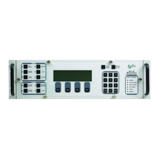
Page 24: Rcs20 Switching System Components
RCS20 M:N Redundancy Switch Rev. 14 Introduction MN-RCS20 RCS20 Switching System Components The RCS20 is comprised of three separate units that make up the switching system: • The Redundancy Control Unit (RCU20); • The Digital Data Switch (DDS20); • The Intermediate Frequency Switch (IFS20). -
Page 25: Digital Data Switch (Dds20) Configurations
RCS20 M:N Redundancy Switch Rev. 14 Introduction MN-RCS20 1.3.2 Digital Data Switch (DDS20) Configurations The DDS20 provides all of the data interconnections between the online and backup modems. The DDS20 also provides buffering of terrestrial data signals to backup modulators allowing ‘hot-standby’... -
Page 26: Universal Dds20
RCS20 M:N Redundancy Switch Rev. 14 Introduction MN-RCS20 1.3.2.1 Universal DDS20 The Universal DDS20 has nine available slots supporting up to a 1:9 or 2:8 configuration. Figure 1-4 Universal DDS20 Digital Data Switch – Front Panel Figure 1-5 Universal DDS20 Digital Data Switch – Back Panel... -
Page 27: Dds20-Asi-M Or Dds20-G703-M (Modulator-Only)
RCS20 M:N Redundancy Switch Rev. 14 Introduction MN-RCS20 1.3.2.2 DDS20-ASI-M or DDS20-G703-M (Modulator-only) The DDS20-ASI-M or G703-M is a modulator-only configuration. Figure 1-6 DDS20 ASI or G703-M Digital Data Switch – Front Panel Figure 1-7 DDS20 ASI or G703-M Digital Data Switch – Back Panel... -
Page 28: Dds20-Asi Or Dds20-G.703-D (Demodulator-Only)
RCS20 M:N Redundancy Switch Rev. 14 Introduction MN-RCS20 1.3.2.3 DDS20-ASI or DDS20-G.703-D (Demodulator-only) The DDS20-ASI-D or DDS20-G.703-D is a demodulator-only configuration. Figure 1-8 DDS20-ASI-D or DDS20-G.703-D Digital Data Switch – Front Panel Figure 1-9 DDS20-ASI-D or DDS20-G.703-D Digital Data Switch – Back Panel... -
Page 29: Dds20-Gige (10/100/1000 Gigabit Ethernet) Backup Switch
RCS20 M:N Redundancy Switch Rev. 14 Introduction MN-RCS20 1.3.2.4 DDS20-GigE (10/100/1000 Gigabit Ethernet) Backup Switch The DDS20-GigE Backup Switch configuration supports the DMD20, DMD50, DM240 and DD240 products. The Ethernet switch can support up to a 1:9 system. Figure 1-10 DDS20-GigE Backup Switch – Front Panel Figure 1-11 DDS20-GigE Backup Switch –... -
Page 30: Intermediate Frequency Switch (Ifs20) Configurations
RCS20 M:N Redundancy Switch Rev. 14 Introduction MN-RCS20 1.3.3 Intermediate Frequency Switch (IFS20) Configurations The IFS20 Intermediate Frequency Switch interfaces the IF signals of the modems with the Earth Station IF system and provides backup switching. The RCU20 can be configured with or without the IFS20. -
Page 31: L-Band Ifs20 (Transmit Only)
RCS20 M:N Redundancy Switch Rev. 14 Introduction MN-RCS20 1.3.3.2 L-Band IFS20 (Transmit Only) This IFS20 configuration is used for L-Band transmit only systems. Figure 1-14 L-Band (Transmit Only) IFS20 Intermediate Frequency Switch – Front Panel Figure 1-15 L-Band (Transmit Only) IFS20 Intermediate Frequency Switch – Back Panel... -
Page 32: L-Band Ifs20 (Transmit & Receive)
RCS20 M:N Redundancy Switch Rev. 14 Introduction MN-RCS20 1.3.3.3 L-Band IFS20 (Transmit & Receive) This IFS20 configuration is used for L-Band transmit and receive systems. Figure 1-16 L-Band (Transmit & Receive) IFS20 Intermediate Frequency Switch – Front Panel Figure 1-17 L-Band (Transmit & Receive) IFS20 Intermediate Frequency Switch – Back Panel... - Page 33 Chapter 2. Installation Overview This chapter provides unpacking instructions, and instructions for installing an RCS20 M:N Redundancy Switch into a Satellite Modem system with cabling configurations for up to nine channels and nine transponders. The RCS20 organizes the modems connected to the switch according to satellite communications channels.
-
Page 34: Installation
Any cables ordered in addition to those listed above may arrive separately. 2.2.1 Test Data Sheet Each RCS20 M:N Redundancy Switch system is shipped with a Test Data Sheet. This report contains information on the results of the Switch quality control testing. The report also includes information pertaining to the system settings that were made at the factory. -
Page 35: Removal And Assembly
The RCS20 is designed so that it can be mounted in a standard 19-inch rack. The RCS20 is 5¼”, 3 Rack Units (3RU) high and must be mounted on the front of a rack with the front panel facing forward The DDS20 is 8¾”... -
Page 36: Storage
In addition, the RCS20 requires a minimum of 1¾” (1 RU) of clearance on top of the unit. If the Switch is mounted on slide mounts, the cables must be of sufficient length to allow the units to be pulled forward on the mounts. - Page 37 RCS20 M:N Redundancy Switch Rev. 14 Installation MN-RCS20 Never apply power to the slide out power supply modules unless they are firmly seated in the RCU20, as there is a potential shock hazard at the AC/DC Converter within the module Turn the unit on by switching both AC power switches (located above the power entry connectors at the rear of the RCU20) to the on position.
- Page 38 RCS20 M:N Redundancy Switch Rev. 14 Installation MN-RCS20 Notes: 2–6...
-
Page 39: Theory Of Operation
Chapter 3. Theory of Operation Overview This chapter provides additional basic information on the RCU20, DDS20, and IFS20 hardware and internal operation. RCU20 Major Assemblies The RCU20 Redundancy Control Unit contains the modules that control and monitor the operation of the M:N Switch System. The RCU20 is composed of the following major assemblies and components: •... -
Page 40: Front Panel
The Bank Control Module provides connection to auxiliary equipment. See Section 5.2.3.3. 3.2.8 RCU20 Back Panel Tthe RCS20 contains the plug-in slots for the Interface Control Module, the Clock Distribution Modules, Bank Control Modules and Ethernet modules. Also contained in the back panel are the two AC fuses and power receptacles. -
Page 41: If Switch Relays
RCS20 M:N Redundancy Switch Rev. 14 Theory of Operation MN-RCS20 The IFS20 has no internal power supply. It receives its DC power from the RCU20 through the cable that connects to J35. The IFS20 internal connectors are SMB-type. The major parts of the IFS20 are: •... -
Page 42: Dds20 Back Panel
The DDS20 back panel contains the electrical connections. RCS20 Channel Definitions The RCS20 organized the modems connected to the switch according to satellite communications channels. These channels are labeled on the DDS20 and IFS20 panels, and are defined as follows:... -
Page 43: User Interfaces
Operation of the RCS20 consists of controlling the unit operating parameters and monitoring status and responses via one of the following control interfaces: • Front Panel Interface • Remote Port Interface • Terminal Interface Any of these methods may be used separately or together to monitor and control the RCS20. 4–1... -
Page 44: Front Panel Interface
LCD Display. Switch Control. This group of keys is used to control the RCS20 and SWITCH decide which menu tree is displayed on the front panel. -
Page 45: Modem Control Keys
4.2.1.4 MODEM MONITOR Pressing this key brings up a series of menus on the LCD that allow the monitoring of status parameters for modems connected to the RCS20. This feature is presently not implemented on the RCS20. 4.2.1.5 MODEM TEST Pressing this key brings up a series of menus on the LCD that allow testing of the modems connected to the RCS20. -
Page 46: Reset Alarms Key
Green Terminal port or the Remote M&C port 4.2.6 Numeric Keypad This group of keys is used to perform various functions for the RCS20 and connected modems. Table 4-3 describes the function of these keys. Table 4-3. Numeric Keypad Function... -
Page 47: Soft Keys (S1 - S4)
The following keys, when pressed, control the RCS20 and decide which of the menu trees is displayed on the LCD front panel display. 4.2.8.1 SWITCH CONFIG SWITCH Pressing this key brings up a series of menus on the LCD that allow control of the RCS20 switch configuration parameters. 4.2.8.2 SWITCH CONFIG SYSTEM Pressing this key brings up a series of menus on the LCD that allow control of the RCS20 system, M&C, and communication parameters. -
Page 48: Moving To The Next Screen In A Menu Tree
RCS20 M:N Redundancy Switch Rev. 14 User Interfaces MN-RCS20 Editing a configuration parameter value is accomplished in one of several ways. If the parameter is numerical, the desired value should be entered from the numeric keys. Occasionally, the numeric values can be incremented and decremented by pressing soft keys labeled ‘UP’ and ‘DOWN’... -
Page 49: Front Panel Screens
RCS20 M:N Redundancy Switch Rev. 14 User Interfaces MN-RCS20 Front Panel Screens There are four menu trees used to control the RCS20: • CONFIG SWITCH • CONFIG SYSTEM • MONITOR/ALARMS • TEST These menu trees and their functions are discussed in the subsections that follow. -
Page 50: Config Switch Menu Tree
TOG MODE NEXT This screen allows the user to assign connections to the channels. The RCS20 must be programmed with satellite channel numbers used for redundancy protection. Channel 0 is the dedicated backup, and Channel 9 may either be prime or backup. Channels 1 to 8 are dedicated backups. -
Page 51: Modem Addresses
RCS20 M:N Redundancy Switch Rev. 14 User Interfaces MN-RCS20 4.3.1.2 MODEM ADDRESSES MODEM ADDRESSES USE KEYPAD 101 102 103 104 105 106 107 108 109 110 <--- ---> NEXT This screen allows the user to program the remote addresses of each modem connected to the redundancy system. -
Page 52: Modem Channel Connection Test
<START> NEXT This screen allows the user to test communication channels between the RCS20 and all modems connected to the system. The ** indicates communication is in progress, and will move between all configured channels before the test is complete. -
Page 53: Modem 9 / Backup 2 Configuration
RCS20 M:N Redundancy Switch Rev. 14 User Interfaces MN-RCS20 4.3.1.4 MODEM 9 / BACKUP 2 CONFIGURATION MODEM 9 / <BACKUP> 2 CONFIGURATION MODEM9 MODE : BACKUP MODE NEXT This screen allows the user to select the mode operation for Channel 9. The Channel 9 Modem can operate as a prime or backup. -
Page 54: Modem 9 / Backup 2 Mode
RCS20 M:N Redundancy Switch Rev. 14 User Interfaces MN-RCS20 4.3.1.4.1 MODEM 9 / BACKUP 2 MODE MODEM 9 / <BACKUP> 2 CONFIGURATION MODE: BACKUP <BACKUP> <PREEMPT> <TRAFFIC> <RETURN> This screen allows the user to select the mode operation for Channel 9. The channel 9 modem can operate as a prime, a preemptable prime, or a dedicated backup. -
Page 55: Backup Mode Configuration
RCS20 M:N Redundancy Switch Rev. 14 User Interfaces MN-RCS20 4.3.1.5 BACKUP MODE CONFIGURATION <BACKUP> MODE CONFIGURATION BACKUP 1 <BACKUP> MODE: MANUAL BACKUP 2 <BACKUP> MODE: MANUAL BU1 MODE BU2 MODE NEXT This screen displays the mode of backup operation for Backup Channels 1 and 2. If Channel 9 is configured as a prime channel, the selections for Backup Channel 2 will be unavailable. -
Page 56: Backup Mode 1 Select
RCS20 M:N Redundancy Switch Rev. 14 User Interfaces MN-RCS20 4.3.1.5.1 BACKUP MODE 1 SELECT <BACKUP> MODE CONFIGURATION BACKUP 1 <BACKUP> MODE: MANUAL <MANUAL> <NON-REV> <REVERT> <RETURN> This screen allows the user to select the mode of backup operation for Backup Channel 1 (Channel 0). -
Page 57: Backup Mode 2 Select
RCS20 M:N Redundancy Switch Rev. 14 User Interfaces MN-RCS20 4.3.1.5.2 BACKUP MODE 2 SELECT <BACKUP> MODE CONFIGURATION BACKUP 2 <BACKUP> MODE: MANUAL <MANUAL> <NON-REV> <REVERT> <RETURN> This screen allows the user to select the mode of backup operation for Backup Channel 2 (Prime Channel 9), if this channel is configured as a backup channel. -
Page 58: Modem Switching Style
Pressed in conjunction with S1 ( ) to position a blinking cursor to select the switching style. ® DoubleTalk is licensed from Raytheon Applied Signal Technology. ® DoubleTalk is a registered trademark of Raytheon Applied Signal Technology. ® Carrier-in-Carrier is a registered trademark of Comtech EF Data. 4–16... -
Page 59: Auto Mode Backup Assignment Summary
Channel 1. This line will have the label BU1-MANUAL if Backup Channel 1 is configured for manual backup. Note that the automatic backup assignments can be programmed into the RCS20 while the backup channel is in manual mode; the auto backup assignments will then become active when the backup channel is placed into auto-revertive or auto-non-revertive backup mode. - Page 60 RCS20 M:N Redundancy Switch Rev. 14 User Interfaces MN-RCS20 The BU2 Line shows the prime channels that are programmed for automatic backup by Backup Channel 2. This line will have the label BU2-AUTO if Backup Channel 2 is configured for auto- revertive or auto-non-revertive backup.
-
Page 61: Auto Mode Backup 1 Assignment Program
TOG MODE RETURN The Auto Mode Backup 1 Assignment Program Subscreen allows the user to program the RCS20 Backup Channel 1 to provide automatic switching for any or all of the prime channel modems. The following letter codes indicate backup assignment information for Backup Channel 1 on this screen: •... -
Page 62: Auto Mode Backup 2 Assignment Program
TOG MODE RETURN This subscreen allows the user to program the RCS20 Backup Channel 2 to provide automatic switching for any or all of the prime channel modems. The following letter codes indicate backup assignment information for Backup Channel 2 on this screen: •... -
Page 63: Backup Assignments, Priorities
---> RETURN This subscreen allows the user to program the RCS20 with priorities for each prime channel. A 1 indicates the highest priority channel and a 9 indicates the lowest priority channel. The highest priority prime channel for each backup channel will have its modulator and/or demodulator placed in hot standby. -
Page 64: Ifs20L Demod Bkup Assignment Summary
RCS20 M:N Redundancy Switch Rev. 14 User Interfaces MN-RCS20 4.3.1.8 IFS20L DEMOD BKUP ASSIGNMENT SUMMARY AUTO MODE <BACKUP> ASSIGNMENT SUMMARY MODEM BU1-DEMOD : A BU2-DEMOD : E SET BU1 SET BU2 NEXT This screen is used to assign the channels. Channel assignments depend on whether the default or Combined IFL configuration is in use. -
Page 65: Learn/Backup Test Configuration
RCS20 M:N Redundancy Switch Rev. 14 User Interfaces MN-RCS20 4.3.1.9 LEARN/BACKUP TEST CONFIGURATION LEARN/BACKUP TEST CONFIGURATION (*=ConfigChanged, F=BackupTestFailed) MODEM LEARNED :** md md md md md md md md md BU1 TEST BU2 TEST LEARN TEST COPY NEXT This screen displays modem learn state and backing test status. The status may be one of the following: •... -
Page 66: Learn Test Configuration
RCS20 M:N Redundancy Switch Rev. 14 User Interfaces MN-RCS20 4.3.1.9.1 LEARN TEST CONFIGURATION LEARN/BACKUP TEST CONFIGURATION <ENT> to accept, <CLR> to abort. LEARN MODEM #: DOWN CANCEL This screen allows the user to select modems to learn. Label Function Press to cycle up through the modem test options (ALL, MODEM0, MODEM1 - MODEM9). -
Page 67: Backup Test Configuration
RCS20 M:N Redundancy Switch Rev. 14 User Interfaces MN-RCS20 4.3.1.9.2 BACKUP TEST CONFIGURATION BACKUP TEST CONFIGURATION <ENT> to accept, <CLR> to abort. TEST MODEM #: DOWN CANCEL This screen allows the user to perform backup tests on a selected modem. -
Page 68: Copy Modem Configuration
RCS20 M:N Redundancy Switch Rev. 14 User Interfaces MN-RCS20 4.3.1.9.3 COPY MODEM CONFIGURATION COPY MODEM CONFIGURATION <ENT> to accept, <CLR> to abort. COPY FROM : MODEM1 COPY TO MODEM8 CURSOR DOWN CANCEL This screen allows the user to copy configurations between (from/to) modems. -
Page 69: Mod Fault Delay
RCS20 until the timer reaches fault delay seconds. The fault delay can be from 0.0 seconds to 199.9 seconds for each of the modulators (each modulator may be set to a different time delay if desired). -
Page 70: Demod Fault Delay
RCS20 until the timer reaches fault delay seconds. The fault delay can be from 0.0 seconds to 199.9 seconds for each of the demodulators (each demodulator may be set to a different time delay if desired). -
Page 71: Demod Aqu Delay
This screen allows the user to set the length of time (in seconds) for each prime channel on the RCS20. The fault delays for a demodulator are used to debounce the demodulator faults, thus if a demodulator does not acquire, a timer is started and the failure will not be recognized by the RCS20 until the timer reaches fault delay seconds. -
Page 72: Force Manual Backup
RCS20 M:N Redundancy Switch Rev. 14 User Interfaces MN-RCS20 4.3.1.9.7 FORCE MANUAL BACKUP FORCE <MANUAL> BACKUP MODEMS: BU1: BU2: M=MOD, D=DEMOD, U=MODEM SET BU1 SET BU2 NEXT This screen allows the user to switch prime channels into backup manually. Backup Channel 1 must be in manual mode to force prime channels into backup. -
Page 73: Force Manual Backup 2
RCS20 M:N Redundancy Switch Rev. 14 User Interfaces MN-RCS20 4.3.1.9.7.1 FORCE MANUAL BACKUP 1 FORCE <MANUAL> <BACKUP> 1 FORCE <BACKUP> 1 -> MODULATOR: FORCE <BACKUP> 1 -> DEMODULATOR: ENTER MOD ONLY FOR MODEM TYPE SWITCHING DEMOD RETURN This subscreen allows the user to switch prime channels to backup Channel 1 manually. Backup Channel 1 must be in manual mode for to force prime channels into backup. - Page 74 RCS20 M:N Redundancy Switch Rev. 14 User Interfaces MN-RCS20 4.3.1.9.7.2 FORCE MANUAL BACKUP 2 FORCE <MANUAL> <BACKUP> 2 FORCE <BACKUP> 2 -> MODULATOR: FORCE <BACKUP> 2 -> DEMODULATOR: ENTER MOD ONLY FOR MODEM TYPE SWITCHING DEMOD RETURN This subscreen allows the user to switch prime channels to backup Channel 2 manually. Channel 9 must be configured as Backup Channel 2, and Backup Channel 2 must be in manual mode to force prime channels into backup.
-
Page 75: Config System Menu Tree
RCS20 M:N Redundancy Switch Rev. 14 User Interfaces MN-RCS20 4.3.2 CONFIG SYSTEM Menu Tree 4.3.2.1 CONTROL MODE CONFIGURATION CONTROL MODE CONFIGURATION CONTROL MODE: FRONT PANEL <FT PANEL> <TERM> <COMPUTER> NEXT This screen allows the user to modify the control mode. The Control Mode may be one of the following: •... -
Page 76: Terminal Port Configuration
RCS20 M:N Redundancy Switch Rev. 14 User Interfaces MN-RCS20 4.3.2.2 TERMINAL PORT CONFIGURATION TERMINAL PORT CONFIGURATION TERMINAL BAUD RATE : 19200 TERMINAL EMULATION : VT 100 BAUD EMUL NEXT This screen displays both the Terminal Baud Rate and the Terminal Emulation Type, and allows the user to cycle to Subscreens to change the configurations. -
Page 77: Terminal Port Baud Rate
9600 2400 CANCEL This subscreen allows the user to modify the RCS20 terminal port baud rate. Programming steps: 1. Press <19200>, <9600>, or <2400> to select the desired terminal port baud rate. The switch parameter table will be updated immediately. -
Page 78: Terminal Port Emulation
VT100 WYSESO RETURN This subscreen allows the user to modify the RCS20 terminal port terminal emulation. Programming steps: 1. Press <ADDS VP>, <VT 100>, or <WYSE 50> to select the desired terminal port emulation type. The switch parameter table will be updated immediately. -
Page 79: Remote Port Configuration
RCS20 M:N Redundancy Switch Rev. 14 User Interfaces MN-RCS20 4.3.2.3 REMOTE PORT CONFIGURATION REMOTE PORT CONFIGURATION RCU20 REMOTE PORT BAUD RATE : 1200 RCU20 REMOTE PORT ADDRESS : 32 RCU20 REMOTE PORT PROTOCOL : RLLP BAUD ADDR PROTOCOL NEXT This screen displays the Remote Port Baud Rate, the Remote Port Address, and the Terminal Emulation Type, and allows the user to cycle to Subscreens to change the configurations. -
Page 80: Remote Port Baud Rate Configuration
RCS20 M:N Redundancy Switch Rev. 14 User Interfaces MN-RCS20 4.3.2.3.1 REMOTE PORT BAUD RATE CONFIGURATION REMOTE PORT BAUD RATE CONFIGURATION RCU20 REMOTE PORT BAUD RATE : 1200 1200 2400 4800 NEXT This subscreen allows the user to modify the Remote Port Baud Rate. -
Page 81: Remote Port Address
This subscreen allows the user to modify the RCS20 remote port baud address. Programming steps: 1. Use the numeric keypad to enter the desired multi-drop address for the RCS20. Valid addresses are 32 through 255. 2. Press <CLR> or <NEXT> to abort programming (no switch parameters will be changed). -
Page 82: Remote Port Protocol Configuration
RCS20 M:N Redundancy Switch Rev. 14 User Interfaces MN-RCS20 4.3.2.3.3 REMOTE PORT PROTOCOL CONFIGURATION MODEM PORT PROTOCOL CONFIGURATION MODEM MODEM PORT PROTOCOL : 9600 BAUD NEXT This subscreen allows the user to modify the modem remote port communication protocol. The remote port protocol determines the binary format for communication between the RCU20 and all modems connected to the RCU20. -
Page 83: Modem Port Configuration
RCS20 M:N Redundancy Switch Rev. 14 User Interfaces MN-RCS20 4.3.2.4 MODEM PORT CONFIGURATION MODEM PORT CONFIGURATION RCU20 MODEM PORT BAUD RATE : 9600 BAUD NEXT This screen displays the Remote Port Baud Rate and allows the user to cycle to Subscreens to change the configurations. -
Page 84: Modem Port Baud Rate Configuration
RCS20 M:N Redundancy Switch Rev. 14 User Interfaces MN-RCS20 4.3.2.4.1 MODEM PORT BAUD RATE CONFIGURATION MODEM PORT BAUD RATE CONFIGURATION RCU20 MODEM PORT BAUD RATE : 1200 9600 19200 38400 57600 This subscreen allows the user to modify the Modem Port Baud Rate. -
Page 85: Key Click Configuration
RCS20 M:N Redundancy Switch Rev. 14 User Interfaces MN-RCS20 4.3.2.5 KEY CLICK CONFIGURATION KEY CLICK CONFIGURATION KEY CLICK : NEXT This screen allows the user to turn on/off the audible key click that is heard with every key press on the front panel. -
Page 86: Time / Date Configuration
RCS20 M:N Redundancy Switch Rev. 14 User Interfaces MN-RCS20 4.3.2.6 TIME / DATE CONFIGURATION TIME / DATE CONFIGURATION DATE : 01 JAN 04 TIME : 00:00:00 DATE TIME NEXT This screen displays the current real-time clock and date. The date and time are in the following format: •... -
Page 87: Set Date
DATE : 01 JAN 04 <--- ---> DOWN This subscreen allows the user to configure the real-time clock date for the RCS20. Programming steps: Press to move the blinking cursor to the day, month, or year. 2. Press <UP> to increase the value of the day, month or year (at the location of the blinking cursor), press <DOWN>... -
Page 88: Set Time
TIME : 09:l5:59 <--- ---> DOWN This subscreen allows the user to configure the real-time clock function for the RCS20. Programming steps: 1. Press to move the blinking cursor the hour, minute, or second. 2. Press <UP> to increase the value of the hour, minute, or second (at the location of the blinking cursor). -
Page 89: Lcd Contrast Adjustment
RCS20 M:N Redundancy Switch Rev. 14 User Interfaces MN-RCS20 4.3.2.7 LCD CONTRAST ADJUSTMENT LCD CONTRAST ADJUSTMENT +----------------------------+ : ABCDEFGHIJKLMNOPQRSTUVWXYZ : +----------------------------+ DOWN NEXT This screen allows the user to adjust the contrast of the characters on the LCD screen. The switch parameter table is immediately updated upon any changes. -
Page 90: Lcd Backlight Timeout
RCS20 M:N Redundancy Switch Rev. 14 User Interfaces MN-RCS20 4.3.2.8 LCD BACKLIGHT TIMEOUT LCD BACKLIGHT TIMEOUT USE KEYPAD TIMEOUT : 60 SECONDS NEXT Whenever a button is pressed on the front panel, the LCD backlight illuminates. This screen allows the user to adjust the length of time (in seconds) between the last key press and the LCD backlight extinguishing. -
Page 91: Bank Control Configuration
RCS20 M:N Redundancy Switch Rev. 14 User Interfaces MN-RCS20 4.3.2.9 BANK CONTROL CONFIGURATION B A N K C O N T R O L C O N F I G U R A T I O N D I S A B L E I F S : N O... -
Page 92: Ifs Bank Controller
RCS20 M:N Redundancy Switch Rev. 14 User Interfaces MN-RCS20 4.3.2.9.1 IFS BANK CONTROLLER IFS BANK CONTROLLER DISABLE IFS: TOG MODE RETURN This screen allows the user to disable IFS. Label Function TOG MODE Press to toggle between NO and YES. -
Page 93: Dds Bank Controller
RCS20 M:N Redundancy Switch Rev. 14 User Interfaces MN-RCS20 4.3.2.9.2 DDS BANK CONTROLLER DDS BANK CONTROLLER DISABLE DDS: TOG MODE RETURN This screen allows the user to disable DDS. Label Function TOG MODE Press to toggle between NO and YES. -
Page 94: Combine Ifl (Ifs L-Band Demodulator Only)
RCS20 M:N Redundancy Switch Rev. 14 User Interfaces MN-RCS20 4.3.2.9.3 COMBINE IFL (IFS L-Band Demodulator Only) C O M B I N E D E M O D I F L C O M B I N E I F L :... -
Page 95: Carrier-In-Carrier Modems
In Carrier and Carrier switching mode the RCS20 does NOT support Independent Modulator and demodulator Switching as seen in Section 4.3.1.6 (Modem Switching Style). Also, on the RCS20 you will want to set the Mod and Demod Fault Delay (Sections 4.3.1.9.4 and 4.3.1.9.5) to 5 seconds minimum. You will also need to set the Demod Acquisition Delay (Section 4.3.9.6) to a minimum of... -
Page 96: Cnc Switching
RCS20 M:N Redundancy Switch Rev. 14 User Interfaces MN-RCS20 Label Function Press to change CnC Switching Mode. NEXT Press to cycle to next screen. Press <CLR> to abort programming (no switch parameters will be Numeric changed) and cycle back to the BANK CONTROL CONFIGURATION... -
Page 97: Software/Firmware Versions
: F0XXXXXX SOFTWARE VERSION NUMBER : X.X NEXT This screen displays the current software version number and firmware part number for the RCS20. No switch parameters are programmed from this screen. Label Function NEXT Press to cycle to the next screen. -
Page 98: Reference Distribution Configuration
The line directly above the FALLBACK Line displays the current source with '***'. This line will display the message NO RDM PRESENT if the RDM is not installed in the RCS20 system. Programming steps: 1. Press <FALL> to cycle to the RDM FALLBACK CONFIGURATION Screen for fallback programming configuration. -
Page 99: Rdm Fallback Configuration
RCS20 M:N Redundancy Switch Rev. 14 User Interfaces MN-RCS20 4.3.2.9.8 RDM FALLBACK CONFIGURATION RDM INTERNAL REFERENCE CONFIGURATION FALLBACK : EXTA ONLY TOG MODE RETURN This screen allows the user to configure the fallback programming for the optional Reference Distribution Module (RDM). The RDM has two reference inputs (EXTA, EXTB) and an internal frequency source (INT). - Page 100 RCS20 M:N Redundancy Switch Rev. 14 User Interfaces MN-RCS20 4.3.2.9.9 RDM FALLBACK CONFIGURATION RDM INTERNAL REFERENCE CONFIGURATION INTERNAL FREQ : 10.0 MHZ TOG MODE RETURN This screen allows the user to configure the RDM Internal Reference Frequency. The internal frequencies may be one of the following: •...
-
Page 101: Modem Service Mode
RCS20 M:N Redundancy Switch Rev. 14 User Interfaces MN-RCS20 4.3.2.9.10 MODEM SERVICE MODE MODEM SERVICE MODE (N = Normal, S = Service) BACKUP : MODEM SERVICE: N SERVICE NEXT This screen displays the modem service mode: • N - Normal •... -
Page 102: Modem Service Mode Selection
RCS20 M:N Redundancy Switch Rev. 14 User Interfaces MN-RCS20 4.3.2.9.11 MODEM SERVICE MODE SELECTION MODEM SERVICE MODE BACKUP : MODEM SERVICE: N TOG MODE RETURN This screen is the actual location where the user can configure the Modem Service Mode. -
Page 103: Ifs20-L Demod Bkup Assignment Summary
RCS20 M:N Redundancy Switch Rev. 14 User Interfaces MN-RCS20 4.3.2.9.12 IFS20-L DEMOD BKUP Assignment Summary Go to the CONFIG SWITCH Menu. Toggle to the IFS20L DEMOD BKUP ASSIGNMENT SUMMARY Screen. Press the Button S1 (SET BU1) on the Front Panel. The IFS20L DEMOD BKUP ASSIGNMENT PROGRAM Screen will appear. -
Page 104: Monitor/Alarms Menu Tree
RCS20 M:N Redundancy Switch Rev. 14 User Interfaces MN-RCS20 4.3.3 MONITOR/ALARMS Menu Tree 4.3.3.1 EXPANSION SLOT MONITOR EXPANSION SLOT MONITOR SLOT 0: (EMPTY) SLOT 1: USER INTERFACE SLOT 2: BANK CONTROL:(IFS20A, DDS20) SLOT 3: (EMPTY) SLOT 4: (EMPTY) SLOT 5:... -
Page 105: Mod / Demod Fault Monitor
RCS20 M:N Redundancy Switch Rev. 14 User Interfaces MN-RCS20 4.3.3.2 MOD / DEMOD FAULT MONITOR MOD / DEMOD FAULT MONITOR BACKUP : B2 B1 MODEM CONNECT:md md md md md md md md md md FAULT :FF ?? FF ?? FF FF ?? ?? FF FF... -
Page 106: Events
DOWN NEXT This screen displays the stored events due to manual or automatic backups on the RCS20. Detailed descriptions of the causes of failed backups are also stored. Events are stored and sorted by the time and date of the action causing the event to be stored. The earliest event will be the first stored event, and the latest event will be the last stored event. -
Page 107: Switch Major Alarms 1
MAJOR ALARM lamp nor on the ALARM connector at the rear of the RCS20. The RAM/ROM alarm indicates a failure of the RCS20 internal memory. The BACKUP UNAVAILABLE alarm indicates that a prime channel modem has failed, but there was no backup channel modem available for backup, causing prime channel traffic to be dropped. -
Page 108: Switch Major Alarms 2
RCS20 M:N Redundancy Switch Rev. 14 User Interfaces MN-RCS20 4.3.3.6 SWITCH MAJOR ALARMS 2 SWITCH MAJOR ALARMS MASK BACKUP1 MOD ERROR : PASS BACKUP1 DEMOD ERROR : FAIL BACKUP2 MOD ERROR : PASS BACKUP2 DEMOD ERROR : FAIL TOG MODE NEXT These screens display additional major alarms. -
Page 109: Switch Minor Alarms 1
TOG MODE NEXT These screens display the RCS20 minor alarms, and allow the user to mask these alarms. When an alarm is masked, the error will not be reported on the front panel MINOR ALARM Lamp or on the ALARM connector at the rear of the RCU20. The POWER SUPPLY 1 PRESENT Alarm indicates that slide-in Power Supply Module 1 is fully seated in the RCU20. -
Page 110: Switch Minor Alarms 2
RCS20 M:N Redundancy Switch Rev. 14 User Interfaces MN-RCS20 4.3.3.8 SWITCH MINOR ALARMS 2 SWITCH MINOR ALARMS MASK COMMUNICATIONS : PASS PRIME MODEM STATUS : FAIL BACKUP MODEM STATUS : PASS PRIME MODEM CONFIGURATION : FAIL TOG MODE NEXT These screens display minor alarms. -
Page 111: Test Menu Tree
RCS20 M:N Redundancy Switch Rev. 14 User Interfaces MN-RCS20 4.3.4 TEST Menu Tree 4.3.4.1 SWITCH SYSTEM TESTS SWITCH SYSTEM TESTS SYSTEM COMMUNICATION TEST MODEM PARAMETER COMPATIBILITY TEST LAMP TEST COMM PARM LAMP NEXT This screen allows execution of the following tests: •... -
Page 112: Modem Channel Connection Test
<START> RETURN This screen allows the user to test communication channels between the RCS20 and all modems connected to the system. If the test fails for one or more channels, check the parameter entries for screens Config 0 and Config 1. The '*' indicates communication in progress, and will move between all configured channels before the test is complete. -
Page 113: Modem Parameter Compatibility Test
RCS20 M:N Redundancy Switch Rev. 14 User Interfaces MN-RCS20 4.3.4.1.2 MODEM PARAMETER COMPATIBILITY TEST MODEM PARAMETER COMPATIBILITY TEST MODEM BU1-MANUAL:md md md md md md md md md md BU2-MANUAL:md md md md md md md md md md PASSED :YY YY YY YY YY YY NN YY YY YY <START>... -
Page 114: Lamp Test
RCS20 M:N Redundancy Switch Rev. 14 User Interfaces MN-RCS20 4.3.4.1.3 LAMP TEST LAMP TEST PRESS THE ‘START SOFTKEY TO ILLUMINATE ALL FRONT PANEL LEDS FOR 5 SECONDS. <START> RETURN This screen allows the user to test all LED lamps on the front panel of the RCU20 for five seconds. -
Page 115: Switch System Tests Screen 2
RCS20 M:N Redundancy Switch Rev. 14 User Interfaces MN-RCS20 4.3.4.2 SWITCH SYSTEM TESTS Screen 2 SWITCH SYSTEM TESTS REMOTE PORT TEST REMOTE NEXT REMOTE PORT TEST - the unit sends the ASCII characters ‘TEST’ to the remote port to test communications. -
Page 116: Remote Port Test
This screen allows the user to send an ASCII test string out of the remote port. Programming steps: 1. Press <TEST> to send an ASCII string. The RCS20 will output ASCII characters ‘Test’ via remote port each time <TEST> is pressed. -
Page 117: Remote Interface
Remote Interface 4.4.1 Host Computer Remote Communications The RCS20 has a dedicated RS-485 serial control port (Remote Port) for use with computer controlled remote monitor and control systems. The Remote Port is a 9-Pin female ‘D’ sub connector J3 located at the rear of the unit on the Switch Interface plug in module. The pinouts for the remote port are listed in Section 5. -
Page 118: Terminal Port Control
MN-RCS20 Terminal Port Control The RCS20 has a dedicated RS-232 serial port (Terminal Port) for use with a separate terminal or computer running a terminal emulation program. The Terminal Port is a 9-Pin female ‘D’ sub connector J2 located at the rear of the unit on the Switch Interface plug in module. The pinouts for the remote port are listed in Section 5. - Page 119 RCS20 M:N Redundancy Switch Rev. 14 User Interfaces MN-RCS20 1.Main Menu 11.Ch 0 Config :BACKUP 21.Force Mod BU1:0 2.Control Mode:FT PANEL 12.Ch 9 Config :TRAFFIC 22.Force Dmd BU1:0 3.Remote Mode :RLLP 13.BU1 BU Mode :MANUAL 23.Force Mod BU2:0 4.Remote Addr :32 14.BU2 BU Mode...
- Page 120 RCS20 M:N Redundancy Switch Rev. 14 User Interfaces MN-RCS20 1.Main Menu Expansion 0:(EMPTY) Software Release:5.9 2.Control Mode:FT PANEL Expansion 1:USER I/O Firmware P/N :F03469AS 3.Remote Mode :RLLP Expansion 2:BANK CTL Date :03JAN00 4.Remote Addr :32 Expansion 3:(EMPTY) Time :04:08:15 5.Remote Baud :9600...
- Page 121 RCS20 M:N Redundancy Switch Rev. 14 User Interfaces MN-RCS20 1.Main Menu 21.Reset Alarms 2.Control Mode:FT PANEL 3.Remote Mode :RLLP 4.Remote Addr :32 5.Remote Baud :9600 ------------------------------- ALARMS -------------------------- ------------ MAJOR ALARMS MASK LATCH MINOR ALARMS MASK LATCH 30.RAM/ROM PASS PASS 40.PS1 Present...
- Page 122 RCS20 M:N Redundancy Switch Rev. 14 User Interfaces MN-RCS20 1.Main Menu 11.Delete One Entry u.Cursor UP 2.Control Mode:FT PANEL 12.Delete All Entries d.Cursor DOWN 3.Remote Mode :RLLP 13.Clear Event LED U.Page UP 4.Remote Addr :32 D.Page DOWN 5.Remote Baud :9600 h(H).Home...
-
Page 123: Electrical Interfaces
Chapter 5. Electrical Interfaces Overview This chapter describes the interfaces available on the RCS20 M:N Redundancy Switch System (Figure 5-1). All RCS20 connections (including the RCU20 and various configurations of the DDS20 and IFS20) are made to labeled connectors located on the back panel of the RCU (Figure 5-2). -
Page 124: Rcu20 Back Panel Connectors
5.2.1 Slide-Out Redundant Power Supply/Switch Modules Dangerous AC voltages exist inside of the RCS20 when either one of the AC Plug-in Switch Modules are enabled or plugged in. Do not remove cover when AC power is applied. Remove power cord from AC modules if top cover needs to be removed. -
Page 125: Expansion Slots
RCS20. The RDM automatically switches between EXT A, EXT B or Internal References based upon onboard Clock Activity Detect circuits. -
Page 126: J1 | Ext A In (External Input A)
RCS20 M:N Redundancy Switch Rev. 14 Electrical Interfaces MN-RCS20 Figure 5-4 Reference Distribution Module Jumper Settings Set the jumpers according to the following table to get the required termination impedance: Termination Impedance (Ohms) Pins 1 and 2 Shorted Pins 1 and 2 Shorted 50Ω... -
Page 127: J2 | Ext B In (External Input B)
RCS20 M:N Redundancy Switch Rev. 14 Electrical Interfaces MN-RCS20 5.2.3.1.2 J2 | EXT B IN (External Input B) 50, 75, 510 Ohms (Jumper-Selectable) Impedance 1.25, 2.5, 5.0 and 10.0 MHz Frequency • High-Level 2 to 5 Volt Input Level Specification •... -
Page 128: Board Outline
Rev. 14 Electrical Interfaces MN-RCS20 5.2.3.1.7 Board Outline • RCS20 Option Card Slot/DIN Connector 5.2.3.2 CPU Terrestrial I/O Card Figure 5-5 CPU Terrestrial I/O Card 5.2.3.2.1 J1 | ALARMS The J1 | ALARMS port is a 9-Pin Type ‘D’ Male Connector. This port has relay contacts that trigger various switch faults. -
Page 129: J2 | Terminal
RCS20 M:N Redundancy Switch Rev. 14 Electrical Interfaces MN-RCS20 5.2.3.2.2 J2 | TERMINAL The J2 | TERMINAL RS-232 Terminal Interface port is a 9-Pin Type ‘D’ Female Connector. It can be used to access switch functions via a dumb terminal or a user PC running a terminal emulator program (e.g., HyperTerminal, Tera Term, etc.) Modems cannot be accessed via this port. -
Page 130: Bank Control I/O Card
RCS20 M:N Redundancy Switch Rev. 14 Electrical Interfaces MN-RCS20 5.2.3.3 Bank Control I/O Card Figure 5-6 Bank Control I/O Card 5.2.3.3.1 J1 | MODEM REMOTE The J1 | MODEM REMOTE EIA-485 Control port is a 9-Pin Type ‘D’ Female Connector. It is used as an RS485 bus to interface to the modems remote ports. -
Page 131: J2 | Ifs20
RCS20 M:N Redundancy Switch Rev. 14 Electrical Interfaces MN-RCS20 5.2.3.3.2 J2 | IFS20 The J2 | IFS20 Control and Power port is a 15-Pin High-Density Type ‘HD’ Female Connector. See Table 5-5 for pinouts. Table 5-5. IFS20 (J2) Port 15-Pin High-Density Type ‘HD’ Female Connector Pin No. -
Page 132: J3 | Dds20
RCS20 M:N Redundancy Switch Rev. 14 Electrical Interfaces MN-RCS20 5.2.3.3.3 J3 | DDS20 The J3 | DDS20 Control and Power port is a 15-Pin High-Density Type ‘D’ Female Connector. See Table 5-6 for pinouts. Table 5-6. DDS20 (J3) Port 15-Pin High-Density Type ‘D’ Female Connector Pin No. -
Page 133: Dds20 Universal Modem Data Switch
RCS20 M:N Redundancy Switch Rev. 14 Electrical Interfaces MN-RCS20 DDS20 Universal Modem Data Switch 5.3.1 DDS20 – Universal Switch Front Panel Interface Figure 5-7 DDS20 Universal Switch – Front Panel Data Switch Modules 5.3.1.1 DDS20 Data Switch Module Figure 5-8 Front Panel Interface – DDS20 Data Switch Module... -
Page 134: Configuring Data Switch Module Dip Switches
RCS20 M:N Redundancy Switch Rev. 14 Electrical Interfaces MN-RCS20 5.3.1.1.1 Configuring Data Switch Module DIP Switches Table 5-7 AS/3356 G.703 Table 5-9 AS/3356 ALL SYNC Table 5-8 AS/3356 G.703 Unbalanced DIP Switch (EIA-422/V.35) DIP Switch Balanced DIP Switch Settings Settings... - Page 135 RCS20 M:N Redundancy Switch Rev. 14 Electrical Interfaces MN-RCS20 Table 5-10 AS/3478 G.703 Table 5-11 AS/3478 G.703 Balanced DIP Switch Settings Balanced DIP Switch Settings Setting Setting Figure 5-10 AS/3478 Data Switch Module 5–13...
-
Page 136: Dds20 Data Switch Module Connectors
RCS20 M:N Redundancy Switch Rev. 14 Electrical Interfaces MN-RCS20 Table 5-12 AS/3356 G.703 Table 5-13 AS/3356 G.703 Table 5-14 AS/3356 EIA-422/V.35 Unbalanced DIP Switch Balanced DIP Switch Settings DIP Switch Settings Settings Setting Setting Setting Figure 5-11 AS/3478 Data Switch Module (for A2 Forward Only) 5.3.1.1.2... -
Page 137: J3 | Idi (Insert Data In)
RCS20 M:N Redundancy Switch Rev. 14 Electrical Interfaces MN-RCS20 5.3.1.1.2.3 J3 | IDI (Insert Data In) The J2 | IDI Unbalanced Insert Data In port is a 75 Ohm female BNC Connector. 5.3.1.1.2.4 J4 | RD (Receive Data) The J4 | RD Unbalanced Receive Data port is a 75 Ohm female BNC Connector. -
Page 138: J9 | Es/Es (Earth Station-To-Earth Station)
RCS20 M:N Redundancy Switch Rev. 14 Electrical Interfaces MN-RCS20 5.3.1.1.2.6 J9 | ES/ES (Earth Station-to-Earth Station) The J9 | ES/ES Earth-Station-to-Earth-Station port is a 9-Pin Type ‘D’ Female Asynchronous Data Connector. See Table 5-16a and 5-16b for pinouts. Table 5-16a. J6 | ES/ES 9-Pin Type ‘D’ Female Connector (For use with DMD15) Pin No. -
Page 139: J7 | Esc Alm (Engineering Service Circuits Alarm Interface)
RCS20 M:N Redundancy Switch Rev. 14 Electrical Interfaces MN-RCS20 5.3.1.1.2.7 J7 | ESC ALM (Engineering Service Circuits Alarm Interface) The J7 | ESC ALM port is a 25-Pin Type ‘D’ Female Connector. See Figure 5-17 for pinouts. Table 5-17. J7 | ESC ALM 25-Pin Type ‘D’ Female Connector Pin No. -
Page 140: J8 | 8K Data (Esc 8K Data Interface)
RCS20 M:N Redundancy Switch Rev. 14 Electrical Interfaces MN-RCS20 5.3.1.1.2.8 J8 | 8K DATA (ESC 8K Data Interface) The J8 | 8K DATA ESC IDR 8 Kbit Overhead Data Connector is a 15-Pin Type ‘D’ Female Connector. See Table 5-18 for pinouts. -
Page 141: J9 | G.703 (G.703 Balanced)
RCS20 M:N Redundancy Switch Rev. 14 Electrical Interfaces MN-RCS20 5.3.1.1.2.9 J9 | G.703 (G.703 Balanced) The J9 | G.703 Balanced Interface port is a 15-Pin Type ‘D’ Female Connector. See Table 5-19 for pinouts. Table 5-19. J9 | G.703 (Balanced) 15-Pin Type ‘D’ Female Connector Pin No. -
Page 142: J10 | Sync Data (Synchronous Data)
RCS20 M:N Redundancy Switch Rev. 14 Electrical Interfaces MN-RCS20 5.3.1.1.2.10 J10 | SYNC DATA (Synchronous Data) The J10 | SYNC DATA Synchronous Data port is an EIA-422/EIA-485/V.35 Connection. It is a 37-Pin Type ‘D’ Female Connector located on the Universal Interface Module. See Table 5-20 for pinouts. - Page 143 RCS20 M:N Redundancy Switch Rev. 14 Electrical Interfaces MN-RCS20 Table 5-20. J10 | SYNC DATA EIA-422/EIA-485/V.35 37-Pin Type ‘D’ Female Connector Pin No. Signal Name Signal Direction Demod Fault - Open Collector Output Data Mode B (+) DM-B Output No Connection...
-
Page 144: Dds20 - Universal Switch Back Panel Connectors
RCS20 M:N Redundancy Switch Rev. 14 Electrical Interfaces MN-RCS20 5.3.2 DDS20 – Universal Switch Back Panel Connectors Figure 5-12 DDS20 Universal Switch – Back Panel Connectors 5.3.2.1 J1 | MODEM 1 through J8 | MODEM 8 68-Pin High Density Min DSUB Connectors Each connector, J1 | MODEM 1 through J8 | MODEM 8, connects to each prime modem. - Page 145 RCS20 M:N Redundancy Switch Rev. 14 Electrical Interfaces MN-RCS20 Table 5-21. J1 through J10 - Switch Connector - 68-Pin High-Density Female Connector Pin No. Signal Name Signal Direction IDR ESC Backward Alarm Output - 3 Common ESCBWO 3C G.703 Insert Data Out A - Synchronous Data...
- Page 146 RCS20 M:N Redundancy Switch Rev. 14 Electrical Interfaces MN-RCS20 Table 5-21. J1 through J10 - Switch Connector - 68-Pin High-Density Female Connector Pin No. Signal Name Signal Direction IDR ESC Backward Alarm Out 1 Normally ESCBWO 1 NC Closed G.703 Insert Data Input B...
-
Page 147: J9 | Modem 9 | Back Up 2 68-Pin High Density Min Dsub Connector
RCS20 M:N Redundancy Switch Rev. 14 Electrical Interfaces MN-RCS20 Table 5-21. J1 through J10 - Switch Connector - 68-Pin High-Density Female Connector Pin No. Signal Name Signal Direction Synchronous Data Data Mode Out B SYNC DM-B Output Synchronous Data Clear to Send B... -
Page 148: Gige (10/100/1000 Ethernet) Backup Switch
RCS20 M:N Redundancy Switch Rev. 14 Electrical Interfaces MN-RCS20 Table 5-22. J31 | RCU-20 Port 15-Pin High-Density Female Type ‘D’ Connector Pin No. Signal Name Signal Direction Serial Control Data 3 DDS_LDAT3 Bidirectional DDS20 Interrupt DDS-20 GigE (10/100/1000 Ethernet) Backup Switch 5.4.1... -
Page 149: J20 | Modem Fault Monitor
RCS20 M:N Redundancy Switch Rev. 14 Electrical Interfaces MN-RCS20 5.4.2.3 J20 | MODEM FAULT MONITOR The J20 | MODEM FAULT MONITOR port is a 15-pin High-Density Female Type ‘D’ Connector for connecting prime modems 1 through 9 and backup modem 1 alarm ports for fault monitoring. -
Page 150: J21 | Rcu20
RCS20 M:N Redundancy Switch Rev. 14 Electrical Interfaces MN-RCS20 5.4.2.4 J21 | RCU20 The J21 | RCU20 port is a 15-Pin High-Density Type ‘D’ Female Connector used for connecting the GigE (10/100/1000) Ethernet DDS-20 Backup Switch to the RCU20 control unit. See Table 5-24 for pinouts. - Page 151 RCS20 M:N Redundancy Switch Rev. 14 Electrical Interfaces MN-RCS20 IFS20 Intermediate Frequency Switch Units 5.5.1 IFS20 70/140 MHz Unit 5.5.1.1 IFS20 70/140 MHz Unit Connectors – Front Panel The IFS20 has connections to both the front and back panels (Figures 5-15 and 5-16). Unless otherwise indicated, all IF connectors are 75 Ohm Female BNC connectors.
- Page 152 RCS20 M:N Redundancy Switch Rev. 14 Electrical Interfaces MN-RCS20 5.5.1.1.5 J5 | UP4 The J5 | UP4 port is used for connecting satellite transmission channel 4 to an upconverter or combiner. 5.5.1.1.6 J6 | UP5 The J6 | UP5 port is used for connecting satellite transmission channel 5 to an upconverter or combiner.
- Page 153 RCS20 M:N Redundancy Switch Rev. 14 Electrical Interfaces MN-RCS20 5.5.1.1.15 J27 | DN2 The J27 | DN2 port is used for connecting either a down converter or splitter for satellite receive channel 2. 5.5.1.1.16 J28 | DN3 The DN3 port is used for connecting either a down converter or splitter for satellite receive channel 3.
- Page 154 RCS20 M:N Redundancy Switch Rev. 14 Electrical Interfaces MN-RCS20 5.5.1.2 IFS20 70/140 MHz Unit Connectors – Back Panel Figure 5-16 IFS20 Back Panel Connectors 5.5.1.2.1 J11 | MOD BU2 The J11 | MOD BU Input port is used for connecting to backup modem 2 transmit IF in a 2:n system or to the prime modem 9 transmit IF in a 1:9 system.
- Page 155 RCS20 M:N Redundancy Switch Rev. 14 Electrical Interfaces MN-RCS20 5.5.1.2.9 J20 | MOD 7 The J20 | MOD 7 Input port is used for connecting to the prime modem 7 transmit IF. 5.5.1.2.10 J21 | MOD 8 The J21 | MOD 8 Input port is used for connecting to the prime modem 8 transmit IF.
- Page 156 RCS20 M:N Redundancy Switch Rev. 14 Electrical Interfaces MN-RCS20 5.5.1.2.20 J41 | DMD8 The J41 | DMD8 port is used for connecting to the prime modem 8 receive IF. 5.5.1.2.21 J42 | MCU-20 The J42 | MCU-20 (IFS20 Control and Power) port is a 15-Pin High-Density Type ‘D’ Female Connector.
- Page 157 RCS20 M:N Redundancy Switch Rev. 14 Electrical Interfaces MN-RCS20 5.5.2 IFS20L L-Band Unit The IFS20L has connections to both the front and back panels (shown in Figures 5-17 and 5-18). Unless otherwise indicated, all L-Band connectors are 50 Ohm Female SMA connectors.
-
Page 158: J20 | Modem 7
RCS20 M:N Redundancy Switch Rev. 14 Electrical Interfaces MN-RCS20 5.5.2.1.7 J19 | MODEM 6 The J19 | MODEM 6 port is used for connecting to the prime modem 6 L-Band transmit port. 5.5.2.1.8 J20 | MODEM 7 The J20 | MODEM 7 port is used for connecting to the prime modem 7 L-Band transmit port. -
Page 159: J29 | Down Converter Port H
RCS20 M:N Redundancy Switch Rev. 14 Electrical Interfaces MN-RCS20 5.5.2.1.17 J29 | DOWN CONVERTER PORT H J29 | DOWN CONVERTER PORT H is used for connecting to a downlink feed for mapped satellite receive channels 1 thru 8. 5.5.2.1.18 J30 | DOWN CONVERTER PORT E J30 | DOWN CONVERTER PORT E is used for connecting to a downlink feed for mapped satellite receive channels 1 thru 8. -
Page 160: J6 | Upconv4
RCS20 M:N Redundancy Switch Rev. 14 Electrical Interfaces MN-RCS20 5.5.2.2.6 J6 | UPCONV4 The J6 | UPCONV 4 port is used for connecting satellite transmit channel 4 to uplink. 5.5.2.2.7 J7 | UPCONV3 The J7 | UPCONV 3 port is used for connecting satellite transmit channel 3 to uplink. - Page 161 RCS20 M:N Redundancy Switch Rev. 14 Electrical Interfaces MN-RCS20 Table 5-26. J12 | POWER (IFS20 L-Band Control and Power) 15-Pin High-Density Type ‘D’ Female Connector Pin No. Signal Name Signal Direction Serial Control Data 1 IFS_LDAT1 Bidirectional No Connection No Connection No Connection 5–39...
- Page 162 RCS20 M:N Redundancy Switch Rev. 14 Electrical Interfaces MN-RCS20 Notes: 5–40...
-
Page 163: Maintenance And Troubleshooting
FUSES WITH THE CORRECT TYPE AND RATING. Alarm Masks The RCS20 performs a high degree of self-monitoring and fault isolation. A feature exists that allows the user to ‘Mask’ out certain alarms as explained below. Alarms that are recorded in the event buffer are the same as the alarm buffer. -
Page 164: Active Major Alarms
Alarm condition is indicated by illumination of the MAJOR ALARM LED on the front panel and by relay closure on the real panel Alarm connector. All conditions resulting in an RCS20 Major Alarm are described in Table 6-1 and a Major Alarm matrix is shown in Table 6-2. The alarm matrix shows all possible alarm conditions, and any actions taken by the RCS20 in response to the alarm. -
Page 165: Active Minor Alarms
However, a minor alarm may indicate that there is a loss of redundancy protection for one or more channels. The RCS20 indicates a Minor Alarm by illuminating the MINOR ALARM LED on the front panel, and closing a relay on the rear panel ALARM connector. - Page 166 RCS20 M:N Redundancy Switch Rev. 14 Maintenance and Troubleshooting MN-RCS20 Notes: 6–4...
-
Page 167: Technical Specifications
Chapter 7. Technical Specifications General Specifications Configurations: 1:9, 2:8, 1:4/1:4, 1:2/1:6, 1:3/1:5 Online Modulators: 1 to 9 Online Demodulators: 1 to 9 Backup Modulators: 1 to 2 Backup Demodulators: 1 to 2 Uplink Transponders: 1 to 9 Downlink Transponders: 1 to 9 Modes of Operation: Manual, Automatic Revertive, Automatic Non-Revertive and Pre-emptive... -
Page 168: Terrestrial Interfaces
RCS20 M:N Redundancy Switch Rev. 14 Technical Specifications MN-RCS20 Terrestrial Interfaces DDS20 Universal I/O (UIO) Data Switch: RS-449, V.35, RS-232 (DCE), G.703 1.544 Mbps 100 Ohm Balanced AMI or B8ZS Line Codes 2.048 Mbps, 120 Ohm Balanced, or 75 Ohm Unbalanced HDB3 Line Code 6.312 Mbps, 110 Ohm Balanced,... -
Page 169: Physical Characteristics
RCS20 M:N Redundancy Switch Rev. 14 Technical Specifications MN-RCS20 Physical Characteristics Table 7-1. RCS20 M:N Redundant Switch System – Physical Characteristics Unit Chassis Size Weight 16 pounds 19 x 19 x 5.25 inches RCU20 (7.2 Kg) (48.26 x 48.26 x 13.34 cm) Fully-Equipped 19 x 5 x 8.75 inches... - Page 170 RCS20 M:N Redundancy Switch Rev. 14 Technical Specifications MN-RCS20 Notes: 7–4...
-
Page 171: Appendix A. Remote Operations
Appendix A. Remote Operations Host Computer Remote Communications Control and status messages are conveyed between the RCS20 and the subsidiary modems and the host computer using packetized message blocks in accordance with a proprietary communications specification. This communication is handled by the Radyne Link Level Protocol (RLLP), which serves as a protocol ‘wrapper’... -
Page 172: Protocol Wrapper
RCS20 M:N Redundancy Switch Rev. 14 Remote Operations MN-RCS20 up to 224 devices per bus. Address 255 of each control bus is usually reserved for the M&C computer. A.1.2 Protocol Wrapper The Radyne COMMSPEC is byte-oriented, with the Least Significant Bit (LSB) issued first. -
Page 173: Frame Description And Bus Handshaking
The remaining message format header information is then loaded, either by the M&C computer or by a subordinate piece of equipment (such as the RCS20) requesting access to the bus. Data is processed in accordance A–3... -
Page 174: Global Response Operational Codes
RCS20 M:N Redundancy Switch Rev. 14 Remote Operations MN-RCS20 with the OPCODE, and the checksum for the frame is calculated. If the anticipated checksum does not match then a checksum error response is returned to the message frame originator. The entire message frame is discarded and the wait-for-SYNC mode goes back into effect. - Page 175 RCS20 M:N Redundancy Switch Rev. 14 Remote Operations MN-RCS20 equipment in the same manner. These are summarized as follows (all Opcode values are expressed in decimal form) in Table A-2: Table A-2. Response OPCODES Response OPCODE Description OPCODE Good Message...
-
Page 176: Collision Avoidance
RCS20 M:N Redundancy Switch Rev. 14 Remote Operations MN-RCS20 Table A-3 summarizes the response error codes tht are specific to the RCS20: Table A-3. RCS20 Response Error Codes RCS20 RESPONSE ERROR CODES OPCODE DESCRIPTION SPARM_DATACOUNT_ERROR 0201 Invalid number of data bytes... -
Page 177: Software Compatibility
It is also advantageous to consider the use of multiple bus systems where warranted by a moderate to large equipment complement. Therefore, if an RCS20 switch is queried for its equipment type identifier, it will return a "24." A.1.6 Software Compatibility The COMMSPEC, operating in conjunction within the RLLP shell, provides for full forward and backward software compatibility independent of the software version in use. -
Page 178: Flow Control And Task Processing
RCS20 M:N Redundancy Switch Rev. 14 Remote Operations MN-RCS20 If new device-resident or M&C software receives a message related to an old software version, new information and processes are not damaged or affected by the omission of data. The implementation of forward and backward software compatibility often, but not always, requires the addition of new Opcodes. -
Page 179: Rllp Summary
RCS20 M:N Redundancy Switch Rev. 14 Remote Operations MN-RCS20 the IOPT passes the message to the equipment's RLLT. If the IOPT detects errors, it appends error messages to the packet. Whenever an error occurs, the IOPT notes it and discards the message;... -
Page 180: Remote Port Packet Structure
(1 byte). RCS20 Channel Definitions The RCS20 organized the modems connected to the switch according to satellite communications channels. These channels are labeled on the DDS20 and IFS20 panels, and are defined as follows: Channel 0 - Backup 1... -
Page 181: Rcs20 Switch Command Set
Rev. 14 Remote Operations MN-RCS20 A.2.1 RCS20 Switch Command Set When new features are added to Radyne equipment, the control parameters are appended to the end of the Non-Volatile Section of the Remote Communications Specification, and status of the features, if any, are added at the end of the Volatile Section. -
Page 182: Rcs20 Opcode Command Set
RCS20 M:N Redundancy Switch Rev. 14 Remote Operations MN-RCS20 A.2.2 RCS20 Opcode Command Set Command Opcode Query Switch Status 2001h Query Switch Configuration 2002h Query Switch Modem Remote Addresses 2003h Query Switch Backup Mode 2004h Query Switch Expansion Module Config... -
Page 183: Detailed Opcode Descriptions
RCS20 M:N Redundancy Switch Rev. 14 Remote Operations MN-RCS20 DETAILED OPCODE DESCRIPTIONS Opcode <2001h> Query RCS20 Switch Status Query Response Data Field (44 bytes) (64 bytes release 4.0) <1> Control Mode 0 = Front Panel, 1 = Terminal Mode, 2 = Remote Port (Computer RLLP) <1>... - Page 184 RCS20 M:N Redundancy Switch Rev. 14 Remote Operations MN-RCS20 These 3 bytes repeat for channels 1 - 9 (5 bytes as of release 4.0) 27 additional bytes (45 additional bytes as of release 4.0) <1> Switch Major Alarms Bit 0 = RAM/ROM fault...
- Page 185 Number of nonvolatile memory bytes per channel. This number may Channel vary with the release number. (10 bytes for RCS20 as of release 1.0 and 13 bytes as of release 4.0) **Remote M&C developers must make use of this value to find out how many bytes per channel are being transmitted.
- Page 186 RCS20 M:N Redundancy Switch Rev. 14 Remote Operations MN-RCS20 <1> *Channel 0 Switch 0 = Switch Mod and Demod separately, 1 = Switch Mod and Demod Style together <2> *Channel 0 Demod 0h-BB7h in tenths of a second; decimal point implied. For example, a Acquisition Delay value of 100 means 10.0 sec.
- Page 187 RCS20 M:N Redundancy Switch Rev. 14 Remote Operations MN-RCS20 <1> Backup 1 (Channel 0) Channel number for manual backup (1 to 9) (ignored if in automatic Force Manual mode) Demodulator Backup <1> Backup 2 (Channel 9) 0 = Backup modem, 1 = Preempt able prime modem, 2 = Prime...
- Page 188 RCS20 M:N Redundancy Switch Rev. 14 Remote Operations MN-RCS20 Status Bytes <1> Control Mode 0 = Front Panel, 1 = Terminal Mode, 2 = Remote Port (Computer RLLP) <1> Software Revision Binary number, decimal point implied <1> Number of Channels 10 decimal for RCS20 <1>...
- Page 189 RCS20 M:N Redundancy Switch Rev. 14 Remote Operations MN-RCS20 <1> Switch Major Alarms Bit 0 = RAM/ROM fault Bit 1 = No Backup for Faulted Prime Bit 2 = Error During Backup Bit 3 = Backup 1 Mod Error Bit 4 = Backup 1 Demod Error...
- Page 190 RCS20 M:N Redundancy Switch Rev. 14 Remote Operations MN-RCS20 <1> Latched Switch Bit 0 = CDM Error Minor Alarms 2 Bit 1 = Reserved (RCS10 only) Bit 2 = Reserved (RCS10 only) Bit 3 = Reserved (RCS10 only) Bit 4 = Backup 1 Test Fault...
- Page 191 6 for RCS20 Slots <1> Slot 0 Expansion 255 decimal = no expansion card present, 0 = RCS20 Interface Control Type Module, 1 = RCS20 Bank Control Module, 2 = RCS20 Ethernet Interface Module, 3 = RCS20 Reference Distribution Module <1>...
- Page 192 Number of nonvolatile memory bytes per channel. This number may Channel vary with the release number. (10 bytes for RCS20 as of release 1.0 and 13 bytes as of release 4.0) **Remote M&C developers must make use of this value to find out how many bytes per channel are being transmitted.
- Page 193 RCS20 M:N Redundancy Switch Rev. 14 Remote Operations MN-RCS20 These 10 bytes (13 bytes as of release 4.0) repeat for channels 1 – 9 (uses 90 additional bytes) (uses 117 additional bytes as of release 4.0). The Backup Delays and Demod Acquisition Delay applies only to channels 1 - 9 (the four channel 0 bytes are ignored).
- Page 194 RCS20 M:N Redundancy Switch Rev. 14 Remote Operations MN-RCS20 <1> Backup 2 (Channel 9) 0 = Manual, 1 = Automatic non-Revertive, 2 = Automatic Revertive Backup Mode <1> Backup 2 (Channel 9) Channel number for manual backup (1 to 8) (ignored if in automatic...
- Page 195 3. Command will return an error if trying to force a backup for a backup channel not configured in manual backup mode. Opcode <2210h> Set RCS20 Frequency Distribution Module Configuration Command Data Field (3 bytes): <1> RDM Slot Number Slot number on the RCU20 for the RDM to be configured.
- Page 196 Query Response Data Field (1 Byte) <1> Device Identification 24 decimal for RCS20 Opcode <2404h> Query RCS20 Switch Control Mode Query Response Data Field (1 Byte) <1> Control Mode 0 = Front Panel, 1 = Terminal Mode, 2 = Remote Port Opcode: <240Eh>...
- Page 197 Minute 0 - 59 <1> Second 0 - 59 Opcode <2600h> Set RCS20 Switch Control Mode Command Data Field (1 byte): <1> Control Mode 0 = Front Panel, 1 = Terminal, 2 = Remote Port (Computer RLLP) Opcode: <2C04h> Command Set Time Command Data Field (3 bytes): <1>...
- Page 198 RCS20 M:N Redundancy Switch Rev. 14 Remote Operations MN-RCS20 Notes: A–28...
-
Page 199: Appendix B. System Cabling Configuration
The figures provided in this appendix illustrate the proper placement of the cables. If either AC line cord remains connected to the RCS20, dangerous AC voltages will be present within the Switch and the cooling fan will be operational. The top cover of the Switch should not be removed unless one of the power supplies is to be replaced following the instructions in Chapter 4. -
Page 200: Rcs20 Interconnects
RCS20 Interconnects Figure B-1 illustrates a cable chart for the DMD20-50 modems using SCSI interface with DDS20 and IFS 70/140. Figure B-2 illustrates an RCS20 interconnect with DDS-20 modems and IFS-20 70/140. Figure B-1. Modems using SCSI Interface with DDS20 and 70/140 Cable Chart Figure B-2. - Page 201 MN-RCS20 Figure B-3 illustrates a cable chart for the DMD20-50 modems using EIA530 Interface with DDS20 and 70/140 IFS. Figure B-4 illustrates an RCS20 interconnect with DDS-20 modems and IFS-20 70/140. Figure B-3. Modems using EIA530 Interface w/DDS20 and 70/140 Cable Chart Figure B-4.
- Page 202 MN-RCS20 Figure B-5 illustrates a cable chart for the DMD20-50 modems using Universal SCSI Interface with DDS20 and IFS20 L-Band TX. Figure B-6 illustrates an RCS20 interconnect with DDS-20 modems and IFS-20 L-Band TX. Figure B-5. Modems using Universal SCSI Interface with DDS20 and IFS20 L-Band TX Cable Chart Figure B-6.
- Page 203 MN-RCS20 Figure B-7 illustrates a cable chart for the DMD20-50 modems using EIA530 Interface with DDS20 and IFS20 L-Band TX. Figure B-8 illustrates an RCS20 interconnect with DDS-20 modems and IFS20 L-Band TX. Figure B-7. Modems using EIA530 Interface with DDS20 and IFS20 L-Band TX Cable Chart Figure B-8.
- Page 204 MN-RCS20 Figure B-9 illustrates a cable chart for the DMD20-50 modems using SCSI interface with DDS20 and IFS20 L-Band TX/RX. Figure B-10 illustrates an RCS20 interconnect with DDS-20 modems and IFS20 L-Band TX/RX. Figure B-9. Modems using SCSI Interface with DDS20 & IFS20 L-Band TX/RX Cable Chart Figure B-10.
- Page 205 MN-RCS20 Figure B-11 illustrates a cable chart for the DMD20-50 modems using EIA530 interface with DDS20 and IFS20 L-Band TX/RX. Figure B-12 illustrates an RCS20 interconnect with DDS-20 modems and IFS20 L-Band TX/RX. Figure B-11. Modems using EIA530 Interface with DDS20 and IFS20 L-Band TX/RX Cable Chart Figure B-12.
- Page 206 MN-RCS20 Figure B-13 illustrates a cable chart for the DMD20-50 L-Band modems using SCSI interface with DDS20 TX-Combiner and RX Divider. Figure B-14 illustrates an RCS20 interconnect with DDS-20 modems and TX/RX. Figure B-13. Modems using SCSI Interface with DDS20 TX-Combiner and RX-Divider Cable Chart Figure B-14.
- Page 207 MN-RCS20 Figure B-15 illustrates a cable chart for the DMD20-50 L-Band modems using EIA530 interface with DDS20 TX-Combiner and RX Divider. Figure B-16 illustrates an RCS20 interconnect with DDS-20 modems and TX/RX. Figure B-15. Modems using EIA530 Interface with DDS20 L-Band TX-Combiner and RX-Divider Cable Chart Figure B-16.
- Page 208 MN-RCS20 Figure B-17 illustrates a cable chart for the DMD20-50 modems using DDS20 Ethernet and IFS20 70/140. Figure B-18 illustrates an RCS20 interconnect with DDS-20 Ethernet modems and IFS-20 70/140. Figure B-17. Modems using DDS20 Ethernet and IFS20 70/140Cable Chart Figure B-18.
- Page 209 MN-RCS20 Figure B-19 illustrates a cable chart for the DMD20-50 modems using DDS20 Ethernet and IFS20 L-Band. Figure B-20 illustrates an RCS20 interconnect with DDS-20 Ethernet modems and IFS-20 L-Band TX. Figure B-19. Modems using DDS20 Ethernet and IFS20 L-Band Cable Chart Figure B-20.
- Page 210 MN-RCS20 Figure B-21 illustrates a cable chart for the DMD20-50 modems, in a 1:9 configuration, using DDS20 Ethernet and IFS20 L-Band TX/RX. Figure B-22 illustrates an RCS20 interconnect with DDS-20 Ethernet modems and IFS-20 L-Band TX/RX. Figure B-21. Modems using DDS20 Ethernet and IFS20 L-Band TX/RX Cable Chart Figure B-22.
- Page 211 RCS20 M:N Redundancy Switch Rev. 14 System Cabling Configuration MN-RCS20 Figure B-23 illustrates a cable chart for the DMD20-50 modems to TX-Combiner and RX-Divider. Figure B-23. RCS20 Interconnect with DMD20-50 Modems to TX-Combiner and RX-Divider B–13...
- Page 212 MN-RCS20 Figure B-24 illustrates a cable chart for the DM240 PIIC 70/140 Modulators using DDS20-ASI- M and IFS20 70/140. Figure B-25 illustrates an RCS20 interconnect with DDS20-ASI-M and IFS20 70/140. Figure B-24. Modems using DM240 PIIC 70/140 Modulators Cable Chart Figure B-25.
- Page 213 MN-RCS20 Figure B-26 illustrates a cable chart for the DM240 PIIC L-Band Modulators using DDS20-ASI- M and IFS20 L-Band. Figure B-27 illustrates an RCS20 interconnect with DDS20-ASI-M and IFS20 L-Band. Figure B-26. Modems using DM240 PIIC L-Band Modulators Cable Chart Figure B-27.
- Page 214 MN-RCS20 Figure B-28 illustrates a cable chart for the DD240 XR 70/140 Demodulators using DDS20-ASI- D. Figure B-29 illustrates an RCS20 interconnect with DDS20-ASI-D. Figure B-28. Modems using DD240 XR 70/140 Demodulator Cable Chart Figure B-29. RCS20 Interconnect with DDS20-ASI-D and IFS20 70/140...
- Page 215 MN-RCS20 Figure B-30 illustrates a cable chart for the DD240XR L-Band Demodulators using DDS20-ASI- D and IFS20 L-Band RX. Figure B-31 illustrates an RCS20 interconnect with DDS20-ASI-D. Figure B-30. Modems using DD240XR L-Band Demodulator Cable Chart Figure B-31. RCS20 Interconnect with DDS20-ASI-M and IFS20 L-Band TX...
- Page 216 RCS20 M:N Redundancy Switch Rev. 14 System Cabling Configuration MN-RCS20 Notes: B–18...
-
Page 217: Appendix C. Lband Demod Switch Setup And Configuration
Figure C-1 depicts the block diagram for an example switch setup in 4-input mode. Connect the cables per Figure C-1 for a single antenna with dual-polarity. Additional hardware may be required by the customer. Combiners and cables are optional. Figure C-1. RCS20 L-Band Rx 4-Port Switch to Accommodate Polarity C–1... - Page 218 MN-RCS20 Figure C-2 depicts a block diagram of the switch setup in combined, 8-input mode. Figure C-2. RCS20 L-Band Demodulator IFS Combined Configuration This configuration is available in the 1:9 configuration and only for the IFS L-Band Demodulator. See the Chapter 4 BANK CONTROL CONFIGURATION section for the software control used to either combine the IFS (8-input) or return the switch to its original, default 4-input configuration.
-
Page 219: Metric Conversions
METRIC CONVERSIONS Units of Length Unit Millimeter Centimeter Inch Foot Yard Meter Kilometer Mile 1 millimeter 0.0394 0.0033 0.0011 0.001 1 x 10 6.214 x 10 1 centimeter 0.3937 0.0328 0.0109 0.01 1 x 10 6.214 x 10 1 inch 25.4 2.54 0.0833... - Page 220 2114 85281 WEST TH STREET TEMPE ARIZONA 480 • 333 • 2200 PHONE 480 • 333 • 2161...