Table of Contents
Advertisement
Quick Links
STS11/STS11L
Solid-State Transfer Switch
Installation and Operation Manual
Part Number MN-STS11-11
Revision 0
IMPORTANT NOTE: The information contained in this document supersedes all previously published information
regarding this product. Product specifications are subject to change without prior notice.
MN-STS11-11L Revision 0
Advertisement
Table of Contents

Related Manuals for Comtech EF Data Radyne STS11


Summary of Contents for Comtech EF Data Radyne STS11
- Page 1 STS11/STS11L Solid-State Transfer Switch Installation and Operation Manual Part Number MN-STS11-11 Revision 0 IMPORTANT NOTE: The information contained in this document supersedes all previously published information regarding this product. Product specifications are subject to change without prior notice. MN-STS11-11L Revision 0...
- Page 2 Copyright © Comtech EF Data, 2011. All rights reserved. Printed in the USA. Comtech EF Data, 2114 West 7th Street, Tempe, Arizona 85281 USA, 480.333.2200, FAX: 480.333.2161...
-
Page 3: Table Of Contents
Table of Contents CHAPTER 1. INTRODUCTION ..................... 1–1 Overview ............................1–1 CHAPTER 2. INSTALLATION ....................2–1 Installation Requirements ......................2–1 Unpacking ............................ 2–2 Test Data Sheet ..........................2–2 System Connections ........................2–2 Connecting to DM240-PIIC Digital Modulators ..............2–2 CHAPTER 3. OPERATION .................... - Page 4 STS11/STS11L Solid-State Transfer Switch Revision 0 Table of Contents MN-STS11-11 This page is intentionally blank.
- Page 5 PREFACE About this Manual This manual provides installation and operation information for the Comtech EF Data Radyne STS11/STS11L Solid-State Transfer Switch. This document is intended for persons responsible for the operation and maintenance of the unit. Conventions and References Cautions and Warnings WARNING indicates a potentially hazardous situation that, if not avoided, could result in death or serious injury.
-
Page 6: Revision
STS11/STS11L Solid-State Transfer Switch Revision 0 Preface MN-STS11-11 Recommended Standard Designations Recommended Standard (RS) Designations have been superseded by the new designation of the Electronic Industries Association (EIA). References to the old designations are shown only when depicting actual text displayed on the screen of the unit (RS-232, RS-485, etc.). All other references in the manual will be shown with the EIA designations. - Page 7 The warranty does not apply to any part of a product that has been installed, altered, repaired, or misused in any way that, in the opinion of Comtech EF Data Corporation, would affect the reliability or detracts from the performance of any part of the product, or is damaged as the result of use in a way or with equipment that had not been previously approved by Comtech EF Data Corporation.
- Page 8 A fixed charge established for each product will be imposed for all equipment returned for warranty repair where Comtech EF Data Corporation cannot identify the cause of the reported failure.
- Page 9 Tempe, Arizona 85281 USA 480.333.2200 (Main Comtech EF Data number) 480.333.4357 (Customer Support Desk) 480.333.2161 FAX To return a Comtech EF Data product (in-warranty and out-of-warranty) for repair or replacement: • Contact the Comtech EF Data Customer Support Department. Be prepared to supply the Customer Support representative with the model number, serial number, and a description of the problem.
- Page 10 STS11/STS11L Solid-State Transfer Switch Revision 0 Preface MN-STS11-11 Notes: xxiv...
-
Page 11: Chapter 1. Introduction
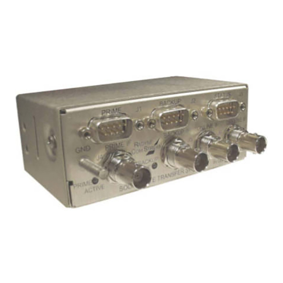
Chapter 1. INTRODUCTION Overview The STS11 (70/140 MHz) and STS11L (L-Band) Solid-State Transfer Switches (Figures 1-1 and 1-2) provide simple backup redundancy protection for the DM240-PIIC Modulators. Their straightforward design and easy access to connectors and LEDs allow for ease of use. Figure 1-1. - Page 12 STS11/STS11L Solid-State Transfer Switch Revision 0 Introduction MN-STS11-11 This page is intentionally blank. 1–2...
-
Page 13: Chapter 2. Installation
Chapter 2. INSTALLATION This section provides unpacking and installation instructions, and a description of external connections and backward alarm information. Installation Requirements The STS11 and STS11L Solid-State Transfer Switches are designed for installation in any convenient location (with the included brackets). They stand one rack unit (1RU) high (1.75 inches/4.45 cm) vertically, 4.4 inches (11.18 cm) wide, and 3.4 inches (8.63 cm) deep. -
Page 14: Unpacking
STS11/STS11L Solid-State Transfer Switch Revision 0 Installation MN-STS11-11 Unpacking The STS11/STS11L Solid-State Transfer Switch was carefully packaged to avoid damage and should arrive complete with the following items for proper installation: • STS11 or STS11L Solid-State Transfer Switch Unit • STS11 or STS11L Test Data Sheet •... - Page 15 STS11/STS11L Solid-State Transfer Switch Revision 0 Installation MN-STS11-11 DM240 Prime DM240 Backup Figure 2-1. STS11 Solid-State Transfer Switch to DM240 Connections 2–3...
- Page 16 STS11/STS11L Solid-State Transfer Switch Revision 0 Installation MN-STS11-11 Figure 2-2. STS11L Solid-State Transfer Switch to DM240 Connections Table 2-1. Interconnection Cable Part Numbers Cable Quantity Name Part Number Control Cable (DB-9 Straight Cable) CA/3677-1 IF Cable (75-Ohm BNC) CA/3598-36 L-Band Cable (50-Ohm SMA) CA/LMR200SMA3FT 2–4...
-
Page 17: Chapter 3. Operation
Chapter 3. OPERATION Solid-State Transfer Switch Operation A block diagram of the signal flow is shown in Figure 3-1 (70/140 MHz) and Figure 3-2 (L-Band) below. DM240 DM240 (Backup) (Prime) Figure 3-1. STS11 Functional Block Diagram... -
Page 18: Operating Procedures
STS11/STS11L Solid-State Transfer Switch Revision 0 Operation MN-STS11-11 DM240 DM240 (Prime) (Backup) Figure 3-2. STS11L Functional Block Diagram Operating Procedures The Solid-State Transfer Switch is designed to require minimal operator intervention and control during normal operation. After initial setup, the unit should operate in a relatively ‘transparent’... - Page 19 STS11/STS11L Solid-State Transfer Switch Revision 0 Operation MN-STS11-11 is non-revertive. That is, once a switch occurs, it requires a manual command (either through the M&C or from the front panel) to return the prime unit on-line. This will be the default operation, but the switching software is capable of implementing revertive switching as well.
- Page 20 STS11/STS11L Solid-State Transfer Switch Revision 0 Operation MN-STS11-11 Table 3-3. Switch Control Pinout Pin No. Signal Name Direction Description Signal Ground Input Modulator GND Backup Select Output One modulator is designated as Backup. This line is tied low on the Backup Mod Control connector. Input +12V DC Power nPrime_Sel...
-
Page 21: Chapter 4. Maintenance And Troubleshooting
Chapter 4. MAINTENANCE AND TROUBLESHOOTING Basic Troubleshooting and Maintenance This section provides information on the basic troubleshooting and repair procedures for the Solid-State Transfer Switch that may be performed on-site by qualified personnel. Only minor repairs will be discussed. For serious failures, the user should not attempt to repair the unit without first contacting Customer Service for further information and instructions. - Page 22 STS11/STS11L Solid-State Transfer Switch Revision 0 Maintenance and Troubleshooting MN-STS11-11 This page is intentionally blank.
-
Page 23: Chapter 5. Technical Specifications
Chapter 5. TECHNICAL SPECIFICATIONS Introduction This section defines the technical performance parameters and specifications for the Solid-State Transfer Switch. General Specifications Configuration: Modulator Only Switch Time: 50 msec Maximum Ports: IF: BNC, 75 Ohms L-Band: SMA, 50 Ohms Control Ports: DB-9 Male Status Port: DB-9 Male... - Page 24 STS11/STS11L Solid-State Transfer Switch Revision 0 Technical Specifications MN-STS11-11 This page is intentionally blank.
- Page 25 METRIC CONVERSIONS Units of Length Unit Centimeter Inch Foot Yard Mile Meter Kilometer Millimeter 1 centimeter — 0.3937 0.03281 0.01094 6.214 x 10 0.01 — — 1 inch 2.540 — 0.08333 0.2778 1.578 x 10 0.254 — 25.4 1 foot 30.480 12.0 —...
- Page 26 2114 85281 WEST TH STREET TEMPE ARIZONA 480 • 333 • 2200 PHONE 480 • 333 • 2161...