
Related Manuals for Comtech EF Data LCS-4


Summary of Contents for Comtech EF Data LCS-4
- Page 1 LCS-4 L-Band Combiner Switch Installation and Operation Manual Part Number MN/LCS4.IOM Revision 1...
- Page 3 Part Number MN/LCS4.IOM 9001 Registered Company. Revision 1 February 2, 2006 Copyright © Comtech EF Data, 2006. All rights reserved. Printed in the USA. Comtech EF Data, 2114 West 7th Street, Tempe, Arizona 85281 USA, (480) 333-2200, FAX: (480) 333-2161.
-
Page 4: Customer Support
Or, E-Mail can be sent to the Customer Support Department at: service@comtechefdata.com Contact us via the web at www.comtechefdata.com. To return a Comtech EF Data product (in-warranty and out-of-warranty) for repair or replacement: 1. Request a Return Material Authorization (RMA) number from the Comtech EF Data Customer Support Department. -
Page 5: Table Of Contents
INTRODUCTION .....................1–1 1.1 Introduction............................1–1 1.2 Functional Description ........................1–2 1.3 Features.............................. 1–4 1.4 Optional Items........................... 1–4 External BUC/LNB Fault Input ....................1–5 CHAPTER 2. INSTALLATION ....................2–1 2.1 Unpacking............................2–1 Unpack the LCS-4 as follows: ........................2–1 2.2 Mounting............................2–2... - Page 6 LCS-4 L-Band Combiner Switch Revision 1 Preface MN/LCS4.IOM CHAPTER 3. SYSTEM OPERATION..................3–1 3.1 Coaxial Connectors ........................... 3–1 3.2 Multi-Pin Connector Pinout......................3–2 3.3 Remote Port Connector ........................3–2 3.4 Fault and Online Status Connector....................3–3 3.5 (Future Option) Modulator Faults and TX On/Off Connector ............ 3–4 CHAPTER 4.
- Page 7 LCS-4 L-Band Combiner Switch Revision 1 Preface MN/LCS4.IOM Single-Thread BUC Installation....................... 5–9 5.5.1 Tools Required..........................5–9 5.5.2 Mounting Kits ..........................5–9 5.6 Installation ............................5–11 CHAPTER 6. CABLE INSTALLATION .................6–1 6.1 Introduction............................6–1 6.2 Single Configuration Cable Installation ..................6–2 6.3 Redundant Configuration Cable Installation.................
- Page 8 Revision 1 Preface MN/LCS4.IOM Figures Figure 1-1. LCS-4 L-Band Combiner Switch..................1–2 Figure 1-2. L-Band Multi-Modem Module Block Diagram (Redundancy) .........1–3 Figure 2-1. Typical Installation of the Optional Mounting Bracket, KT/6228-1 .........2–3 Figure 3-1. Rear Panel........................3–1 Figure 4-1. C-Band Redundant LNB (KT/9526-1)................4–3 Figure 4-2.
-
Page 9: About This Manual
About this Manual This manual provides installation and operation information for the Comtech EF Data LCS-4 L-Band Combiner Switch. This is a technical document intended for earth station engineers, technicians, and operators responsible for the operation and maintenance of the LCS-4. - Page 10 2.9 amps. USES The LCS-4 is fitted with two fuses, one each for line and neutral connections. These are contained within the body of the IEC power connector, behind a small plastic flap. For 115 and 130 volt AC operation, use T3, 15A, TO.75A, 20mm fuses.
- Page 11 The installation and connection to the line supply must be made in compliance to local or national wiring codes and regulations. The LCS-4 is designed for connection to a power system that has separate ground, line and neutral conductors. The equipment is not designed for connection to power system that has no direct connection to ground.
- Page 12 Preface MN/LCS4.IOM EMC (Electromagnetic Compatibility) In accordance with European Directive 89/336/EEC, the LCS-4 has been shown, by independent testing, to comply with the following standards: Emissions: EN 55022 Class B - Limits and methods of measurement of radio interference characteristics of Information Technology Equipment.
-
Page 13: Warranty Policy
24 months from the date of shipment. During the warranty period, Comtech EF Data will, at its option, repair or replace products that prove to be defective. For equipment under warranty, the customer is responsible for freight to Comtech EF Data and all related custom, taxes, tariffs, insurance, etc. - Page 14 LCS-4 L-Band Combiner Switch Revision 1 Preface MN/LCS4.IOM This page is intentionally left blank.
-
Page 15: Chapter 1. Introduction
If other user equipment is utilized, the customer shall obtain the documentation required to operate with the LCS-4 L-Band Combiner Switch. IMPORTANT The LCS-4 L-Band Combiner Switch has a 4-way transmit (TX) and Receive (RX) path combiner/splitter. • Combines four TX L-Band signals from L-Band modulators for delivery to an Outdoor Unit (ODU) or Block Up Converter (BUC). -
Page 16: Functional Description
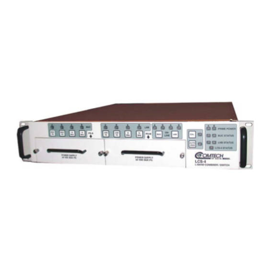
LCS-4 L-Band Combiner Switch Revision 1 Introduction MN/LCS4.IOM Figure 1-1. LCS-4 L-Band Combiner Switch 1.2 F UNCTIONAL ESCRIPTION On the TX-side, the TX signals of up to four modems are combined. The combined output is transmitted to one of the two outputs that feed an antenna system. Each TX output provides a 10 MHz BUC reference signal, a BUC power supply, and FSK communications. -
Page 17: Figure 1-2. L-Band Multi-Modem Module Block Diagram (Redundancy)
LCS-4 L-Band Combiner Switch Revision 1 Introduction MN/LCS4.IOM UPC Interface BUC PS A L-Band L-Band Σ DC, FSK, 10 MHz L-Band DC, FSK, 10 MHz Σ SPDT BUC A SPDT BUC A 10 MHz A Insertion Modulators Insertion & &... -
Page 18: Features
LCS-4 L-Band Combiner Switch Revision 1 Introduction MN/LCS4.IOM 1.3 F EATURES Standard FAST, or Hardware Phase Description Combiner, Splitter Hardware Single or dual AC PS for unit or BUC (options) Standard L-Band Splitting/Combining Standard Flash of all programmable items via Remote RS-232 port... -
Page 19: External Buc/Lnb Fault Input
LNB that have fault contacts for fault indication. Normally, this connector is used in applications where the ODU/BUC power supply or LNB power supply is external to the LCS-4 to permit a means of indicating a fault to the LCS-4 so that ODU/BUC or LNB switchover still occurs. - Page 20 LCS-4 L-Band Combiner Switch Revision 1 Introduction MN/LCS4.IOM This page intentionally left blank. 1–6...
-
Page 21: Chapter 2. Installation
Inspect shipping containers for damage. If shipping containers are damaged, keep them until the contents of the shipment have been carefully inspected and checked for normal operation. The LCS-4 and manual are packaged in pre-formed, reusable, cardboard cartons containing foam spacing for maximum shipping protection. -
Page 22: Mounting
2.2 M OUNTING If the LCS-4 is to be mounted in a rack, ensure that there is adequate clearance for ventilation, particularly at the sides. In rack systems where there is high heat dissipation, forced air-cooling must be provided by top and bottom mounted fans or blowers. -
Page 23: Figure 2-1. Typical Installation Of The Optional Mounting Bracket, Kt/6228-1
LCS-4 L-Band Combiner Switch Revision 1 Installation MN/LCS4.IOM Figure 2-1. Typical Installation of the Optional Mounting Bracket, KT/6228-1 2–3... - Page 24 LCS-4 L-Band Combiner Switch Revision 1 Installation MN/LCS4.IOM This page is intentionally left blank. 2–4...
-
Page 25: Chapter 3. System Operation
Chapter 3. SYSTEM OPERATION Figure 3-1. Rear Panel 3.1 C OAXIAL ONNECTORS Table 3-1. Coaxial Connectors Coaxial Connector Type Description Connector Type N, Female BUC B L-Band Output Type N, Female BUC A L-Band Output Type N, Female Modulator 1 L-Band Input, FSK I/O Type N, Female Modulator 2 L-Band Input Type N, Female... -
Page 26: Remote Port Connector
LCS-4 L-Band Combiner Switch Revision 1 Connector and Pinouts MN/LCS4.IOM 3.2 M ULTI ONNECTOR INOUT Table 3-2. Multi-Pin Connector Pinout Ref Des Description RS-232/485 Remote Port Online and Fault Status: Status: Form C contacts ODC/BUC A/B Online and LNB A/B Online BUC Faults: Form C contacts BUC A and B fault status LNB Faults: Form C contacts LNB A and B faults status. - Page 27 LCS-4 L-Band Combiner Switch Revision 1 Connector and Pinouts MN/LCS4.IOM 3.4 F AULT AND NLINE TATUS ONNECTOR J19, 25-pin D Female, Fault and Online Status. Pins Connected Pins Signal Name Signal Type Fault OK (No Power Direction Alarm Fault) BUC1_FLT_NO...
- Page 28 LCS-4 L-Band Combiner Switch Revision 1 Connector and Pinouts MN/LCS4.IOM 3.5 (F TX O UTURE PTION ODULATOR AULTS AND ONNECTOR Use of this connector is optional. It permits control of two 1:1 modulators by sensing the fault status from the 1:1 modem pair.
-
Page 29: General
Chapter 4. LOW NOISE BLOCK ASSEMBLY 4.1 G ENERAL The Low Noise Block (LNB) amplifies the input RF signal and down converts it to L-Band in the range of 950 to 1750 MHz (there may be instances that the L-Band range = 950 to 1450 MHz). -
Page 30: Chapter 4. Low Noise Block Assembly
LCS-4 L-Band Combiner Switch Revision 1 Low Noise Block Assembly MN/LCS4.IOM 4.2 O PTIONS Hardware IFL Cables Hardware Externally Referenced from IDU or Internally Referenced Hardware TX Reject Filter Mounting Kits Hardware 4.3 R LNB I EDUNDANT NSTALLATION The KT/9526-1 Mounting LNB Switch Kit, is the kit for the Redundant Systems. It can be mounted using one of the following kits: •... -
Page 31: Assemble Redundant C-Band Lnb
LCS-4 L-Band Combiner Switch Revision 1 Low Noise Block Assembly MN/LCS4.IOM 4.3.3 A SSEMBLE EDUNDANT Part No. Nomenclature 28P1084 Adapter CN/CX50NMALE Termination, 50Ω GA/GSKTCPOR229FULL Gasket, CPR229 HW/1/4-20X5/8BT Bolt, 1/4-20 HW/1/4-FLT Washer, Flat HW/1/4-SPLIT Washer, Split SW/WGS+48V-229 Switch, Waveguide WR229, +48 VDC *Customer-Furnished Note: Not included in Kit. -
Page 32: Figure 4-2. Switch Port Locations
LCS-4 L-Band Combiner Switch Revision 1 Low Noise Block Assembly MN/LCS4.IOM 1. Remove all protective tape from switch and keep it clean. 2. Position LNBs and gaskets (GA/GSKTCP229FULL) on Port 2 and Port 4 of switch. 3. Secure each LNB with eight bolts, flat washers, and split washers. -
Page 33: Figure 4-3. C-Band Lnb Switch
LCS-4 L-Band Combiner Switch Revision 1 Low Noise Block Assembly MN/LCS4.IOM 6. Position the customer-furnished TRF filter and a gasket on Port 4 of the switch. 7. Install the optional support bracket (FP/BR0085). Secure with eight bolts, flat washers, and split washers. -
Page 34: C-Band Lnb Installation
LCS-4 L-Band Combiner Switch Revision 1 Low Noise Block Assembly MN/LCS4.IOM 4.3.4 C-B LNB I NSTALLATION 1. Remove the protective cover from the antenna OMT and LNB. 2. Install the appropriate gasket on the antenna end of the LNB, as follows: a. - Page 35 LCS-4 L-Band Combiner Switch Revision 1 Low Noise Block Assembly MN/LCS4.IOM 4.4 K LNB I NSTALLATION The PL/10176-1, Mounting LNB Switch Kit, is the kit for the Redundant System. It can be mounted using one of the following kits: •...
-
Page 36: Figure 4-4. Ku-Band Redundant Lnb (Kt/10176-1)
LCS-4 L-Band Combiner Switch Revision 1 Low Noise Block Assembly MN/LCS4.IOM 4.4.3 A SSEMBLE EDUNDANT Part No. Nomenclature 99D1483 Waveguide Assy, WR75 CN/CX50NMALE Termination, CN-50Ω GA/GSKTWR75HALF Gasket, WR75 Half-Thickness HW/6-32X1/2SHSC Screw, Socket Cap HW/6-FLT Washer, Flat HW/6-SPLIT Washer, Split KT/2819... -
Page 37: Figure 4-5 Switch Port Locations
LCS-4 L-Band Combiner Switch Revision 1 Low Noise Block Assembly MN/LCS4.IOM 1. Remove all protective tape from switch and keep it clean. Connector 2. Position LNBs and gaskets (GA/GSKTCP75HALF) on Port 2 and Port 4 of switch. Port 3 3. Secure each LNB with eight bolts, Port 4 flat washers, and split washers. -
Page 38: Ku-Band Lnb Installation
LCS-4 L-Band Combiner Switch Revision 1 Low Noise Block Assembly MN/LCS4.IOM 4.4.4 K LNB I NSTALLATION The Ku-Band LNB is mounted to the OMT, as follows: 1. Remove the protective cover from the antenna OMT and LNB. 2. Install the appropriate gasket on the antenna end of the LNB, as follows: a. -
Page 39: Settings (Lnb) Lo, Mix And Spectrum
LCS-4 L-Band Combiner Switch Revision 1 Low Noise Block Assembly MN/LCS4.IOM 4.5 S (LNB) L ETTINGS IX AND PECTRUM 4.5.1 C-B Table 4-1. For C-Band: LO and MIX Information for Demodulator and LNB L-Band L-Band Demod (Offset) Frequency Frequency Spectrum... - Page 40 LCS-4 L-Band Combiner Switch Revision 1 Low Noise Block Assembly MN/LCS4.IOM This page is intentionally left blank. 4–12...
- Page 41 Chapter 5. BLOCK UP CONVERTER 5.1 G ENERAL The Block Up Converter (BUC) translates the L-Band carrier output from the IDU (in the 950 to 1750 MHz range) to C- or Ku-Band frequencies typically between: • C-Band: 5.845 and 6.425 GHz and amplifies the carrier to the desired TX power level. •...
-
Page 42: Chapter 5. Block Up Converter
LCS-4 L-Band Combiner Switch Revision 1 Block Up Converter MN/LCS4.IOM 5.2.1 A , AS/9528-1 SSEMBLE AVEGUIDE WITCH Part No. Nomenclature FP/WG0034 Termination, Small Fins FP/WG0043 Waveguide, CPRG137 FP/WG0051 Waveguide, CPRG137 GA/GSKTCP137FULL Gasket, CP137 Full HW/10-32X5/8SHC Screw, Socket Head Cap HW/10-FLT... - Page 43 LCS-4 L-Band Combiner Switch Revision 1 Block Up Converter MN/LCS4.IOM 5.2.2 A BUC M (KT/9826-1) SSEMBLE OUNTING Part No. Nomenclature FP/BR10351-1 Bracket, Mounting FP/BR10352-1 Bracket, Mounting FP/WG0034 Termination, Small Fins FP/WG10359-1 Waveguide 3.75X2 GA/GSKTCP137FULL Gasket, Full Thickness, CP137 GA/GSKTCP137HALF Gasket, Half Thickness, CP137...
-
Page 44: Ku-Band Redundant Buc Assembly Procedures
LCS-4 L-Band Combiner Switch Revision 1 Block Up Converter MN/LCS4.IOM 5.3 K BUC A EDUNDANT SSEMBLY ROCEDURES Part No. Nomenclature PL/9527-1 BUC Assembly, Ku-Band KT/9828-1 Mounting Kit, Ku-Band 5.3.1 A , PL/9527-1 SSEMBLE AVEGUIDE WITCH Part No. Nomenclature FP/7943-1 Bracket, Support Redundant Switch... -
Page 45: Assemble Ku-Band Redundant Bucs
LCS-4 L-Band Combiner Switch Revision 1 Block Up Converter MN/LCS4.IOM 5.3.2 A SSEMBLE EDUNDANT Refer to BUC manufacturer’s documentation for installation on the Comtech EF Data assembly. IMPORTANT Optional: Assemble brackets (FP/BR10352-1) on Bracket (FP/BR10351-1) and secure with two bolts, four flat washers, four split washers, and two hex nuts. - Page 46 LCS-4 L-Band Combiner Switch Revision 1 Block Up Converter MN/LCS4.IOM This page is intentionally left blank. 5–6...
-
Page 47: Lo, Mix And Spectrum Settings
LCS-4 L-Band Combiner Switch Revision 1 Block Up Converter MN/LCS4.IOM 5.4 LO, MIX PECTRUM ETTINGS 5.4.1 C-B Table 5-1. LO, MIX, and MOD Spectrum Settings for Modulator and BUC Modem RF Start RF End (Offset) Spectrum CEFD Frequency Frequency Freq. -
Page 48: Ku-Band
LCS-4 L-Band Combiner Switch Revision 1 Block Up Converter MN/LCS4.IOM 5.4.2 K Table 5-2. LO, MIX, and MOD Spectrum Settings for Modulator and BUC Modem RF Start RF End (Offset) Spectrum CEFD Frequency Frequency Freq. (Utility Supply SPAR Feed Mount Kit... -
Page 49: Table 5-3. Optional: C-Band Mounting Kit, Kt/5738-1 (Buc To Omt)
LCS-4 L-Band Combiner Switch Revision 1 Block Up Converter MN/LCS4.IOM 5.5 S BUC I INGLE HREAD NSTALLATION After removing the protective covers, ensure that no foreign material (FOD) or moisture enters. CAUTION 5.5.1 T OOLS EQUIRED 1/2-inch Box Wrench (or equivalent) -
Page 50: Figure 5-1. Mounting Kit, Kt/9928-1
LCS-4 L-Band Combiner Switch Revision 1 Block Up Converter MN/LCS4.IOM Item Part No. Nomenclature **Remarks FP/9026-1 Bracket, QP FP/BR9927-1 Bracket, Upper Use with Option B BUC HW/M4FLAT Washer, Flat Use with Option B BUC HW/M4LOCK Washer, Lock Use with Option B BUC... -
Page 51: Installation
LCS-4 L-Band Combiner Switch Revision 1 Block Up Converter MN/LCS4.IOM 5.6 I NSTALLATION To install the BUC to the antenna: 1. If installed: Remove protective covers from the antenna OMT and SSPA. After removing the protective cover, ensure that no foreign material (FOD) or moisture enters the antenna waveguide or BUC. - Page 52 LCS-4 L-Band Combiner Switch Revision 1 Block Up Converter MN/LCS4.IOM B BUC PTION Step Procedure Install bracket (2, figure 5-9) to the BUC. Secure with two screws (5), two lock washers (4), and two flat washers (3). Position universal lower ‘L’ bracket (1) to feed horn, loosely fasten with bolt (21), flat washer (20), lock washer (22), and nut (23).
-
Page 53: Chapter 6. Cable Installation
Chapter 6. CABLE INSTALLATION 6.1 I NTRODUCTION Take care during cable installation. Install the cables using the most direct route and secure with clamps and ties. Avoid all sharp bends. Cable connectors used in outdoor applications shall be sealed to avoid leakage, particularly, N-Type connectors. -
Page 54: Single Configuration Cable Installation
NSTALLATION The LCS-4 Single Configuration consists of the LCS-4, up to four modems, one LNB and one BUC. The LCS-4 shall be positioned above Modems A, B, C, and D. Refer to Figure 6-1. Figure 6-1. Single Configuration Cable Installation... -
Page 55: Redundant Configuration Cable Installation
NSTALLATION The LCS-4 Redundant Configuration consists of the LCS-4, up to four modems, two LNBs and two BUCs. The LCS-4 shall be positioned above Modems A, B, C, and D. Refer to Figure 6-2. Figure 6-2. Redundant Configuration Cable Installation... - Page 56 LCS-4 L-Band Combiner Switch Revision 1 Cable Installation MN/LCS4.IOM This page is intentionally left blank 6–4...
-
Page 57: Chapter 7. Front Panel Control
The purpose of the front panel is to control the state of the power supplies, the references, the online condition (in redundancy mode), and whether the redundancy mode is in Auto or Manual mode. It is also a visual indication of the fault status of the LCS-4 and the devices that are being monitored. -
Page 58: Buc Control
LCS-4 L-Band Combiner Switch Revision 1 Front Panel Control MN/LCS4.IOM 7.2.1 BUC C ONTROL The following controls the BUC power supplies and BUC 10 MHz reference. Controls Description BUC A Power Supply The BUC A power supply switch toggles the power supply from BUC A ON and OFF. -
Page 59: Lnb Control
LCS-4 L-Band Combiner Switch Revision 1 Front Panel Control MN/LCS4.IOM 7.2.2 LNB C ONTROL The following controls the LNB power supplies and LNB 10 MHz reference. Controls Description LNB A Power Supply The LNB A power supply switch toggles the power supply from LNB A ON and OFF. -
Page 60: Current Calibration
The Redundancy Mode switch enables/disables AUTO mode, this is indicated by the associated LED (refer to Table 7-1 for various LED conditions). When AUTO mode is enabled, the LCS-4 will automatically switch between BUC and LNB in Redundancy Mode when a fault occurs. The keypad and Remote Port are also ‘locked’... -
Page 61: Led Conditions
LCS-4 L-Band Combiner Switch Revision 1 Front Panel Control MN/LCS4.IOM 7.2.5 LED C ONDITIONS Following is allowed conditions of the LEDs on the front panel. CONDITION GREEN FLASHING DESCRIPTION Prime Power A Disabled Prime Power A Status Prime Power B... - Page 62 LCS-4 L-Band Combiner Switch Revision 1 Front Panel Control MN/LCS4.IOM 7.3 O PERATION 7.3.1 AUTO / MAN O PERATION The AUTO/Man switch selects automatic redundancy operation of the unhit in the AUTO mode and permits operation of the unit from the front panel when MAN is selected.
-
Page 63: Table 7-1. Fault Definitions For Switchover For Lnb Or Odu/Buc
OLTAGE URRENT Contact Comtech EF Data Customer Support for a procedure for setting the CAL current for the LNB in the event it uses an internal ovenized oscillator. These units draw a higher current at turn ON of the LNB voltage in order to heat up the crystal. After warm-up, the current drops back to the normal steady-state value. - Page 64 LCS-4 L-Band Combiner Switch Revision 1 Front Panel Control MN/LCS4.IOM This page is intentionally left blank. 7–8...
-
Page 65: Operation
Appendix A. REMOTE CONTROL OPERATION DESCRIPTION The electrical interface is either an RS-485 multi-drop bus (for the control of many devices) or an RS-232 connection (for the control of a single device), and data is transmitted in asynchronous serial form, using ASCII characters. Control and status information is transmitted in packets, of variable length, in accordance with the structure and protocol defined in later sections. -
Page 66: Eia-232
LCS-4 L-Band Combiner Switch Revision 1 Remote Control Operation MN/LCS4.IOM RS-485 (Full-duplex) summary: • Two differential pairs – one pair for controller to target, one pair for target to controller. • Controller-to-target pair has one line driver (controller), and all targets have line–receivers. - Page 67 LCS-4 L-Band Combiner Switch Revision 1 Remote Control Operation MN/LCS4.IOM A.2.1 P ACKET TRUCTURE ONTROLLER ARGET Target Address Instruction Code Optional Start of Packet Address De-limiter Code Qualifier Arguments End of Packet < = or ? Carriage ASCII code 60...
- Page 68 LCS-4 L-Band Combiner Switch Revision 1 Remote Control Operation MN/LCS4.IOM A.2.1.2 A DDRESS Up to 9999 devices can be uniquely addressed. In RS-232 and RS-485 applications, the permissible range of values is 1 to 9999. It is programmed into a slave unit using the Set Physical Address (SPA) command.
- Page 69 LCS-4 L-Band Combiner Switch Revision 1 Remote Control Operation MN/LCS4.IOM From Target to Controller, the only permitted values are: = (ASCII code 61) ? (ASCII code 63) ! (ASCII code 33) * (ASCII code 42) # (ASCII code 35) They have these meanings: The = code (target to controller) is used in two ways: •...
-
Page 70: Commands Or Responses
LCS-4 L-Band Combiner Switch Revision 1 Remote Control Operation MN/LCS4.IOM A.2.1.5 M ESSAGE RGUMENTS Arguments are not required for all messages. All arguments are ASCII codes for the characters 0 to 9 (ASCII 48 to ASCII 57), period (ASCII 46) and comma (ASCII 44). - Page 71 LCS-4 L-Band Combiner Switch Revision 1 Remote Control Operation MN/LCS4.IOM Command Arguments Response to Query (Instruction for Cmd or Description of Arguments Command (Instruction Parameter Code and Response Note that all arguments are ASCII (Target to code and Response to query...
- Page 72 LCS-4 L-Band Combiner Switch Revision 1 Remote Control Operation MN/LCS4.IOM Command Arguments Response to Query (Instruction for Cmd or Description of Arguments Command (Instruction Parameter Code and Response Note that all arguments are ASCII (Target to code and Response to query...
- Page 73 LCS-4 L-Band Combiner Switch Revision 1 Remote Control Operation MN/LCS4.IOM Command Arguments Response to Query (Instruction for Cmd or Description of Arguments Command (Instruction Parameter Code and Response Note that all arguments are ASCII (Target to code and Response to query...
- Page 74 1 byte, Command or Query. STT=(message ok) STT? STT=x (same format as command value of 0,1 STT Selects whether the LCS-4 will act as a 1:1 STT? (Received ok, arguments) Function redundancy controller or a Combiner for the TX but invalid...
- Page 75 1 byte, Command or Query. SRT=(message ok) SRT? SRT=x (same format as command value of 0,1 SRT Selects whether the LCS-4 will act as a 1:1 SRT? (received ok, arguments) Function redundancy controller or a Combiner for the RX but invalid...
- Page 76 Example: RSN=000000165 999999999 Retrieve 12 bytes Query only. RET? RET=xxxxxxxxxxxx Equipment alpha LCS-4 returns a string indicating the Model Number (same format as command Type numerical and the value of internal software revision installed. arguments) Example: RET=LCS-4 V1.0.3 Lamp Test LMP= 1 byte, Command only.
- Page 77 LCS-4 L-Band Combiner Switch Revision 1 Remote Control Operation MN/LCS4.IOM Command Arguments Response to Query (Instruction for Cmd or Description of Arguments Command (Instruction Parameter Code and Response Note that all arguments are ASCII (Target to code and Response to query...
- Page 78 Where: yyyyyyyyyy = being the fault description ZZ = being the alarm type FT=Fault OK=Clear IF=Information If there are no new events, the LCS-4 will reply with LNE* Retrieve 2 bytes, Query Only. TNE? TNE=xx Number of...
- Page 79 (Target to Controller) Summary 1 byte, Query only. SFS? SFS=x Fault Status value of 0,1 Used to Query the status of the LCS-4 Summary Fault (same format as command Relay. arguments) Where: 0=OK 1=FT Example: SFS=0 Terminal 1 byte, Query only.
- Page 80 48 and 57. Controller) qualifier) (Target to Controller) Retrieve 159 bytes, Query only. RMS? RMS=x…x Maintenance alpha Used to Query the maintenance status of the LCS-4 (same format as command Status numerical Example: RMS=’cr’ arguments) 48VPS=048.0’cr’ 12VP1=012.0’cr’ 12VP2=012.0’cr’ P5.0V=+05.0’cr’ N5.0V=-05.0’cr’...
- Page 81 (Target to Controller) Concise 32 bytes, Query only. CUS? CUS=x….x (see description for Utility Status alpha Used to Query the Utility status of the LCS-4 response details of arguments) numerical in comma delimited. Example: CUS=aaaaa,bbbbb,ccc.c,ddd.d,eee,f,g,h,’cr’’lf’] where: aaaaa = BUC A CAL Current bbbbb = BUC B CAL Current ccc.c = LNB A CAL Current...
- Page 82 Query only. CAS? CAS=abcdefghijklmnopqr (see Alarm Status numerical Used to Query the Alarm status of the LCS-4 response description for details of is comma delimited. arguments) Example: CMS=abcdefghijklmnopqr’cr’’lf’ where: a thru t = 0 or 1, 0 = OK 1 = FT...
- Page 83 LCS-4 L-Band Combiner Switch Revision 1 Remote Control Operation MN/LCS4.IOM Command Arguments Response to Query (Instruction for Cmd or Description of Arguments Command (Instruction Parameter Code and Response Note that all arguments are ASCII (Target to code and Response to query...
- Page 84 LCS-4 L-Band Combiner Switch Revision 1 Remote Control Operation MN/LCS4.IOM OTES A-20...
-
Page 85: Appendix B. Specifications
0 to –40 dBm, operating per port, +10 dBm maximum per port TX Uplink Power Control (UPC) Access Input and output SMA female connectors. Routes composite modulator signals through UPC equipment then back to LCS-4 for external power leveling. TX UPC Signal Level Combined TX input level –7 dB typical both connections... - Page 86 LCS-4 L-Band Combiner Switch Revision 1 Specifications MN/LCS4.IOM Table B-1. General Specification (Continued) 10 MHz Reference: To BUC Via TX (BUC)/RX (LNB) center conductor, selectable ON/OFF 0 ± 3 dBm To LNB -3 ± +3 dBm Spurious Emissions TX Toward BUC or -55 dBc over 55 MHz to 2.2 GHz measured in a 4 kHz BW with...
-
Page 87: Environmental And Physical Specifications
LCS-4 L-Band Combiner Switch Revision 1 Specifications MN/LCS4.IOM B.2 E NVIRONMENTAL AND HYSICAL PECIFICATIONS Table B-2. Environmental and Physical Specifications Environmental Specifications Temperature 0 to -50°C (32 to 122°F) Humidity 95% Non-condensing Operation Shock MILS-STD-167-1 When any one corner of the unit is dropped from 1 cm onto a hard surface, the unit will not take any errors or faults. - Page 88 LCS-4 L-Band Combiner Switch Revision 1 Specifications MN/LCS4.IOM OTES...
-
Page 89: Metric Conversions
Metric Conversions Units of Length Unit Centimeter Inch Foot Yard Mile Meter Kilometer Millimeter 1 centimeter — 0.3937 0.03281 0.01094 0.01 — — 6.214 x 10 1 inch 2.540 — 0.08333 0.2778 0.254 — 25.4 1.578 x 10 1 foot 30.480 12.0 —... - Page 90 2114 85281 WEST TH STREET TEMPE ARIZONA 480 • 333 • 2200 PHONE 480 • 333 • 2161...